


ISO/IEC 9506-3:1991
(Main)Industrial automation systems — Manufacturing message specification — Part 3: Companion standard for robotics
Industrial automation systems — Manufacturing message specification — Part 3: Companion standard for robotics
Systèmes d'automatisation industrielle — Spécification de messagerie industrielle — Partie 3: Norme d'accompagnement pour la robotique
General Information
- Status
- Withdrawn
- Publication Date
- 07-Aug-1991
- Withdrawal Date
- 07-Aug-1991
- Current Stage
- 9599 - Withdrawal of International Standard
- Start Date
- 04-Nov-1999
- Completion Date
- 12-Feb-2026
Relations
- Effective Date
- 06-Jun-2022
- Effective Date
- 06-Jun-2022
- Effective Date
- 15-Apr-2008
- Effective Date
- 15-Apr-2008
ISO/IEC 9506-3:1991 - Industrial automation systems -- Manufacturing message specification
ISO/IEC 9506-3:1991 - Systemes d'automatisation industrielle -- Spécification de messagerie industrielle
Get Certified
Connect with accredited certification bodies for this standard

National Aerospace and Defense Contractors Accreditation Program (NADCAP)
Global cooperative program for special process quality in aerospace.
CARES (UK Certification Authority for Reinforcing Steels)
UK certification for reinforcing steels and construction.
DVS-ZERT GmbH
German welding certification society.
Sponsored listings
Frequently Asked Questions
ISO/IEC 9506-3:1991 is a standard published by the International Organization for Standardization (ISO). Its full title is "Industrial automation systems — Manufacturing message specification — Part 3: Companion standard for robotics". This standard covers: Industrial automation systems — Manufacturing message specification — Part 3: Companion standard for robotics
Industrial automation systems — Manufacturing message specification — Part 3: Companion standard for robotics
ISO/IEC 9506-3:1991 is classified under the following ICS (International Classification for Standards) categories: 25.040.30 - Industrial robots. Manipulators. The ICS classification helps identify the subject area and facilitates finding related standards.
ISO/IEC 9506-3:1991 has the following relationships with other standards: It is inter standard links to ISO/IEC 9506-3:1991/Amd 2:1997, ISO/IEC 9506-3:1991/Cor 1:1993; is excused to ISO/IEC 9506-3:1991/Amd 2:1997, ISO/IEC 9506-3:1991/Cor 1:1993. Understanding these relationships helps ensure you are using the most current and applicable version of the standard.
ISO/IEC 9506-3:1991 is available in PDF format for immediate download after purchase. The document can be added to your cart and obtained through the secure checkout process. Digital delivery ensures instant access to the complete standard document.
Standards Content (Sample)
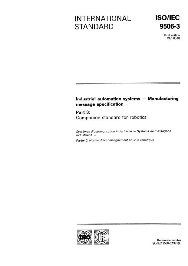
INTERNATIONAL
STANDARD
First edition
1991-08-01
Industrial automation systems - Manufacturing
message specification -
Part 3:
Companion standard for robotics
SysMmes d’automatisation industrielle - Systt2me de messagerie
industrielle -
Partie 3: Norme d’accompagnement pour /a robotique
---
--
- 3
i
”
=
= =
=
z
=
::
I 2
;
i
= =
‘;
=
GE Reference number
=.
c_
Z
z
GE
- -
lSO/lEC 9506-3:1991(E)
p-
ISOllEC 9506-3: 1991 (E)
Page
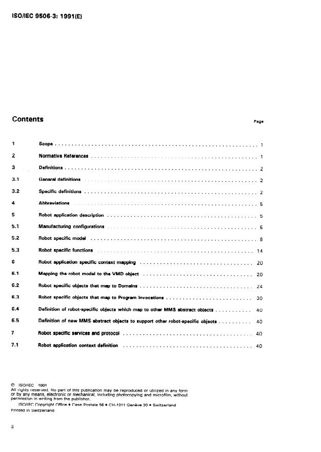
Contents
............................................................. 1
1 scope
2 Normative References
..................................................
..........................................................
3 Definitions
3.1 General definitions
....................................................
3.2 Specific definitions
....................................................
Abbreviations .
Robot application description 5
5 .
5.1 Manufacturing configurations
.............................................
5.2 Robot specific model
..................................................
5.3 Robot specific functions
..............................................
6 Robot application specific context mapping .
6.1 Mapping the robot model to the VMD object .
6.2 Robot specific objects that map to Domains .
6.3 Robot specific objects that- map to Program Invocations .
Definition of robot-specific objects which map to other MMS abstract objects . 40
6.4
Definition of new MMS abstract objects to support other robot-specific objects . 40
6.5
7 Robot specific services and protocol
.......................................
Robot application context definition
7.1 .
0 ISO/IEC 1991
All rights reserved. No part of this publication may be reproduced or utilized in any form
or by any means, electronic or mechanical, including photocopying and microfilm, without
permission in writing from the publisher.
ISO/lEC Copyright Office 0 Case Postale 56 l Cl-l-1231 Get-&e 20 l Switzerland
Printed in Switzerland
ii
ISO/IEC 9506-3: 1991 (E)
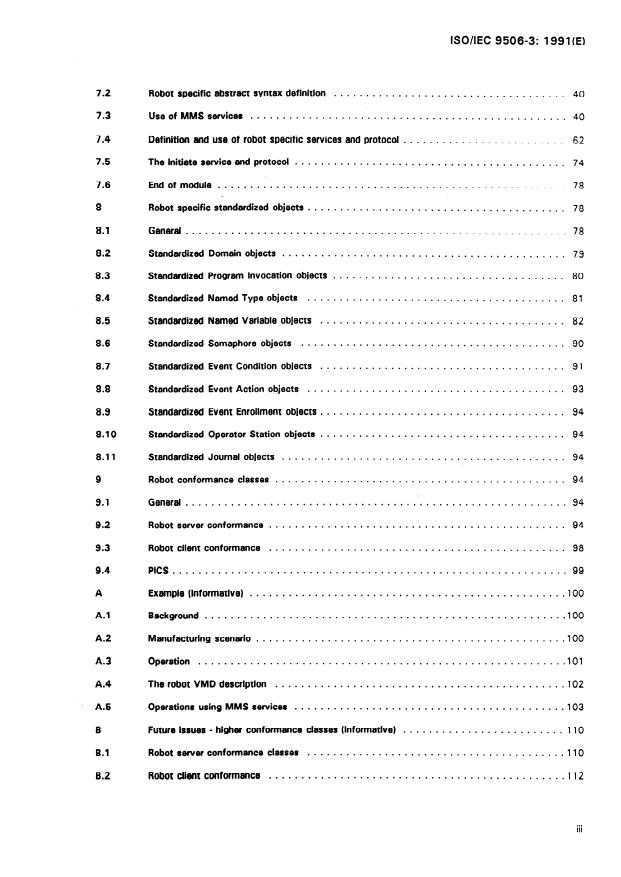
7.2 Robot specific abstract syntax definition . 40
US8 of MMS services 40
7.3 .
7.4 Definition and use of robot specific services and protocol . 62
TheinitiateswviceandprOtOCOl. . 74
7.5
Endofmodule . . . . . . . . . . . . . . . . . . . . . . . . . . . . . . . . . . . . . . . . . . . . . . . . . . . . . . 78
7.6
Robot specific standardized objects 78
8 .
Genetal . 78
8.1
8.2 Standardized Domain objects .
.................................... 80
8.3 Standardized Program Invocation objects
Standardized Named Type objects . 81
8.4
...................................... 82
8.5 Standardized Named Variable objects
8.6 Standardized Semaphore objects .
...................................... 9 1
8.7 Standardized Event Condition objects
........................................ 93
8.8 Standardized Event Action objects
Standardized Event Enrollment objects . 94
8.9
Standardized Operator Station objects .
8.10
............................................ 94
8.11 Standardized Journal objects
9 Robot conformance classes . . . . . . . . . . . . . . . . . . . . . . . . . . . . . . . . . . . . . . . . . . . . . 94
General. .
9.1
Robot server conformance .
9.2
Robot client conformance . ; .
9.3
9.4 PIGS .
................................................. 100
A Example (Informative)
A.1 Background. . .10 0
A.2 Manufacturing scenario .
..10 1
A.3 Operation .
.102
A.4 The robot VMD description .
. A.5 Operations using MMS services .
......................... 110
B Future issues - higher conformance classes (Informative)
........................................ 110
B.l Robot server conformance classes
Robot dent conformance . .112
B.2
. . .
III
ISO/IEC 9506-3: 1991 (E)
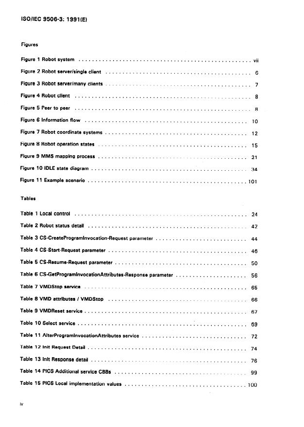
Figures
Figure 1 Robot system vii
...................................................
Figure 2 Robot server/single client 6
...........................................
Figure 3 Robot server/many clients
...........................................
Figure 4 Robot client
....................................................
Figure 5 Peer to peer 8
....................................................
Figure6lnformationflow 10
................................................
Figure 7 Robot coordinate systems 12
..........................................
Figure 8 Robot operation states 15
............................................
Figure 9 MMS mapping process 21
............................................
Figure 10 IDLE state diagram 34
...............................................
Figure 11 Example scenario 101
...............................................
Tables
Table 1 Local control 24
...................................................
Table 2 Robot status detail
...............................................
Table 3 CS-CreateProgramlnvocation-Request parameter .
Table 4 CS-Start-Request parameter
.........................................
Table 5 CS-Resume-Request parameter
.......................................
Table 6 CS-GetProgramlnvocationAttributes-Response parameter 56
.....................
Table 7 VMDStop service 65
................................................
Table 8 VMD attributes / VMDStop
.........................................
Table 9 VMDReset service
................................................
Table 10Selectservice I .
..................................
Table 11 AlterProgramlnvocationAttributes service 72
...............................
Table 12 lnit Request Detail 74
...............................................
Table 13 lnit Response detail . . . . . . . . . . . . . . . . . . . . . . . . . . . . . . . . . . . . . . . . . . . . . . 76
Table 14 PIGS Additional service CBBs 99
.......................................
Table 15 PJCS Local implementation values
....................................
iV
ISODEC 9506-3: 1991 (E)
Foreword
IS0 (the international Organization for Standardization) and IEC (the
international Eiectrotechnicai Commission) form the specialized system
for worldwide standardization. National bodies that are members of IS0
or IEC participate in the development of international Standards through
technical committees established by the respective organization to deal
with particular fields of technical activity. IS0 and IEC technical com-
mittees collaborate in fields of mutual interest. Other international or-
ganizations, governmental and non-governmental, in liaison with IS0
and IEC, also take part in the work.
in the field of information technology, IS0 and IEC have established a
joint technical committee, iSO/iEC JTC 3. Draft international Standards
adopted by the joint technical committee are circulated to national bod-
ies for voting. Publication as an international Standard requires ap-.
proval by at least 75 % of the national bodies casting a vote.
international Standard iSO/iEC 9506-3 was prepared by Joint Technical
Committee iSO/TC 184, industrial automation systems md integration.
iSO/iEC 9506 consists of the following parts, under the general title In-
dustrial automation systems - Manufacturing message specification:
-
Part I: Service definition
-
Part 2r Protocol specification
-
Part 3: Companion standard for robofics
Annexes A and B are for information only.
V
ISO/IEC 9506-3: 1991 (E)
This part of ISO/IEC 9506 is intended to be used in an open communication system employing robots and robotic
systems connected to a communication network conforming to the OS model (IS0 7498). This part of ISO/IEC
9506 also recognizes that the robot can act as a controller (client) to devices connected to it such as vision
systems and grippers. Client conformance for communication to such devices is not defined by this part of ISO/IEC
9506. Conformance requirements for communication to such devices are defined by the companion Standard
appropriate to that device or by ISO/IEC 9506-l and ISO/IEC 9506-Z.
This part of ISO/lEC 9506 does define conformance requirements for the robot when used in a network with
multiple clients. The messages are described using the method defined in IS0 8824.
This part of ISO/iEC 9506 provides a description of several conformance classes including a base class. This base
class is considered as the minimum conformance for robots connected as a “slave” or server to a host computer
or client device on the network. The base class forms the “kernel” of conformance for robots in these types of
networks. All other conformance classes will be additions to the base class. This part of ISO/IEC 9506 also
provides the robot specific services and protocol including the abstract syntax notation for protocol elements
which are undefined in the MMS-General-Module.
This part of ISO/IEC 9506 also recognizes that the robot can act as a controller to devices connected to it such
as vision systems and grippers. This part of ISO/IEC 9506 identifies the requirements for communications in such
a manner but does not identify MMS service and protocol conformance requirements for the robot when acting
in a client role. These requirements are identified by the companion, standard covering the device to which the
robot intends to communicate.
MMS is intended to be used with yet other standards designed to achieve a systematic and uniform approach to
Open Systems Interconnection of Information Processing Systems as defined in IS0 7498. As such, MMS is
positioned within the application layer of the GSt model. It defines the Application Service Element and the
protocol required to extend information systems networks to the programmable control devices of the automated
factory environment. The services defined by MMS are generic and intended to be referenced by the companion
standards, each of which is oriented towards a more specific class of application.
This part of ISO/IEC 9506 recognizes that safe operation of robots is required at all times. Safety requirements
for robots are specified in IS0 DIS 10218. All robot actions delineated in this part of ISOllEC 9506 are permissible
under the safety standard.
Implementation of this part of ISO/IEC 9506 requires a minimum implementation of MMS. This is covered in Clause
9 which references the conformance requirements of ISO/IEC 9506-l and 2. Implementers of MMS for robots and
robotic systems should have a thorough understanding of MMS for proper implementation of this part of ISO/IEC
9506. Implementers should also have a thorough understanding of the modeling, services and protocol defined
in this part of ISO/IEC 9506. Users of robots and robotic systems are directed to the clauses on modeling and
services found in this document.
For the purpose of this part of ISO/IEC 9506, the term “robot” means “manipulating industrial robot” as defined
in lSO/TR 8373. As used in this part of ISO/IEC 9506, a robot will generally refer to the manipulator together with
its control system and any ancillary equipment, devices, sensors, or communications links, necessary for the robot
to perform its task. Figure 1 illustrates the elements of the robot system as described in this part of ISO/IEC 9506.
Since the definitions of ISOflR 8373 only describe robot systems with a single arm and this part of ISO/IEC 9506
anticipates robots with multiple arms operating in a coordinated fashion, these definitions have been generalized.
The term “robot system controller” will refer to the (single) task program operating with the (possible multiple)
control program of the robot arm(s) of the system.
“MMS services” refers to the abstract services defined in ISO/IEC 9506-l and “MMS protocol” refers to 0~
protocol defined in ISO/IEC 9506-2.
Vi
ISO/IEC 9506-3: 1991 (El
Robot System
Robot Arm
Communication
Interface
Control *Program
/
Task
I .,%~~sm I
Program
Manipulator
I
1 End Effectgr 1
Auxiliary
Device
Power Supply
0 or more
1 of more
vii
This page intentionally left blank
INTERNATIONAL STANDARD ISO/IEC 9506-3:1991 (E)
Industrial automation systems - Manufacturing message
specification -
Part 3:
Companion standard for robotics
1 scope
This part of ISOAEC 9506:
describes the model of a robot and how the attributes of the robot are mapped onto the attributes of a
Virtual Manufacturing Device (VMD),
defines the robot specific services and protocol including the abstract syntax notation for protocol
elements requiring companion standard specification by MMS,
defines robot specific standardized objects,
cl
provides a description of conformance classes including a base class and several enhanced classes.
d)
Definitions are provided of the services and protocol of robots operating as a server in the abstract syntax defined
in this part of ISO/IEC 9506. The semantics of MMS services performed by robots while communicating under
other abstract syntaxes are not defined by this part of ISO/IEC 9506. This part of ISO/IEC 9506 does not identify
MMS service and protocol conformance requirements for a robot acting in a client role. These requirements are
intended to be identified by the companion standard covering the device to which the robot intends to
communicate.
2 Normative References
The following standards contain provisions which, through reference in this text, constitute provisions of this part
of ISO/IEC 9506. At the time of publication, the editions indicated were valid. All standards are subject to revision,
and parties to agreements based on this part of ISOAEC 9506 are encouraged to investigate the possibility of
applying the most recent editions of the standards listed below. Members of IS0 and IEC maintain registers of
currently valid international standards.
lndus trial automation s ys terns - Manufacturing Message Specification - Part I -
ISO/IEC 9506-l : 1990
Service definition
Industrial automation systems - Manufacturing Message Specification - Part 2 -
ISO/IEC 95062: 1990
Protocol specification
lnforma tion processing s ys terns - Open Systems Interconnection - Basic
IS0 7498: 1984
Reference Model
ISOllEC 9506-3: 1991 (E)
ISOKR 8509: 1985 Information processing systems - Open Systems Interconnection - Sewice
Conventions
IS0 8824: 1987 lnforma tion processing s ys terns - Open S ys terns ln terconnection - Specification
of A&tract Syntax Notation One (ASN. 1)
Information processing systems - Open Systems interconnection - File Transfer,
IS0 857 1: 1988
Access and Management
information processing systems - Open Systems Interconnection - Sewice
IS0 8649: 1988
definition for the Association Control Sewice Element
IS0 8650: 1988 lnforma tion processing s ys terns - Open Systems Interconnection - Protocol
specification for the Association Control Sewice Element
Manipulating Industrial Robots - Standard for Safety
IS0 DIS 10218’
Manipulating lndus trial Robots - Vocabulary
lSO/TR 8373: 1988
IS0 9787: 1990 Manipulating Industrial Robots - Coordinate S ys terns and Motions
’ To be published
3 Definitions
3.1 Generd definitions
Clause 3 of ISOAEC 9506-l :1990 and clause 3 of ISO/IEC 9506-2: 1990 list a number of terms defined in IS0
7498, in ISOflR 8509, and in IS0 8824, as well as its own definitions. lSO/TR 8373 and IS0 9787 also define
a number of terms used in this part of ISOAEC 9506. These definitions are included in this part of ISOIIEC 9506
by reference.
3.2 Specific defmiticms
I The inherent set of control instructions which defines the capabilities, actions, and responses of a robot system.
This type of program is fixed and usually not modifiable by the user.
ISO/IEC 9506-3: 1991 (E)
3.2.2 cydez
A single executidn of a task program.
3.2.3 local amtrd:
A boolean value which indicates whether or P not it is possible for rem0
te opera tions to ef f ect changes in the state
of the MMS server. If local control is true, remote operation s cannot
change the sta te of the server
This definition is appropriate to MMS Companion Standards and is different from that contained in IS0 DIS
Note:
10218.
3.2.4
An automaticall y controlled, reprogra mmable, multi-purpose, , manipulative machine with
several degrees of
freedom, which can be either fixed in place of mobile for use in Industrial au tomation
applic ‘ations.
ning clauses of this part of ISO/IEC 9506, the term “robot” will mean
Nota: For the purposes of the remai
“manipulating industrial robot”.
3.2.5 fnmipbta:
A machine, the mechanism or which usually consists of a senes of segments jointed or sliding relative to one
another, for the purpose of grasping and/or moving objects tpleces 01 tools) usually in several degrees of freedom.
It may be controlled by an operator, a programmable electronrc controller, or any logic system (for example cam
device, wired, etc.).
3.2.6 math ended:
A boolean value which if TRUE indicates that a valid command presented to the control program of a robot arm
will result in motion of the arm.
3.2.7 poaa
Combination of position and orientation of a part of a robot (for example its mechanical interface) or of a
workpiece in a coordinate system.
ISOllEC 9506-3: 1991 (E)
3.2.8 remoter:
An operation involving data acquisition or control operating over an OSI communication network using MMS
services.
3.2.9 dxDt mm:
As used in this part of ISO/IEC 9506, a manipulator, an end effector, its power supply, and the control ram
prog
which controls the manipulator.
3.2.10 robot system:
A robot system includes:
- the robot (hardware and software) consisting of the manipulator whether mobile or not; power supply and
control system;
- the end-effector(
- any equipment, devices, or sensors required for the robot to perform its task;
- any communication interface that is operating and monitoring the robot, equipment, or sensors, as far as
these peripheral devices are supervised by the robot control system.
3.2.11 robt system corrbdser:
The entire control system of the robot, co Insisti ng of the (single) task program and the control program(s) for the
robot arm(s) and the auxiliary device(s).
3.2.12 step:
An atomic element of task program execution. It may or may not involve robot motion.
The concept of a step is dependent on the robotic programming language.
3-2.13 task progrrm:
ch define the specific inte
The set of motion and auxiliary function instructions whi nded task of the robot system;
this type of program is normally generated by the user.
Note: an application is a general area of work, a task is specific within the application.
ISOIIEC 9506-3: 1991 (E)
4 Abbreviations
The following abbreviations are used in the text of this
part of ISO/IEC 9506.
Association Control Service Element
ACSE:
ASE: Application Service Element
ASN. 1: Abstract Syntax Notation One
C: conditional parameter
CBB: conformance building block
Cnf: confirm
cs: companion standard
DIS: Draft International Standard
FTAM: File Transfer, Access, and Management
Ind: indication
l/O: input/output
IS: International Standard
M: mandatory
MICS: Mechanical Interface Coordinate System
MMS: Manufacturing Message Specification
OS: Open System lntefcoanection
PDU: protocol data unit
Protocol implementation conformance statement
PIGS:
Req: request
Rsp: response
s: Selection
TR: Technical Report
u: user option parameter
VMD: Virtual Manufacturing Device
5 Robot application description
51 . Manufmfing configufatiofms
The conformance classes which are defined in clause 9 of this part of ISO/lEC 9506 are described independently
of the configurations in which they are used. The configurations described in this subclause are tutorial in nature,
and are included to give insight into the rationale which underlies this part of ISO/IEC 9506. Actual configurations
can exhibit characteristics of several of these configurations simultaneously.
In a remote communication environment, one node is referred to as the client, the other node is referred to as the
server. A host connected to a robot is considered to be a client of the robot. The host generally gives commands
to, and monitors functions of, the robot. The robot is considered the server to the host. In the case of the robot
connected through an OS% communication channel to intelligent peripherals, e.g., such devices as grippers, vision
ISO/IEC 9506-3: 1991 (E)
systems, or other robots, the robot is viewed as a client with respect to such devices. The connections between
devices described in this part of this Standard are considered to be logical connections.
Although operator panels and teach pendants can be used to direct operation of a robot, they are not considered
clients in the present sense since they are not connected to the robot through OSI communication channels.
Rather, they are considered part of the robot server.
This part of ISO/IEC 9506 does not impose any requirements on the client configurations when the client
communicates with a robot. It requires only that the client has the capability to send the appropriate requests to
the robot and to receive responses from the robot.
51.2 brfigmtion me: Robot SI%CVQY, Sifta dent
host computer) controlling, or in communication with, one robot
This configuration consists of one client (e.g.,
(see Figure 2). The client, or host, sends requests to the robot, or server, to which the robot should respond. The
robot can include its own subsystems such as vision and gripper controls. These subsystems will not be directly
controlled via MMS and are outside the scope of Configuration one.
In simple implementations of Configuration one, there need be only one MMS association. In more sophisticated
implementations, there can be multiple concurrent MMS associations.
An example is the case where two MMS associations are used between the host and the robot for increased
.
throughput.
Host
j (Client) /
I
I
Server)
I (
FigUe 2 Ro&ot senrer/sin~ dimt
51.3 Cw two: Robot server, mmy dents
In configuration two, the robot is a server, but there are many clients (host computers). See Figure 3. Support for
multiple concurrent associations is now required on the part of the robot server, since any of the client hosts can
initiate an association.
ISO/IEC 9506-3: 1991 (E)
A multiple client configuration requires a mechanism for taking and relinquishing control of the robot. Without this
capability, there is no means for preventing two or more clients from attempting to control the robot
simultaneously.
F,gUr8 3 Robot sewer/many dients
performing
An example of this co nfiguration is a host control and a second host monitoring the robot as part
of a larger system.
I
5.1.4 th@pmmmthrwRobotdient
In configuration three, the robot is a client to one or more devices (see Figure 4). It is also possible that the robot
is simultaneously a server to one or more host clients as in configurations one and two respectively. The robot in
a client capacity requires the ability to act as an initiator of requests, rather than just as a responder.
This part of ISO/IEC 9506 addresses only the interactions between a system acting as a client and robots acting
as servers, and does not define the interactions with other devices such as vision systems, grippers, etc. These
interactions can only be defined based on the requirements of those devices.
An example of this configuration is a robot acting as a client to another system acting as a file server.
ISO/IEC 9506-3: 1991 (E)
Figur84Robotdi8m
5.1.5 cmfigwatim four: Peer to peer
In configuration four, several robots are considered peers, and can act as both clients and sewers (see Figure 5).
In this configuration each robot includes both client and server capabhtles.
5.2 Robot specific model
5.2.1 RObOt~88Mldd
ISO/IEC 9506-3: 1991 (E)
5.2.1.1 General
This part of ISO/IEC 9056 describes an abstract model of a robot system. The attributes of this model are required
to descrcbe the activity of the robot as viewed from a communications channel. Any real robot system can have
many more characteristics than are described here. Nor is it required that a robot system have all of the attributes
described in this part of ISO/IEC 9506. ’
A robot system is composed of one or more robot arms together with a robot system controller. There can also
be auxiliary devices whose activities are coordinated with the robot arm but are physically and logically separate
from the robot arm. In particular, the safety interlocks are one such auxiliary device of which the Emergency Stop
Button can be considered to be a component.
5.2-l -2 RObOtarm
5.2.1.2.1 Robot mm subsystems
The central element of a robot system is the robot arm which is composed of the manipulator, its power supply,
the robot arm control program, and the end effector. The focus of this part of ISO/IEC 9506 is the remote
operation of this robot arm, together with coordinated control of the auxiliary devices.
The manipulator is composed of a set of mechanical linkages and joints. Each link along with its associated joint
comprises an axis of the robot. The joint is driven by an actuator which is controlled by the robot arm control
program. This robot arm control program can be considered to have two main components, a servomechanism
and a path planner.
There are characteristics of the robot arm modeled in this part of ISO/IEC 9506 which equally affect both the
servomechanism and path planner subsystems. It is essential to know the number of joints of the manipulator and
the characteristics of each joint in order to perform the robot task. Knowledge of the nature of the calibration state
(calibrated, not calibrated, or calibrating) and power state (arm power on/off) is necessary for proper operation of
the robot system.
The flow of information in a robot arm can be described as follows. (See Figure 6):
A task program generates the programmed pose of the manipulator.
The programmed pose is then transferred to the path planner subsystem which generates the commanded
state expressed in joint values.
The commanded state is then input to the servomechanism subsystem which drives the manipulator.
ISO/IEC 9506-3: 1991 (E)
Task Program
L I
Programmed
Pose
v
Path Planner
Commanded
Joint Values
Servo Mechanism
ra;ni!ulator ,
I 1
IFi- 6 hformatim flow
5.2.1.2.2
p@w=-
The path planner subsystem accepts commands from the task program (or from other local sources) for motion
of the manipulator and converts these requests into a time series of servomechanism commands. In effect, the
path planner is responsible for converting a desired manipulator trajectory expressed in terms of the position or
speed of the tool tip into appropriate servomechanism commands. In order to express these motions in a
consistent fashion, a set of coordinate systems are introduced with which to describe the robot arm. These are
described in detail in 5.2.2.
The path planner is responsible for monitoring certain characteristics of the manipulator motion and applying
desired modifications. Most notable of these is the control of the speed and acceleration of the tool tip.
The programmed speed is the speed normally resulting from the command input to the path planner from the task
program of the robot system controller. It is the normal tool tip speed established in the task program.
The speed factor is an override multiplication factor that is applied to alter the speed of the manipulator. The speed
factor will alter the programmed speed of the manipulator so that the entire manipulator motion, as directed by
the task program, can be executed at a speed which is uniformly adjusted upward or downward from the
programmed speed.
ISO/IEC 9506-3: 1991 (E)
The programmed acceleration is the acceleration normally resulting from the commands input to the path planner
from the task program of the robot system controller. It is the normal tool tip acceleration established in the task
program?
The acceleration factor is an override multiplication factor that is applied to alter the acceleration of the
manipulator. The acceleration factor will alter the programmed acceleration of the manipulator so that the entire
manipulator motion, as controlled by the task program, can be executed with an acceleration which is uniformly
adjusted upward or downward from the programmed acceleration.
Additional attributes of the path planner include a set of input values and output values. The input values to the
path planner describe the programmed state of the manipulator expressed in Euclidean space including position,
velocity, and acceleration. The output values from a path planner describe the commanded state of the manipulator
expressed in joint space.
5.2.1.2.3 Robot rrrn servomechanism
The robot arm servomechanism subsystem consists of a coupled set of servomechanisms, one for each joint of
the manipulator. The joints of a manipulator can be of revolute or prismatic type. Each joint can be individually
calibrated, can have upper and lower bounds on travel, can have a brake mechanism, and has an associated set
of link parameters relating it to the other joints in the kinematic chain which comprise the robot arm. Each joint
is controlled by a servomechanism which sends control signals to the joint actuator and may obtain feedback
information from joint sensors. The servomechanism issues commands to drive the joint to a desired value and
>monitots the actual value as it moves.
5.2.1.3 Auxihmyclevbs
The robot auxiliary devices are robot task related subsystems that are directly controlled by the robot system
controller. The control of auxiliary devices is integrated into the control of the robot task. The information used
in auxiliary device control, for example specific parameters of the auxiliary devices, are an integral part of the
overall parameters of the robot task. Control of auxiliary devices can be implemented in one or more robot
programs.
interlocks, controllers, paint systems, water jet cutter systems,
Examples of auxiliary dev ‘ices are safety
and
vision sys terns, sens 018, grippers.
5.2.2 Robt -8 syst-n
The robot coordinate systems used by this part of ISO/IEC 9506 are the world, base and mechanical interface
coordinate systems. These standardized coordinate systems are described in IS0 9787. Additional robot coordinate
systems are described in the 5.2.2.2 and 5.2.2.3 as an aid to the understanding this part of ISO/IEC 9506.
ISO/IEC 9506-3: 1991 (E)
The World Coordinate System establishes a fixed frame of reference for the entire manufacturing operation and
is commonly used for work cell layout. The definition of this coordinate system will generally be made by the user
institution. The Base Coordinate System establishes the location of the mounting plate of the robot and is generally
supplied by the manufacturer of the robot. The Mechanical Interface Coordinate system is a moving coordinate
system attached to the last link of the manipulator which establishes the location of the end-effector relative to
the robot base position.
Two commonly used coordinate systems are introduced in addition to the standardized coordinate systems; the
Tool Coordinate System, and the User Coordinate System. The Tool Coordinate System is used to define the
position of a robotic tool (end effector). The User Coordinate System is used to provide an alternative frame of
reference for the robot arm other that the Base Coordinate System. Figure 7 illustrates the robot coordinate system
conventions.
F-e 7 Robot dmof&mte systems
ISO/IEC 9506-3: 1991 (E)
52.22 Tool coordnatrr Systan &, Y*, ;21)
The origin of the Tool Coordinate System is positioned at a implementor defined point on the robotic tool. The +
Z, and + X, axes are implementor defined and perpendicular to each other. The + Y, axis is determined by the
right hand rule.
An object within the Tool Coordinate System is represented by a transformation of the form (>c, Yt, z,, 48 b,8 CJ
where:
x, represents a translation along the X, coordinate axis.
yt represents a translation along the Y, coordinate axis.
z, represents a translation along the Z, coordinate axis.
a, represents a counter clockwise rotation about the positive X, coordinate axis.
b, represents a counter clockwise rotation about the positive Y, coordinate axis.
c, represents a counter clockwise rotation about the postive 2, coordinate axis.
The transformation follows a right-handed rule sign direction conventron.
5.2.2.3
The user -0 system (& Y, I)
origin of the User Coordinate System is positioned at a implementor de fined point. The + & and + X, a xes
The
are implementor defined and perpendicular to each other. The + Y, axts is determined by the right hand rul e.
within the Coordinate System is represented by a transformation of the form
An object b&8 Y”8 Z”8 a”8 b”8 C”)
where:
x, represents a translation along the X, coordinate axm
yU represents a translation along the Y, coordinate axis.
z, represents a translation along the Z, coordinate axIs.
a, represents a counter clockwise rotation about tht pO$JtrVe X, coordinate axis.
b, represents a counter clockwise rotation about the mwttve Y, coordinate axis.
c, represents a counter clockwise rotation about the posmve Z,, coordinate axis.
The transformation follows a right-handed rule sign directron converrtm.
ISO/IEC 9506-3: 1991 (E)
5.2.2.4
In the course of describing robot motion, it is necessary to describe the arbitrary position and orientation of objects
in space. This description can be made with respect to any of the coordinate systems described above.
Mathematically, the description of the position and orientation of an object with respect to some coordinate
system is equivalent to the description of a transformation from the referenced coordinate system to a coordinate
system embedded in the object. Thus, transformations assume a large role in the mathematics of robot motion
Of the five coordinate systems described above, four are often used as reference coordinate systems in which to
describe other objects. The Tool Coordinate System is the coordinate system embedded in the object whose
position and orientation is needed. This part of this Standard identifies five transformations which are useful to
describe the kinematic relationship of the components of a robot system. These are:
o The Base Coordinate System with respect to World Coordinate System transformation.
o The Mechanical Interface Coordinate System with respect to Base Coordinate System transformation.
o The User Coordinate System with respect to Base Coordinate System transformation.
o The Tool Coordinate System with respect to the User Coordinate System transformation.
o The Tool Coordinate System with respect to the Mechanical Interface Coordinate System transformation.
5.3 Robot specific functions
5.3.1 Comtrd systems
5.3.1 .l Robat system caTtr*
An essential element of the robot system is the robot system controller which represents the intelligence governing
the operation of the robot. The robot system controller is usually implemented through the adaptation of a multr-
purpose computer running one or more computer programs, but it can also be implemented by other means. In
computer based implementations, it may be the case that the underlying computer is used for more functions than
the control of the robot but this part of ISO/IEC 9506 is solely concerned with those aspects of the computer
operation which relate to robot operation. Robot operation, in this sense, includes the operation of all auxiliary
-
devices which are necessary for the robot to perform its function.
An example of such a computer system which lies beyond the scope of this part of ISO/IEC 9506 is an integrated
cell controller which directs a robot’s activity as one part of its operation.
ISO/IEC 9506-3: 1991 (E)
.
5.3.1.2 Coordnaborrofrobatconbol
In many cases control over the robot operation can be exercised from multiple locations. The introduction of
communication facilities adds another potential point of control. In order to preclude conflicts in control, the robot
is assumed to possess a method of assigning control uniquely to one control point. This control assignment
functions as a mutually exclusive semaphore.
5.3.1.3 Rdmt openrtion states
5.3.1.3.1 RdBOtOpW&th~8&agrm
The robot system is modeled by a finite state automaton as described in Figure 8.
Power Up \/
ROBOT
IDLE
I
’ 10
,Y
I I ROBOT 1 A
-I”:‘UTIT / ’ ’
Any State
MANUAL-INTERVENTION
REQUIRED
ISOllEC 9506-3: 1991 (E)
Transition Descriptions for Figure 8.
1. Load Some task program is placed into the robot system controller.
2. Clear The task program is removed from the robot system controller.
One loaded task program is made ready for execution.
3. Assign
The inverse of Assign.
4. Deassign
The robot is placed into the ROBOT-EXECUTING state.
5. Program Start
The robot motion is halted and the robot is
6. End of
returned to the ROBOT-LOADED state.
Execution
7. A paused robot is returned to the ROBOT-READY state.
Program Reset
8. Pause The robot has temporarily ceased motion.
9. Continue A paused robot has been returned to the ROBOT-EXECUTING state.
Same as clear, except the task program has not completed.
10. Clear(ab0r-t)
11. Same as clear, except the task program has not started.
Clear(abandon)
12. Emergency Places the robot into a state in which manual
Action intervention is required.
5.3.1.3.2 Robot operation state description
5.3.1.3.2.1 ROBOT-IDLE
Tile ROBOT-IDLE state corresponds to the state of the robot when the robot has no t&k program available within
the system. This state will occur when the robot is initially powered up or when it has completed a task program
execution and the task program is removed from the system.
5.3.1.3.2.2 ROBOT-LOADED
The ROBOT-LOADED state corresponds to the state of the robot when one or more task programs are available
within the system.
5.3.1.32.3 ROBOT-READY
The ROBOT-READY state indicates that one of the task programs available for execution by the robot has been
assigned.
5.3.1.3.2.4 ROBOT-EXECUTNG
In the ROBOT-EXECUTING state the robot is in operation and its motion is enabled.
ISO/IEC 9506-3: 1991 (E)
5.3.1.32.5 ROBOT-MOTION-PAUSED
In the ROBOT-MOTION-PAUSED state motion is not enabled. The task program of the robot can be running or it
can be stopped.
5.3.1.3.2.6 MANUALNTERVENMHU-REQUiRED
In this state, all motion has ceased. In orde r for any other action to be performed, some local action iS requi red
a machine operator. Following this local action, the robot may be in any of the other states.
bY
5.3.1.3.3
5.3.1.3.3.1 GWWd
In the description of the transitions which follow, it is assumed that all these state transitions may occur through
local action. Many of these transitions can also be accomplished through remote actions. The local actions which
cause these transitions will not be further described. Remote actions using MMS services which cause these
transitions are described in clause 6.
5.3.1.3.32
The Load transition describes the act of loading a task prpgram into the robot system controller. The robot system
controller may have several task programs within its memory; for the purposes of this transition, however, only
task programs which can operate and control the motion of the robot arm are considered. Ifn there are no such
programs within the robot system controller, this transition will take the robot from ROBOT-IDLE to ROBOT-
LOADED state. If there is at least one such task program in memory, the robot remains in ROBOT-LOADED state
as a result of this transition.
5.3.1.3.3.3
This transition occurs when a task program is removed from the robot system controller. If this task program is
the last or the only such program, the robot is placed in ROBOT-IDLE state. Otherwise, it continues in ROBOT-
LOADED with the remaining task programs.
5.3.1.3.3.4
The process of assigning one of the possible task programs for actual execution will place the robot in ROBOT-
READY state. For robots which can only contain one task program the Load and Assign transitions may be
combined into a single operation.
ISO/IEC 9506-3: 1991 (E)
5.3.1 i3.3.5
Q-=m
To move the robot from the ROBOT-READY state to the ROBOT-LOADED state requires a Deassign transition. This
is the inverse of the Assign transition. Some robots may appear to allow an Assign transition from the ROBOT-
READY state. This can always be modeled as a Deassign followed by an Assign transition.
5.3.1.3.3.6
-s-t
The Program Start is the fundamental operation of placing the robot in motion. As a result of this transition, the
robot moves into the ROBOT-EXECUTING state.
5.3.1.3.3.7 EndafExecartion
As a result of local actions within the robot system controller, the robot may move out of the ROBOT-EXECUTING
state into the ROBOT-LOADED state. Before the robot can be placed in the ROBOT-EXECUTING state again, an
Assign transition is required.
5.3.1-3.3.8 Rogmn Reset
A robot which is in the ROBOT-MOTION-PAUSED state can be moved to the ROBOT-READY state by the Program
Reset transition.
5.3.1.3.3.9 ParrS
The Pause transition causes the robot to cease its movement. The task program may continue to execute or it may
stop.
5.3.1.3.3.10
The Continue transition will move a robot from the ROBOT-MOTION-PAUSED state back into the ROBOT-
EXECUTING state.
5.3.1.3.3.11
-W=O
The Cleat transition can also be made from the ROBOT-MOTION-PAUSED state. In this case, the current execution
of the task program is aborted (i.e. abnormally terminated) and tM assigned task program is deassigned. All
potential task programs are removed from the robot system conttohr.
ISO/IEC 9506-3: 1991 (E)
5.3.1.3.3.12
--I
The Clear transition can also be made from the ROBOT-READY state. In this case, the current execution of the
task program is aborted (i.e
...
NORME ISO/CEI
I NTER NATIONALE 9506-3
Première édition
1 99 1 -08-0 1
Systèmes d'automatisation industrielle -
Spécification de messagerie industrielle -
Partie 3:
Norme d'accompagnement pour la robotique
Industrial automation systems - Manufacturing message specification -
Part 3: Companion standard for robotics
Numéro de référence
ISO/CEI 9506-3:1991 (F)
ISO/CEI 9506-3~991 (F)
Sommaire
Page
1 Domaine d'application .
Références normatives . 1
3 Définitions .
3.1 Définitions générales .
3.2 Définitions spécifiques .
..
4 Abréviations . 4
Description des applications robot . 5
Configurations industrielles . 5
5.1
Modèle propre au robot . 7
5.2
5.3 Fonctions propres au robot . 11
Faire correspondre [les objets MMS et1 le contexte propre à une application robot . 15
6.1 Faire correspondre le modèle du robot à l'objet VMD ., .
6.2 Objets propres au robot qui correspondent à des domaines .
6.3 Objets propres au robot qui correspondent à des Program Invocations .
6.4 Définition des objets propres au robot qui correspondent à d'autres objets abstraits
de MMS .
6.5 Définition de nouveaux objets abstraits MMS pour permettre d'implémenter d'autres
objets propres au robot . 29
7 Services et protocole spécifiques au robot .
7.1 Définition du contexte des applications robotiques .
7.2 Définition de la Syntaxe Abstraite spécifique au robot .
Utilisation des services MMS .
7.3
7.4 Definition et utilisation des services et protocole propres au robot .
Le service Initiate et son protocole . 54
7.5
Fin du module .
7.6
O ISO/CEI 1991
Droits de reproduction réservés . Sauf prescription différente. aucune partie de cette publi-
cation ne peut être reproduite ni utilisée sous quelque forme que ce soit et par aucun pro-
cédé. électronique ou mécanique. y compris la photocopie et les microfilms. sans l'accord
écrit de l'éditeur .
ISOKEI Copyright Office Case postale 56 CH-1211 Genève 20 Suisse
Version française tirée en 1996
ISO/CEI 9506-3:1991 (F)
Objets normalisés propres au robot . 57
8.1 Généralités . 57
Objets Domaines normalisés .
8.2 57
Objets Program Invocation normalisés . 58
8.3
Objets Type Nommé normalisés . 59
8.4
Objets Variable Nommée normalisés . 60
8.5
Objets Sémaphore normalisés . 66
8.6
Objets Condition Événementielle normalisés . 66
8.7
Objets Action Événementielle normalisés . 68
8.8
Objets inscription Événementielle normalisés .
8.9
Objet Station Opérateur normalisé .
8.10
8.1 1 Objet Journal normalisé .
Classes de conformité pour robot . 69
Principes . 69
9.1
Conformité pour un robot serveur . 69
9.2
Conformité d'un robot client . 72
9.3
@ 9.4 PICS . 73
(informative) Exemple . 74
Annexe A
Contexte . 74
A.l
A.2 Scenario de fabrication . 74
A.3 Operation .
A.4 Description du VMD robot .
Opérations en utilisant les services MMS . 76
A.5
(informative) Travaux ultérieurs classes de conformité plus élevées . 82
Annexe B
Classes de conformité pour un robot serveur . 82
B.1
Conformité du robot en tant que client . 83
B.2
...
III
L'ISO (Organisation internationale de normalisation) est une féd6ration
mondiale d'organismes nationaux de normalisation (comités membres de
I'ISO). L'élaboration des Normes internationales est en général confiée aux
comités techniques de I'ISO. Chaque comité membre intéressé par une
étude a le droit de faire partie du comité technique créé à cet effet. Les
organisations internationales, gouvernementales et non gouvernemen-
tales, en liaison avec I'ISO participent également aux travaux. L'ISO colla-
bore étroitement avec la Commission électrotechnique internationale (CEI)
en ce qui concerne la normalisation électrotechnique.
Les projets de Normes internationales adoptés par les comités techniques
sont soumis aux comités membres pour vote. Leur publication comme
Normes internationales requiert l'approbation de 75% au moins des co-
mités membres votants.
La Norme internationale ISO/CEI 9506-3 a été élaborée par le comité tech-
nique lSO/TC 184, Systèmes d'automatisation industrielle et intégration.
L'ISO/CEI 9506 comprend les parties suivantes, présentées sous le titre
général Systèmes d'automatisation industrielle - Spécification de messa-
gerie in dustrielle:
-
Partie I: Définition des services
-
Partie 2: Spécification de protocole
-
Partie 3: Norme d'accompagnement pour la robotique
Les annexes A et B de la présente partie de I'lSO/CEI 9506 sont données
uniquement à titre d'information.
iv
ISO/CEI 9506-3~1991 (F)
Introduction
La présente partie de i'lSO/CEI 9506 est conçue pour être utilisée dans un système de communication
ouvert qui comporte des robots et des systèmes robotisés connectés à un réseau de communication se
conformant au modèle OS1 (IS0 7498). La présente partie de I'ISO/CEI 9506 admet aussi que le robot
peut agir en tant que dispositif de commande (client) pour d'autres dispositifs qui lui sont raccordés tels
que systèmes de vision ou préhenseurs. La conformité en tant que client pour une communication vers
d'autres dispositifs n'est pas couverte par la présente partie de I'ISO/CEI 9506. Les exigences de
conformité d'une communication avec de tels dispositifs sont prises en compte par les Normes
d'accompagnement conçues pour de tels dispositifs, ou par I'ISO/CEI 9506-1 et I'ISO/CEI 9506-2.
La présente partie de I'ISO/CEI 9506 définit en particulier les exigences de conformité pour un robot
lorsqu'il est utilisé en réseau avec de multiples clients. Les messages sont décrits suivant la méthode
définie dans I'ISO 8824.
La présente partie de I'ISO/CEI 9506 fournit la description de plusieurs classes de conformité, y compris
la classe de base. On considère cette classe de base comme la conformité minimale pour un robot
raccordé en tant qu'«esclave» ou serveur d'un calculateur «central» ou d'un dispositif client sur le
réseau. La classe de base forme le «noyau» de la conformité pour les robots dans ces types de réseau.
Toutes les autres classes de conformité seront obtenues par addition à cette classe de base. La présente
partie de I'ISO/CEI 9506 fournit aussi les services et le protocole propres au robot, y compris les
notations en syntaxe abstraite pour les éléments du protocole qui ne sont pas définis dans le module
général MMS-General-Module.
La présente partie de I'ISO/CEI 9506 admet aussi que le robot peut agir en tant que dispositif de
commande (client) pour d'autres dispositifs qui lui sont raccordés tels que systèmes de vision ou
préhenseurs. La présente partie de I'ISO/CEI 9506 spécifie la communication en conséquence, mais ne
spécifie pas la conformité imposée aux services et au protocole MMS pour des robots agissant dans un
rôle de client. Ces spécifications sont l'objet des normes d'accompagnement qui couvrent les dispositifs
avec lesquels le robot doit communiquer.
MMS est conçu pour être utilisé avec d'autres normes dont l'architecture procure une approche
systématique et uniforme vers l'Interconnexion de Systèmes Ouverts (OSI) pour des Systèmes de
Traitement de l'Information tels que définis dans I'ISO 7498. Comme tel, MMS est situé dans la couche
application du modèle OSI. II définit l'Application Service Element et le protocole requis pour étendre
les réseaux entre systèmes d'information aux dispositifs de commande programmables rencontrés
dans l'environnement de l'usine automatisée. Les services définis dans MMS sont génériques et sont
conçus pour être inclus dans les normes d'accompagnement, chacune d'elle traitant une classe
d'applications plus spécifique.
La présente partie de I'ISO/CEI 9506 admet que la sécurité des actions des robots est exigée à chaque
instant. La spécification de la sécurité pour les robots est prise en compte par I'ISO/DIS 10218. Toutes
les actions des robots délimitées par la présente partie de I'ISO/CEI 9506 sont possibles en accord avec
les normes de sécurités.
Une implémentation de la présente partie de I'ISO/CEI 9506 requière un minimum d'implémentation de
MMS. Ce point est traité dans l'article 9 qui indique les exigences de conformité à I'ISO/CEI 9506-1 et à
I'ISO/CEI 9506-2. Les implémenteurs de MMS pour les robots et les systèmes robotisés devraient très
bien connaître MMS pour implémenter correctement la présente partie de I'ISO/CEI 9506. Les
implémenteurs devraient également posséder une excellente connaissance de la modélisation, des
services et du protocole défini dans la présente partie de I'tSO/CEi 9506. Les utilisateurs des robots et
systèmes robotisés sont invités à lire les articles sur la modélisation et sur les services que l'on trouvera
dans ce document.
ISOKEI 9506-3:1991 (F)
Pour les besoins de la présente partie de i'iSO/CEi 9506, le terme «robot» signifie ((Robot Manipulateur
Industriel)) tel que défini dans le texte ISO/TR 8373. Dans l'utilisation qu'en fait la présente partie de
i'lSO/CEI 9506, un robot représentera habituellement l'ensemble formé par un manipulateur, sa
commande et tout équipement qui en dépend, dispositifs, capteurs et interfaces de communication,
nécessaire au robot pour accomplir sa tâche. La figure 1 illustre les éléments du système robotisé tel
que décrit dans la présente partie de I'ISO/CEI 9506. Puisque les définitions du texte ISO/TR 8373 se
limitent à décrire les systèmes robotisés à un seul bras et que la présente partie de I'ISO/CEI 9506
prévoit des robots à plusieurs bras coordonnés, ces définitions ont dû être généralisées. L'expression
((commande du système robotisé)) se rapportera à la tâche programmée (unique) opérant avec les
logiciels de commande (éventuellement multiples) du (des) bras robot(s) du système.
L'expression «Les services MMSn se rapporte à la syntaxe abstraite définie dans I'ISO/CEI 9506-1 et
dans I'ISO/CEI 9506-2. «Le protocole MMS» se rapporte au protocole défini dans I'ISO/CEI 9506-2.
Système robotisé
Bras Robot
communication
Logiciel de commande
Tâche
programmée
I Manipulateur
Outil Dispositif
associé
Alimentation
O ou plus
1 ou plus
Figure 1 - Système robotisé
vi
NORME INTERNATIONALE ISO/CEI 9506-3:1991 (F)
Systèmes d'automatisation industrielle -
Spécification de messagerie industrielle -
Partie 3 :
Norme d'accompagnement pour la robotique
1 Domaine d'application
La présente partie de I'ISO/CEI 9506 :
a) décrit le modèle du robot et la façon dont les attributs du robot s'appliquent aux attributs d'un
0 Équipement Virtuel de Production (VMD),
b) définit les services et le protocole propres au robot, y compris la notation en syntaxe abstraite, pour
les éléments du protocole dont MMS préconise une spécification par normes d'accompagnement,
c) définit les objets normalisés propres au robot,
d) fournit une description de classes de conformité comprenant une classe de base et plusieurs classes
renforcées.
Les définitions des services et du protocole pour les robots considérés comme serveur sont fournies en
utilisant la syntaxe abstraite définie dans la présente partie de I'ISO/CEI 9506. La sémantique associée
aux services MMS réalisés par le robot lorçqu'il communique en utilisant une autre syntaxe abstraite
n'est pas définie par la présente partie de I'ISO/CEI 9506. La présente partie de I'ISO/CEI 9506 n'indique
pas les exigences de conformité pour les services et le protocole MMS pour un robot agissant dans un
rôle de client. Ces exigences devraient être explicitées par la norme d'accompagnement se rapportant
au dispositif avec lequel le robot essaye de communiquer.
2 Références normatives
Les normes suivantes contiennent des dispositions qui, par suite de la référence qui en est faite, consti-
tuent des dispositions valables pour la présente partie de I'ISO/CEI 9506. Au moment de la publication,
les éditions indiquées étaient en vigueur. Toute norme est sujette à révision et les parties prenantes des
accords fondés sur la présente partie de I'ISO/CEI 9506 sont invitées à rechercher la possibilité d'appli-
quer les éditions les plus récentes des normes indiquées ci-après. Les membres de la CE1 et de I'ISO
i
possèdent le registre des Normes internationales en vigueur à un moment donné.
ISO/CEI 9506-1 :I 990, Traitement de l'information - Spécification de Messagerie Industrielle (MMSI -
Partie 7 : Définition des services.
ISO/CEI 9506-2:1990, Traitement de l'information - Spécification de Messagerie Industrielle (MMS) -
Partie 2 : Spécification du protocole.
IS0 7498:1984, Systèmes de traitement de l'information - Interconnexion de Systèmes Ouverts -
Modèle de référence de base.
ISO/CEI 9506-3:1991 (FI
ISO/TR 8509:1985, Systèmes de traitement de l'information - Interconnexion de Systèmes Ouverts -
Conventions pour les services.
IS0 8824:1987, Systèmes de traitement de l'information - Interconnexion de Systèmes Ouverts -
Spécification de la notation de syntaxe abstraite numéro I (ASN. 1).
IS0 8571 :I 988, Systèmes de traitement de l'information - Interconnexion de Systèmes Ouverts -
Transfert, accès et gestion de fichiers (FTAM File Transfer, Access and Management).
IS0 8649:1988, Systèmes de traitement de l'information - Interconnexion de Systèmes Ouverts -
Définition du service pour l'élément de service de contrôle d'association (ACSE Association Control
Service Elem en t).
IS0 8650:1988, Systèmes de traitement de l'information - Interconnexion de Systèmes Ouverts -
Spécification du protocole pour l'élément de service de contrôle d'association (ACSE Association
Control Service Element).
IS0 DIS 1021 8, Robots manipulateurs industriels - Sécurité.
lSO/TR 8373:1988, Robots manipulateurs industriels - Vocabulaire.
IS0 9787:1990, Robots manipulateurs industriels - Systèmes de coordonnées et mouvements.
3 Définitions
3.1 Définitions générales
L'article 3 de I'ISO/CEi 9506-1 et l'article 3 de I'ISO/CEI 9506-2 donnent une liste de termes définis dans
I'ISO 7498, I'ISO/TR 8509, et I'ISO 8824, aussi bien que leurs propres définitions. Les normes IS0 TR 8373
et IS0 9787 définissent aussi plusieurs termes utilisés dans la présente partie de I'ISO/CEI 9506. Ces
définitions sont inclues dans la présente partie de I'ISO/CEI 9506 par la référence qui en est faite.
3.2 Définitions spécifiques
3.2.1 logiciel de commande
L'ensemble des instructions inhérent au système de commande. Ce logiciel définit les possibilités, les
actions et les réactions d'un système robotisé. Ce type de logiciel est figé et en général n'est pas
modifiable par l'utilisateur.
3.2.2 cycle
Une seule exécution d'une tâche programmée.
3.2.3 mode local
Une valeur booléenne qui indique si des actions à distance ont la possibilité d'induire des changements
dans l'état du serveur MMS. Si le mode local est vrai, les actions à distances ne peuvent pas changer
l'état du serveur.
NOTE - Cette définition est propre aux normes d'accompagnement MMS, et diffère de celle de I'ISO DIS 10218.
ISO/CEI 9506-3:1991 (F)
3.2.4 robot manipulateur industriel (robot)
Une machine de manipulation, commandée en automatique, reprogrammable, à usages multiples, avec
plusieurs degrés de liberté, qui peut être soit à poste fixe soit mobile, et sert à des applications
industrielles automatisées.
NOTE - Dans les articles suivants de la présente partie de I'ISO/CEI 9506, le terme «robot» signifiera «robot manipulateur
industriel».
3.2.5 manipulateur
Une machine dont le mécanisme consiste en une série de segments articules ou glissants les uns par
rapport aux autres, qui sert à saisir et/ou déplacer des objets (pièces ou outils) habituellement avec
plusieurs degrés de liberté. II se peut qu'il soit commandé par un opérateur, une commande
électronique programmable ou un système logique quelconque (par exemple un dispositif à came, une
tête de filerie, etc.).
3.2.6 mouvement autorise
Un booléen qui, s'il est VRAI, indique qu'un ordre valide présenté au logiciel de commande du bras du
robot provoquera un mouvement du bras.
3.2.7 pose
Combinaison de la position et de l'orientation d'une partie d'un robot (par exemple son interface
mécanique) ou d'une pièce à traiter, dans un référentiel.
3.2.8 operation a distance
Une action, comportant une acquisition de donnée ou une opération de commande par un réseau de
communication OS1 qui utilise les services MMS.
3.2.9 bras robot
Recouvre, dans la présente partie de I'ISOKEI 9506, un manipulateur, un effecteur terminal, son
alimentation et le logiciel de commande qui commande le manipulateur.
3.2.10 système robotisé
Un système robotisé comporte :
- le robot (matériel et logiciel) consistant en un manipulateur, mobile ou non ; une alimentation et
un système de commande ;
- un effecteur terminal ;
- tout équipement, dispositif ou capteur nécessaire au robot pour effectuer sa tâche ;
- tout interface de communication par lequel on observe et on agit sur le robot, l'équipement, ou le
capteur, dans la mesure où ces dispositifs périphériques sont supervisés par le système de com-
mande du robot.
3.2.1 1 système de commande du robot
L'ensemble du système de commande du robot, comportant la tâche programmée (unique) et le(s)
iogiciel(s) de commande du (ou des) bras robot et du (ou des) composant(s) associés.
ISOKEI 9506-3:1991 (FI
3.2.12 pas de programme
Un élément atomique de l'exécution de la tâche programmée. II se peut qu'il mette en œuvre le
mouvement du robot.
NOTE - Le concept de pas de programme dépend du langage de programmation robotique utilisé.
3.2.13 tâche programmée
L'ensemble des instructions de mouvement ou de fonctions associées qui définit la tâche spécifique
que l'on attend du système robotisé ; ce type de programme est habituellement écrit par l'utilisateur.
NOTE - Une application est un espace de travail general, une tâche est spécifique a une application.
4 Abréviations
Les abréviations suivantes sont utilisées dans le texte de la présente partie de I'ISOKEI 9506
ACSE : Association Control Service Element
ASE :
Application Service Element
ASN.l : Abstract Syntax Notation One
C: conditional parameter Paramètre soumis à une condition
CBB : conformance building block module pour construire la conformité
Cnf : confirm confirmation
cs : companion standard norme d'accompagnement
DIS : Draft International Standard
FTAM : File Transfer, Access, and Management
Ind : indication Indication
I/O : in p ut/o u t p ut entréehonie
IS : International Standard Norme Internationale
M: mandatory obligatoire
MICS : Mechanical Interface Coordinate System Référentiel de l'interface mécanique
Spécification de la messagerie industrielle
MMS : Manufacturing Message Specification
os1 : Open System Interconnection
PDU : protocol data unit
PICS : Protocol implementation conformance Déclaration de conformité de l'implémentation
e nt au protocole
statem
request requête
Req :
Rsp : response réponse
S: Selection sélection
Technical Report Ra ppo rt Tech n i q ue
TR :
user option parameter paramètre optionel pour l'utilisateur
U:
Virtual Manufacturing Device Équipement virtuel de production
VMD :
ISO/CEI 9506-3:1991 (F)
5 Description des applications robot
5.1 Configurations industrielles
5.1.1 Considérations générales
Les classes de conformité qui sont définies a l'article 9 de la présente partie de I'ISO/CEI 9506 sont
décrites indépendamment des configurations dans lesquelles elles sont utilisées. Les configurations
décrites dans ce paragraphe sont de nature explicative, et sont indiquées pour montrer les raisons qui
sous-tendent la présente partie de I'ISO/CEI 9506. Des configurations concrètes peuvent présenter
simultanément des caractéristiques de plusieurs de ces configurations.
Dans un environnement de communication à distance, l'un des nœuds est nommé client, l'autre est
nommé serveur. Un calculateur central connecté à un robot est considéré comme client du robot.
Généralement, le calculateur central donne des instructions et surveille les fonctions du robot. On considère
le robot comme serveur du calculateur central. Dans le cas de robots connectés par un canal de communication
de type OS1 à des périphériques intelligents, par exemple des préhenseurs, des systèmes de vision, ou
d'autres robots, le robot estvu comme un client par rapport a de tels dispositifs. Les connexions entre dispositifs
décrits dans la présente partie de I'ISO/CEI 9506 sont considérées comme des connexions logiques.
Bien que les pupitres de commandes et les pupitres d'apprentissages puissent être utilisés pour diriger
0 les actions d'un robot, ils ne sont pas considéré comme clients dans le sens donné ci-dessus puisqu'ils
ne sont pas connectés au robot par canal de communication OSI. Au contraire, ils sont considérés
comme partie intégrante du serveur robot.
La présente partie de I'ISO/CEI 9506 n'impose aucune exigence sur les configurations du client
lorsqu'un client communique avec un robot. Elle suppose seulement que le client a la capacité
d'envoyer les requêtes appropriées au robot, et d'en recevoir les réponses.
5.1.2 Configuration un : Robot serveur, client unique
Cette configuration consiste en un client (par exemple un calculateur central) qui dirige - ou qui est en
communication avec - un robot (voir figure 1). Le client, ou le calculateur central, envoie des requêtes
au robot, ou serveur, auxquelles le robot devrait répondre. Le robot peut inclure ses propres sous
systèmes tels que commande de vision ou de préhenseur. Ces sous systèmes ne seront pas
directement commandés via MMS et seront en dehors du domaine d'application de la Configuration un.
Dans les implémentations simples de la Configuration un, il n'y a besoin que d'une association MMS.
Dans des implémentations plus sophistiquées, on peut trouver plusieurs associations MMS parallèles.
Un exemple est le cas où deux associations sont utilisées entre le calculateur central et le robot pour en
0 accroître les performances.
I Calculateur centrai I
(Client)
+
Robot
r-l (Serveur)
Figure 2 - Robot serveur - Client unique
ISOKEI 9506-3:1991 (FI
5.1.3 Configuration deux : Robot serveur, plusieurs clients
Dans la configuration deux, le robot est serveur, mais il y a plusieurs clients (calculateurs centraux). (Voir
figure 3). La capacité à s'accommoder d'associations simultanées multiples est maintenant nécessaire de
la part du serveur robot, puisque n'importe quel client calculateur central peut établir une association.
Dans une configuration à plusieurs clients, il faut un mécanisme pour prendre et relâcher le pilotage du
robot. Sans cette capacité, il n'y a aucun moyen d'empêcher deux clients ou plus d'essayer de piloter
simultanément le robot.
Un exemple de cette configuration pourrait être un calculateur central qui pilote le robot et un second
calculateur central qui surveille le robot le tout faisant partie d'un système plus vaste.
Calculateur Calculateur
(Client)
(Client)
Figure 3 - Robot serveur - Clients multiples
5.1.4 Configuration trois : Robot client
Dans la configuration trois, le robot est client d'un ou de plusieurs dispositifs (voir figure 4). II est aussi
possible à un robot d'être de plus serveur d'un ou plusieurs clients calculateurs centraux, comme dans
les configurations un et deux respectivement. S'il a la capacité d'être client, le robot a besoin de
pouvoir agir comme initiateur de requêtes, plutôt que comme simple répondeur.
La présente partie de i'iSO/CEI 9506 concerne seulement les interactions entre des systèmes agissant
comme clients et des robots agissant comme serveurs, et ne définit pas les interactions avec d'autres
dispositifs tels que systèmes de vision, préhenseurs, etc. Ces interactions ne peuvent être définies que
sur la base des impératifs de ces dispositifs.
Un exemple de cette configuration est un robot se comportant comme client d'un autre système
agissant comme serveur de fichier.
Robot
(Client)
A
w
Figure 4 - Robot client
ISO/CEI 9506-3~991 (FI
5.1.5 Configuration quatre : d'égal à égal
Dans la configuration quatre, plusieurs robots sont considérés comme égaux, et peuvent se comporter
à la fois comme clients et comme serveurs (voir figure 5). Dans cette configuration tous les robots
possèdent à la fois des capacités de client et de serveur
Figure 5 - Égal à égal
5.2 Modèle propre au robot
5.2.1 Modèle physique du robot
5.2.1.1 Généralités
La présente partie de I'ISO/CEI 9506 décrit un modèle abstrait d'un système robotisé. Les attributs de ce
modèle sont nécessaires pour décrire l'activité d'un robot telle que vue d'un canal de communication. Tout
système robotisé peut avoir beaucoup plus de caractéristiques qu'il n'en est décrit ici. II n'est pas impératif non
plus qu'un système robotisé possède tous les attributs décrits dans la présente partie de I'ISO/CEI 9506.
Un système robotisé est composé d'un ou plusieurs bras et d'un système de commande du robot. II
peut aussi comporter des dispositifs associés, dont les activités sont coordonnées avec le bras robot,
mais sont physiquement et logiquement séparées du bras robot. En particulier, la chaîne de sécurité est
un tel dispositif associé, le bouton d'arrêt d'urgence pouvant en être un composant.
5.2.1.2 Bras robot
5.2.1.2.1 Sous-systèmes bras robot
L'élément central d'un système robotisé est le bras robot, qui comprend le manipulateur, son
alimentation, le logiciel de commande du bras robot, et l'effecteur terminal. La présente partie de
I'ISO/CEI 9506 est focalisée sur les opérations à distance du bras robot, ainsi que sur le pilotage
coordonné des dispositifs associés.
Le manipulateur est composé d'un ensemble de segments et d'articulations. Chaque segment accompa-
gné de son articulation constitue un axe du robot. L'articulation est dirigée par un actionneur qui est com-
mandé par le logiciel de commande du bras robot. On peut considérer que ce logiciel de commande du
bras robot a deux composantes principales, un asservissement et un générateur de consigne.
II y a des caractéristiques du bras robot modélisé dans la présente partie de I'ISO/CEI 9506 qui touchent à la
fois les sous systèmes des asservissements et du générateur de trajectoire. II est essentiel de connaître le
nombre d'axes et les caractéristiques de chaque articulation pour effectuer le pilotage. La connaissance de
l'état de étalonnage (calibré, non calibré, ou étalonnage en cours) et l'état de la puissance (bras sous puis-
sance/hors puissance) est nécessaire pour actionner correctement le système robotisé.
Le flux d'information dans un bras robot peut être décrit comme suit (voir figure 6 ci-après) :
La tâche programmée génère la pose programmée pour le manipulateur.
La pose programmée est alors transmise au sous-système de génération de trajectoire qui génère les
consignes exprimées en coordonnées articulaires.
Les consignes sont envoyées à l'entrée des asservissements qui dirigent le manipulateur.
ISO/CEI 9506-3:1991 (FI
m Tâche programmée
Pause programmée I
Générateur de trajectoire
I I
Consignes de coordonnées
articulaires
Asservissements
Coordonnées articulaires
réelles
Manipulateur
Figure 6 - Flux d'informations
5.2.1.2.2 Générateur de trajectoire
Le sous-système de génération de trajectoire reçoit des consignes de la tâche programmée (ou d'une
autre provenance locale) pour bouger le manipulateur, et convertit ces demandes en une suite
temporelle de consignes aux asservissements. En effet, le générateur de trajectoire a la responsabilité
de convertir une trajectoire robot souhaitée, exprimée en termes de position ou de vitesse de la pointe
outil, en consignes appropriées aux asservissements. Pour exprimer ces mouvements de façon
cohérente, un ensemble de référentiels pour décrire le bras robot est introduit. Ils sont décrits en détail
au paragraphe 5.2.2.
Le générateur de trajectoire a la charge de surveiller certaines caractéristiques du mouvement du
manipulateur, et d'effectuer les modifications souhaitées. Les plus remarquables en sont les
commandes de la vitesse et de l'accélération de la pointe outil.
La vitesse programmée est la vitesse qui résulte normalement de la consigne reçue par le générateur
de trajectoire de la tâche programmée du système de commande du robot. C'est la vitesse normale de
la pointe outil établie dans la tâche programmée.
Le facteur de vitesse est un facteur multiplicatif global qui sert à modifier la vitesse du manipulateur. Le
facteur de vitesse modifiera la vitesse programmée du manipulateur de sorte que tout le mouvement
du manipulateur, dirigé par la tâche Programmée, peut être exécuté à une vitesse qui est ajustée d'une
façon uniforme, accélérée ou ralentie par rapport à la vitesse programmée.
ISO/CEI 9506-3~1991 (F)
L‘accélération programmée est l’accélération qui résulte normalement de la consigne reçue par le
générateur de trajectoire de la tâche programmée du système de commande du robot. C‘est
l’accélération normale de la pointe outil établie dans la tâche programmée.
Le facteur d’accélération est un facteur multiplicatif global qui sert à modifier l‘accélération du manipu-
lateur. Le facteur d‘accélération modifiera l’accélération Programmée du manipulateur de sorte que tout
le mouvement du manipulateur, dirigé par la tâche Programmée, peut être exécuté avec une accéléra-
tion qui est ajustée d‘une façon uniforme, amplifiée ou réduite par rapport à l‘accélération programmée.
Les autres attributs du générateur de trajectoire comprennent un ensemble de valeurs d‘entrées et de sorties.
Les valeurs fournies au générateur de trajectoire décrivent l’état programmé du manipulateur exprimé
dans un espace euclidien et incluent la position, la vitesse et l’accélération. Les valeurs produites par le
générateur de trajectoire décrivent les consignes pour l’état du manipulateur dans l’espace articulaire.
5.2.1.2.3 Asservissements du bras robot
Les asservissements du bras robot consistent en un ensemble d‘asservissements couplés, un pour chaque
articulation du robot. Les articulations d’un robot peuvent être de type tournant ou glissant. Chaque articu-
lation peut être calibrée individuellement, peut avoir une limite de débattement supérieure et inférieure,
peut avoir un mécanisme de freinage, et possède un ensemble de paramètre des segments qui la relie aux
autres articulations dans la chaîne cinématique que constitue le bras robot. Chaque articulation est com-
0 mandée par un asservissement qui envoie des consignes aux actionneurs des articulations et peut recevoir
des informations en retour des capteurs de l‘articulation. L‘asservissement donne des consignes pour
conduire l‘articulation à une valeur désirée et surveille la valeur réelle pendant le mouvement.
5.2.1.3 Dispositifs associés
Les dispositifs associés au robot sont des sous-systèmes en relation avec la tâche qui sont directement
commandés par le système de commande du robot. La commande des dispositifs associés est une par-
tie du rôle de commande de la tâche programmée du robot. L’information qui sert à commander les
dispositifs associés, par exemple les paramètres propres des dispositifs associés, sont une partie inté-
grante de l‘ensemble des paramètres de la tâche Programmée du robot. La commande de dispositifs
associés peut être implémentée par un ou plusieurs programmes du système de commande du robot.
NOTE - Des exemples de dispositifs associés la chaîne de sécurité, les commandes de soudure, les systèmes de peinture, les
systèmes de découpage à jet d’eau, les systèmes de vision, des capteurs, et les pinces de préhension.
5.2.2 Référentiels pour robots
5.2.2.1 Conventions
0 Les référentiels pour robots utilisés par la présente partie de I‘ISO/CEI 9506 sont les référentiels atelier,
robot et interface mécanique. Ces référentiels normalisés sont décrits dans l’lS0 9787. Des référentiels
supplémentaires pour robots sont proposés dans les paragraphes 5.2.2.2 et 5.2.2.3 en tant qu‘aide à la
compréhension de la présente partie de I’ISO/CEI 9506.
Le référentiel atelier donne un cadre de référence à toute l‘opération manufacturière et on l’utilise
couramment comme base de travail dans la cellule. La définition de ce référentiel devrait être faite
habituellement par l‘utilisateur. Le référentiel robot repose sur la platine de montage du robot, et est
généralement fourni par le vendeur avec le robot. Le référentiel de l‘interface mécanique est un
référentiel mobile, lié au dernier segment du manipulateur, et établit la localisation de l’effecteur
terminal par rapport à la platine de fixation du robot.
Deux référentiels couramment utilisés sont introduits en plus des référentiels normalisés ; le référentiel
outil, et le référentiel pièce. Le référentiel outil sert à déterminer la position de l‘outil du robot (effecteur
terminal). Le référentiel pièce est utilisé pour fournir un autre cadre de référence au bras robot, différent
ISO/CEI 9506-3:1991 (FI
Figure 7 - Référentiels du robot
5.2.2.2 Référentiel outil (5, Y,, ZJ
L'origine du référentiel outil est placée en un point défini par l'utilisateur sur l'outil du robot. Les axes + Z, et
+ %sont définis par l'utilisateur et sont orthogonaux. L'axe + Y, est déterminé par la règle de la main droite.
Un objet du référentiel outil est représenté par une transformation de la forme (5, y,, z,, a,, b,, c,) où :
5 représente une translation le long de l'axe de coordonnées 5.
y, représente une translation le long de l'axe de coordonnées Y,.
4 représente une translation le long de l'axe de coordonnées Z,.
a, représente une rotation dans le sens trigonométrique direct autour de l'axe de coordonnées >d.
b, représente une rotation dans le sens trigonométrique direct autour de l'axe de coordonnées Y,.
c, représente une rotation dans le sens trigonométrique direct autour de l'axe de coordonnées ?.
Les transformations suivent la convention d'orientation des trois doigts de la main droite.
5.2.2.3 Référentiel pièce (Xu, Y,, 2,)
L'originedu référentiel pièceest placéeen un pointdéfini parl'utilisateursurl'outil du robot. Les axes+Z,et+X,
sont définis par l'utilisateur et sont orthogonaux. L'axe + Y, est déterminé par la règle de la main droite.
Un objet du référentiel outil est représenté par une transformation de la forme (xu, y,, z,, a,, bu, c,) où :
xu représente une translation le long de l'axe de coordonnées Xu.
y, représente une translation le long de l'axe de coordonnées Y,.
z, représente une translation le long de l'axe de coordonnées Z,.
a, représente une rotation dans le sens trigonométrique direct autour de l'axe de coordonnées Xu.
bu représente une rotation dans le sens trigonométrique direct autour de l'axe de coordonnées Y,.
c, représente une rotation dans le sens trigonométrique direct autour de l'axe de coordonnées Z,.
Les transformations suivent la convention d'orientation des trois doigts de la main droite.
ISO/CEI 9506-3~1991 (FI
5.2.2.4 Changements de référentiels
Au cours de la description du mouvement du robot, il est nécessaire de décrire la position et
l'orientation arbitraires d'objets dans l'espace. Cette description peut être faite par rapport à n'importe
quel référentiel parmi ceux présentés ci-dessus. Sur un plan mathématique, la description de la position
et de l'orientation d'un objet par rapport à un référentiel est équivalante à la description du changement
de référentiel depuis le référentiel choisi jusqu'à un référentiel attaché à l'objet. Ainsi les changements
de référentiels jouent un rôle important dans la description mathématique des mouvements du robot.
Parmi les cinq référentiels décrits ci-dessus, quatre servent souvent de référentiels de base pour décrire
la position d'autres objets. Le référentiel outil est le référentiel attaché à l'objet dont la position et
l'orientation sont nécessaires. La présente partie de I'ISOKEI 9506 identifie cinq transformations qui
servent a décrire les relations Cinématiques entre les composants d'un système robotisé. Ce sont :
- La transformation du référentiel robot par rapport au référentiel atelier.
- La transformation du référentiel interface mécanique par rapport au référentiel robot.
- La transformation du référentiel pièce par rapport au référentiel robot.
- La transformation du référentiel outil par rapport au référentiel pièce.
- La transformation du référentiel outil par rapport au référentiel interface mécanique.
e
5.3 Fonctions propres au robot
5.3.1 Systèmes de commande
5.3.1.1 Commande de robot
La commande est un élément essentielle du système robotisé. Elle représente l'intelligence qui
gouverne les opérations du bras robot. La commande est souvent réalisée en adaptant un calculateur a
usages multiples comportant un ou plusieurs programmes, mais elle peut aussi être implémentée par
d'autres moyens. Dans les implémentations basées sur un calculateur, il se peut que ce calculateur soit
utilisé pour d'autres fonctions en plus de la commande du robot, mais la présente partie de I'ISOKEI 9506
se rapporte uniquement aux aspects des opérations de la commande qui concernent les opérations du
robot. Dans ce contexte, les opérations du robot incluent les opérations de tous les dispositifs associés
nécessaires au robot pour remplir sa fonction.
Par exemple, un système à base de calculateur qui va au-delà du champ de la présente partie de
I'ISO/CEI 9506 est une commande de cellule dont une partie de ses opérations est de diriger l'activité
d'un robot.
5.3.1.2 Coordination des instructions au robot
Dans de nombreux cas, le robot peut recevoir des ordres de plusieurs endroits. L'introduction d'une
ressource de communication ajoute une autre source possible d'ordres. Pour éviter les conflits entre les
ordres, on suppose que le robot possède un moyen pour n'assigner le droit à le commander qu'à un
seul point de commande. Cette assignation d'un point de commande fonctionne comme un sémaphore
d'exclusion mutuelle.
5.3.1.3 États opérationnels du robot
5.3.1.3.1 Diagramme d'états opérationnels du robot
I
Le système robotisé est modélisé par un automate à états finis tel que représenté en figure 8.
I
i
Description des transitions de la figure 8 ci-après.
i I
ISO/CEI 9506-3:1991(F)
Mise sous tension
-
a& 41+---
ROBOT-
AI I
I
I I
I %
Il 9 1
MOUVEMENT-
ROBOT- SUSPENDU
TOUS les états12b intervention-
required)
Figure 8 - Modèle des états opérationnels du robot
1. Chargement Une tâche programmée est introduite dans le système de commande du
robot.
2. Nettoyage La tâche programmée est retirée du système de commande du robot.
3. Assignation Une tâche programmée chargée est préparée à être exécutée
4. Annulation Le contraire d'Assignation.
5. Départ programme Le robot est placé dans l'état ROBOT-ACTIF.
6. Fin d'exécution Le mouvement du robot s'arrête et le robot retourne à l'état
ROBOT-CHARGE.
7. Remise à zéro du programme Un robot suspendu retourne à l'état ROBOT-PRET.
8. Suspension Le robot a temporairement arrêté son mouvement.
Un robot suspendu a été remis dans l'état ROBOT-ACTIF.
9. Reprise
10. Nettoyage(abort1 Comme Nettoyage, sauf que la tâche programmée ne s'est pas terminée.
11. Nettoyage(abandon1 Comme nettoyage, sauf que la tâche programmée n'a pas démarré.
12. Action d'urgence Place le robot dans un état dans lequel une intervention opérateur est
nécessai re.
ISO/CEI 9506-3:1991 (F)
5.3.1.3.2 Description des états opérationnels du robot
5.3.1.3.2.1 ROBOT-INACTIF
L’état ROBOT
...
Questions, Comments and Discussion
Ask us and Technical Secretary will try to provide an answer. You can facilitate discussion about the standard in here.
Loading comments...