

ISO/IEC 4078-1:2026
(Main)Sustainable mobility and transportation — Roadside feeding electric road system — Part 1: Service role architecture
- Abstract
This document specifies the role architecture of electric road systems (ERS) with dynamic charging capability. The in-vehicle control system is not within the scope of this document.
- Status
- Published
- Publication Date
- 17-Nov-2026
- Current Stage
- 6060 - International Standard published
- Start Date
- 18-Nov-2026
- Completion Date
- 18-Nov-2026

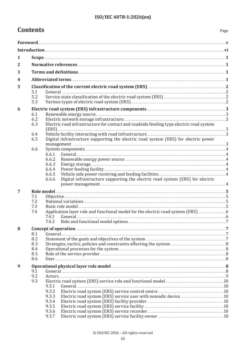
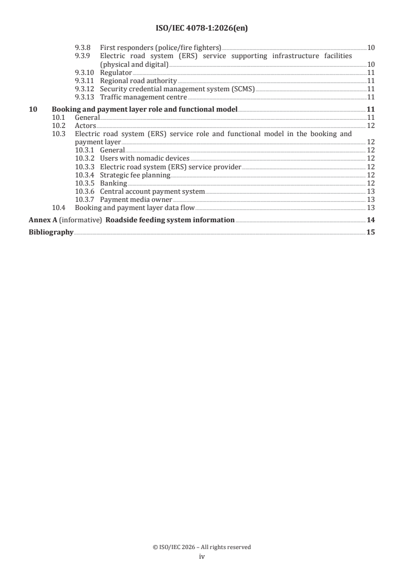
ISO/IEC 4078-1 is an ISO standard for the service role architecture of roadside feeding electric road systems (ERS). It specifies how an ERS with dynamic charging capability is organized for sustainable mobility and transportation, with a focus on roles, service layers, and the relationships between users, providers, road authorities, and certification bodies. The document is aimed at people who need a common model for conductive roadside feeding in intercity commercial electric vehicle transport.
What does ISO/IEC 4078-1 specify?
ISO/IEC 4078-1 specifies the role architecture of electric road systems (ERS) with dynamic charging capability. It concentrates on roadside feeding, the service roles around it, and the way the system is structured for use in sustainable mobility and transportation.
The scope is narrow on purpose. ISO/IEC 4078-1 excludes the in-vehicle control system and focuses on the roadside system boundary, so readers can use it to define interfaces, responsibilities, and service arrangements without mixing in vehicle design.
The document is organized into these main parts:
- Clause 5 - classification of the current ERS
- Clause 6 - ERS infrastructure components
- Clause 7 - role model
- Clause 8 - concept of operation
- Clause 9 - operational physical layer role model
- Clause 10 - booking and payment layer role and functional model
- Annex A - informative roadside feeding system information
What are the key requirements of ISO/IEC 4078-1?
ISO/IEC 4078-1 is mainly a system-architecture and role-model document. Its key points are about what the ERS contains, who does what, and how the service is operated and paid for.
1. The standard defines the ERS boundary around roadside feeding
Clause 1 limits the document to ERS with dynamic charging capability. Clause 6.3 and 6.4 keep the vehicle-side facility and the in-vehicle control system outside the scope, which means deployment teams must treat the roadside system and the vehicle system as separate design areas.
2. The document classifies ERS service states and types
Clause 5 introduces a service state classification and shows various types of ERS. Clause 5.2 and 5.3 help readers compare deployment options and choose the service configuration that fits a national or regional use case.
3. The infrastructure model includes power, storage, roadside equipment, and digital support
Clause 6 identifies renewable energy source, electric network storage infrastructure, electric road infrastructure for contact and roadside feeding type, vehicle facilities interacting with road infrastructure, and digital infrastructure supporting ERS for electric power management. In practice, this means an ERS is not only a feeding device at the roadside - it also depends on energy buffering and digital coordination.
4. The document expects renewable energy and storage to support operation
Clause 6.1 links the ERS power source to renewable sources where possible, and Clause 6.2 ties energy storage to demand surges and renewable variability. For implementers, this means the power architecture should smooth peaks and support stable operation while vehicles are charging on the move.
5. The feeding interface is defined as roadside conductive feeding
Clause 6.6.4 makes clear that the document applies to roadside feeding and contact type ERS. It also notes AC or DC supply and states that deployment must address abnormal conditions such as short circuits and ground faults, so safety handling is part of system planning rather than an afterthought.
6. The role model is adapted from a general ITS service model
Clause 7 uses a baseline role model and adapts it for ERS service applications. It also allows national variations, which matters because the same service can be organized differently by different jurisdictions while still following a common conceptual structure.
7. Certification and regulatory control are part of the architecture
Clause 7.4.3 and Clause 8 describe certification authority roles, service provider certification, and inspection of facilities according to regional authority regulations. In practice, an operator or supplier needs to know which body certifies the service, who audits it, and which local rules apply.
8. The operational model separates service delivery from booking and payment
Clause 9 describes the physical service roles, including the service control centre, facility provider, facility owner, inspection/certification authority, first responders, SCMS, and traffic management centre. Clause 10 then adds booking, banking, central account payment, strategic fee planning, and payment media ownership, so the commercial service flow is separate from the roadside technical flow.
What terms does ISO/IEC 4078-1 define?
ISO/IEC 4078-1 uses a set of abbreviations that frame the service and technology model.
- AC - alternating current, one of the supply forms named for roadside feeding.
- DC - direct current, the other supply form named for roadside feeding.
- BEV - battery electric vehicle, the vehicle type used in the introduction to motivate dynamic charging.
- CONOPS - concept of operations, the service-oriented view of how the system is used.
- ERS - electric road system, the main system covered by the document.
- ITS - intelligent transport system, the wider service environment in which the ERS roles are described.
- METR - management for electronic traffic regulations, a digital infrastructure service named in the physical role model.
- SCMS - security credential management system, the security component used for provisioning credentials in the ERS service.
Who uses ISO/IEC 4078-1?
ISO/IEC 4078-1 is used by organizations that plan, regulate, build, or operate roadside feeding systems for electric vehicles. It is especially relevant where the use case is intercity commercial transport and heavy-duty battery electric vehicles.
Typical users include:
- regional road authorities and municipal regulators
- ERS service providers and facility providers
- facility owners and inspection/certification authorities
- traffic management centres
- banking and payment service actors involved in booking and settlement
- fleet operators, logistics bodies, and goods transport users
- planners working on dynamic charging, smart city services, and ITS integration
These users use the standard to assign responsibilities, define interfaces, plan certification, and organize service delivery.
Which standards are used with ISO/IEC 4078-1?
ISO/IEC 4078-1 has no normative references, but the document names several related standards and companion parts.
- ISO 4078-2 - the future part on service and operational concept.
- ISO 4078-3 - the future part on system components.
- ISO/TR 4445 - the baseline role model used for ITS service applications in smart cities.
- ISO 15638-26:2024 - a related ITS document cited in the bibliography for electric vehicle dynamic charging monitoring.
These references show how ISO/IEC 4078-1 fits into a broader framework for ERS roles, operations, and monitoring.
What does the ISO/IEC 4078-1 document contain?
ISO/IEC 4078-1 contains a classification of ERS service states, a description of ERS infrastructure components, and a conceptual role model for service delivery. It also presents the operational concept from the viewpoint of the user and the service provider.
The document includes several figures that carry most of the technical structure:
- figures for service state classification and ERS types
- a figure for ERS system components
- a basic role model and an ERS application-layer role model
- an operational physical layer role model
- a booking and payment layer role model
- a booking and payment data flow diagram
Annex A is informative and gives roadside feeding system information, including a physical image of a contact-type roadside feeding ERS. The bibliography points readers to the companion parts of the ISO 4078 series and to related ITS and dynamic-charging references.
Get Certified
Connect with accredited certification bodies for this standard

BSI Group
BSI (British Standards Institution) is the business standards company that helps organizations make excellence a habit.

Bureau Veritas
Bureau Veritas is a world leader in laboratory testing, inspection and certification services.

DNV
DNV is an independent assurance and risk management provider.
Sponsored listings
Frequently Asked Questions
ISO/IEC 4078-1:2026 is a standard published by the International Organization for Standardization (ISO). Its full title is "Sustainable mobility and transportation — Roadside feeding electric road system — Part 1: Service role architecture". This standard covers: This document specifies the role architecture of electric road systems (ERS) with dynamic charging capability. The in-vehicle control system is not within the scope of this document.
This document specifies the role architecture of electric road systems (ERS) with dynamic charging capability. The in-vehicle control system is not within the scope of this document.
ISO/IEC 4078-1:2026 is classified under the following ICS (International Classification for Standards) categories: 03.220.20 - Road transport; 13.020.20 - Environmental economics. Sustainability. The ICS classification helps identify the subject area and facilitates finding related standards.
ISO/IEC 4078-1:2026 is available in PDF format for immediate download after purchase. The document can be added to your cart and obtained through the secure checkout process. Digital delivery ensures instant access to the complete standard document.
Standards Content (Sample)
International
Standard
ISO/IEC 4078-1
First edition
Sustainable mobility and
2026-11
transportation — Roadside feeding
electric road system —
Part 1:
Service role architecture
Mobilité et transport durables — Système routier électrique
d'alimentation en bordure de route —
Partie 1: Architecture des rôles de service
Reference number
© ISO/IEC 2026
All rights reserved. Unless otherwise specified, or required in the context of its implementation, no part of this publication may
be reproduced or utilized otherwise in any form or by any means, electronic or mechanical, including photocopying, or posting on
the internet or an intranet, without prior written permission. Permission can be requested from either ISO at the address below
or ISO’s member body in the country of the requester.
ISO copyright office
CP 401 • Ch. de Blandonnet 8
CH-1214 Vernier, Geneva
Phone: +41 22 749 01 11
Email: copyright@iso.org
Website: www.iso.org
Published in Switzerland
© ISO/IEC 2026 – All rights reserved
ii
Contents Page
Foreword .v
Introduction .vi
1 Scope . 1
2 Normative references . 1
3 Terms and definitions . 1
4 Abbreviated terms . 1
5 Classification of the current electric road system (ERS) . 2
5.1 General .2
5.2 Service state classification of the electric road system (ERS) .2
5.3 Various types of electric road system (ERS) .2
6 Electric road system (ERS) infrastructure components . 3
6.1 Renewable energy source .3
6.2 Electric network storage infrastructure .3
6.3 Electric road infrastructure for contact and roadside feeding type electric road system
(ERS) . .3
6.4 Vehicle facility interacting with road infrastructure .3
6.5 Digital infrastructure supporting the electric road system (ERS) for electric power
management .3
6.6 System components .4
6.6.1 General .4
6.6.2 Renewable energy power source .4
6.6.3 Energy storage .4
6.6.4 Power feeding facility .4
6.6.5 Vehicle side power receiving and feeding facilities .4
6.6.6 Digital infrastructure supporting the electric road system (ERS) for electric
power management .4
7 Role model . 5
7.1 Objective.5
7.2 National variations .5
7.3 Basic role model.5
7.4 Application layer role and functional model for the electric road system (ERS) .6
7.4.1 General .6
7.4.2 Role and functional model options .7
8 Concept of operation . 7
8.1 General .7
8.2 Statement of the goals and objectives of the system .7
8.3 Strategies, tactics, policies and constraints affecting the system .8
8.4 Operational processes for the system .8
8.5 Role of the service provider .8
8.6 User .8
9 Operational physical layer role model . 8
9.1 General .8
9.2 Actors .9
9.3 Electric road system (ERS) service role and functional model .10
9.3.1 General .10
9.3.2 Electric road system (ERS) service control centre .10
9.3.3 Electric road system (ERS) service user with nomadic device .10
9.3.4 Electric road system (ERS) facility provider .10
9.3.5 Electric road system (ERS) service facility .10
9.3.6 Electric road system (ERS) service recorder .10
9.3.7 Electric road system (ERS) service facility owner .10
© ISO/IEC 2026 – All rights reserved
iii
9.3.8 First responders (police/fire fighters) .10
9.3.9 Electric road system (ERS) service supporting infrastructure facilities
(physical and digital) .10
9.3.10 Regulator .11
9.3.11 Regional road authority .11
9.3.12 Security credential management system (SCMS) .11
9.3.13 Traffic management centre .11
10 Booking and payment layer role and functional model .11
10.1 General .11
10.2 Actors . 12
10.3 Electric road system (ERS) service role and functional model in the booking and
payment layer . 12
10.3.1 General . 12
10.3.2 Users with nomadic devices . 12
10.3.3 Electric road system (ERS) service provider . 12
10.3.4 Strategic fee planning. 12
10.3.5 Banking . 12
10.3.6 Central account payment system . 13
10.3.7 Payment media owner . 13
10.4 Booking and payment layer data flow . 13
Annex A (informative) Roadside feeding system information . 14
Bibliography .15
© ISO/IEC 2026 – All rights reserved
iv
Foreword
ISO (the International Organization for Standardization) and IEC (the International Electrotechnical
Commission) form the specialized system for worldwide standardization. National bodies that are
members of ISO or IEC participate in the development of International Standards through technical
committees established by the respective organization to deal with particular fields of technical activity.
ISO and IEC technical committees collaborate in fields of mutual interest. Other international organizations,
governmental and non-governmental, in liaison with ISO and IEC, also take part in the work.
The procedures used to develop this document and those intended for its further maintenance are described
in the ISO/IEC Directives, Part 1. In particular, the different approval criteria needed for the different types
of document should be noted. This document was drafted in accordance with the editorial rules of the ISO/
IEC Directives, Part 2 (see www.iso.org/directives or www.iec.ch/members_experts/refdocs).
ISO and IEC draw attention to the possibility that the implementation of this document may involve the
use of (a) patent(s). ISO and IEC take no position concerning the evidence, validity or applicability of any
claimed patent rights in respect thereof. As of the date of publication of this document, ISO and IEC had not
received notice of (a) patent(s) which may be required to implement this document. However, implementers
are cautioned that this may not represent the latest information, which may be obtained from the patent
database available at www.iso.org/patents and https://patents.iec.ch. ISO and IEC shall not be held
responsible for identifying any or all such patent rights.
Any trade name used in this document is information given for the convenience of users and does not
constitute an endorsement.
For an explanation of the voluntary nature of standards, the meaning of ISO specific terms and expressions
related to conformity assessment, as well as information about ISO's adherence to the World Trade
Organization (WTO) principles in the Technical Barriers to Trade (TBT) see www.iso.org/iso/foreword.html.
In the IEC, see www.iec.ch/understanding-standards.
This document was prepared by Joint Technical Committee ISO/IEC JTC 4, Smart and sustainable cities and
communities, Subcommittee SC 2, Sustainable Mobility and Transportation.
A list of all parts in the ISO/IEC 4078 series can be found on the ISO and IEC websites.
Any feedback or questions on this document should be directed to the user’s national standards
body. A complete listing of these bodies can be found at www.iso.org/members.html and
www.iec.ch/national-committees.
© ISO/IEC 2026 – All rights reserved
v
Introduction
Achieving carbon neutrality for heavy-duty commercial vehicles, which are responsible for intercity
commercial transport, is essential. Possible solutions include electric vehicles (EVs) and hydrogen vehicles.
Challenges exist in using battery electric vehicles (BEVs) for long haul intercity commercial transportation.
It is inefficient and uneconomical for an EV carrying a large battery to travel between cities while being
charged due to the time consumed for charging. Therefore, it is a wise measure to receive electricity from
the infrastructure while driving on the interurban corridor and charging the battery and obtaining driving
energy.
When running at the beginning and end of travelling, the vehicle can run as a pure EV and does not emit
carbon dioxide. It is known that various methods have already been developed around the world for charging
systems while driving; sometimes this is called “dynamic charging.” This means that the electrical power
system is for dynamic charging on highways.
The international standardization of contact-type roadside electric roads is described in this document.
Another point to consider is the elimination of carbon dioxide emissions. Electric vehicles should be powered
by renewable energy as much as possible. In addition, it is necessary to install power storage equipment to
smooth out the loading due to various changes in energy consumption.
Safety measures to avoid human body hazards from the power supply equipment are necessary on the
roadside. In addition, security measures against cyber-attacks are also necessary. It is necessary to
authenticate the rights of the power supply side and the power receiving side to avoid unauthorized energy
consumption by a third party which does not have access rights.
It is only when these measures are taken that a highly reliable electric road system (ERS) can be constructed.
The ISO 4078 series specifies the roadside ERS and related services supporting intercity commercial EV
transportation systems. This document defines a role and function model for the introduction of roadside
electric roads and related services to support intercity commercial EV transportation systems. ISO 4078-2
defines the service and operational concept and ISO 4078-3 defines the system component.
Because of the variety of role and function model presentation methodologies currently available, there
is a need for a more commonly understood set of role and function model presentation guidance and
requirements. This document defines the presentation of a generic roadside-powered electric road service
role and function model.
New business cases in the future can refer to this document as a baseline document. In fact, it is intended
to assist future business development, but not to hinder it. This document can also contribute to the
development of the business case for other future road system services, other than electric road services.
1) Under preparation. Stage at the time of publication: ISO/DIS 4078-3:2026.
© ISO/IEC 2026 – All rights reserved
vi
International Standard ISO/IEC 4078-1:2026(en)
Sustainable mobility and transportation — Roadside feeding
electric road system —
Part 1:
Service role architecture
1 Scope
This document specifies the role architecture of electric road systems (ERS) with dynamic charging
capability.
The in-vehicle control system is not within the scope of this document.
2 Normative references
There are no normative references in this document.
3 Terms and definitions
No terms and definitions are listed in this document.
ISO and IEC maintain terminology databases for use in standardization at the following addresses:
— ISO Online browsing platform: available at https:// www .iso .org/ obp
— IEC Electropedia: available at https:// www .electropedia .org/
4 Abbreviated terms
AC alternating current
AI artificial intelligence
BEV battery electric vehicle
CONOPS concept of operations
DC direct current
ERS electric road system
EV electric vehicle
ITS intelligent transport system
METR management for electronic traffic regulations
SCMS security credential management system
© ISO/IEC 2026 – All rights reserved
5 Classification of the current electric road system (ERS)
5.1 General
Carbon neutral transportation can be achieved by deploying non-ICE (internal combustion engine) heavy
vehicles such as BEVs.
To realize sustainable long-haul transportation by such vehicles, there is a need for ERS, which have dynamic
charging capabilities even while vehicles are on the move.
Dynamic charging systems need to be designed as whole eco-systems from upstream to downstream.
Defining the appropriate service role model architecture for such dynamic charging eco-system services in
sustainable mobility and transportation is indispensable in the form of International Standards.
5.2 Service state classification of the electric road system (ERS)
A simple service state classification for the ERS is described in Figure 1 as an example of variations. There
are various kinds of combinations of functions listed in Figure 1.
Figure 1 — ERS service state classifications
5.3 Various types of electric road system (ERS)
The various types of ERS are shown in Figure 2 below. This document aims to standardize conductive
(contact type) roadside feeding only and does not include other kinds to avoid obstructing the development
of other kinds.
© ISO/IEC 2026 – All rights reserved
NOTE The term “roadside” used in this document refers to the area adjacent to a road or highway. It can include
the shoulder, the median and the land on either side of the road. The advantage of using the roadside as power feeding
facilities is its simpler configuration compared to other methods.
Figure 2 — Various types of ERS
6 Electric road system (ERS) infrastructure components
6.1 Renewable energy source
The power source for t
...