

SIST IEC 60255-21-1:1995
(Main)Electrical relays - Part 21: Vibration, shock, bump and seismic tests on measuring relays and protection equipment - Section One: Vibration tests (sinusoidal)
- Abstract
This part includes two types of vibration tests: the vibration response test and the vibration endurance test, and is generally based upon IEC 68-2-6. The requirements are applicable only to measuring relays and protection equipment in a new condition. The tests specified are type tests.
- Status
- Published
- Publication Date
- 31-Jul-1995
- Technical Committee
- ISS EIT.ERE - All-or-nothing electrical relays
- Current Stage
- 6060 - National Implementation/Publication (Adopted Project)
- Start Date
- 01-Aug-1995
- Due Date
- 01-Aug-1995
- Completion Date
- 01-Aug-1995

SIST IEC 60255-21-1:1995 is the Slovenian adoption of IEC 60255-21-1 for electrical relays. It specifies sinusoidal vibration tests for measuring relays and protection equipment, including a vibration response test and a vibration endurance test, for equipment in new condition and for type testing.
What does SIST IEC 60255-21-1:1995 specify?
SIST IEC 60255-21-1:1995 specifies the vibration test methods, test conditions, severity classes, and acceptance criteria for measuring relays and protection equipment, with or without contacts. The document is organized into Scope, Object, Definitions, Requirements for vibration tests, Criteria for acceptance, and Appendix A.
| Part of the document | What it covers |
|---|---|
| Clause 1 | Scope and applicability |
| Clause 2 | Purpose of the standard |
| Clause 3 | Definitions used in the tests |
| Clause 4 | Test apparatus, mounting, severity classes, and procedure |
| Clause 5 | Acceptance criteria |
| Appendix A | Output circuit response during vibration response testing |
The standard is generally based on IEC 68-2-6. In practice, this means the vibration method and much of the terminology follow the wider IEC environmental testing approach.
What are the key requirements of SIST IEC 60255-21-1:1995?
SIST IEC 60255-21-1:1995 sets out the test setup so that the specimen sees controlled sinusoidal vibration along one axis at a time, then in the other axes in turn. Clause 4.1 limits transverse motion, distortion, amplitude tolerance, frequency tolerance, and sweep rate so the applied vibration stays close to the declared test conditions.
Test apparatus and mounting
Clause 4.1 requires the specimen to be mounted by its normal means of attachment and in the same gravitational orientation as in service. This matters because the test should reflect real installation conditions, not a special laboratory mounting.
Clause 4.1.7 also says cable connections during the vibration response test must not add more restraint or mass than they would in actual use. That prevents the wiring from hiding a problem or creating one that would not exist in service.
Severity classes
Clause 4.2 defines three severity classes for both tests. Class 0 means no vibration tests apply, Class 1 is for normal use and transport conditions, and Class 2 is for higher vibration levels, including severe transport or shipboard use.
For the vibration response test, Clause 4.2.1 sets the frequency range at 10 Hz to 150 Hz and uses classes distinguished by peak displacement and peak acceleration. For the vibration endurance test, Clause 4.2.2 uses the same nominal frequency range with constant acceleration and classes based on acceleration and number of sweep cycles.
Test procedure and acceptance
Clause 4.3 separates the vibration response test from the vibration endurance test. The response test is performed on energized equipment under reference conditions, while the endurance test is performed with the equipment not energized.
Clause 5.1 requires no maloperation during the response test, no permanent change of flags or indicators, and no mechanical damage after the test. The setting must also stay within the stated limit, so the test checks both immediate behavior and post-test performance.
Clause 5.2 allows flags or indicators to change state during the endurance test, but the equipment must still meet its performance specification afterward and remain free of mechanical damage. Appendix A adds guidance for equipment with very short operating times and recommends declaring the peak vibration levels for which no unwanted output-circuit change of state occurs.
What terms does SIST IEC 60255-21-1:1995 define?
- Vibration test (sinusoidal) - A test in which the specimen is swept through sinusoidal vibration along the three specimen axes in turn.
- Vibration response test - A test on energized equipment to see how it responds under normal service conditions.
- Vibration endurance test - A test on non-energized equipment at higher vibration levels to simulate long-term vibration and some transport conditions.
- Fixing point - The part of the specimen that contacts the fixture or vibration table where it is normally fastened in service.
- Reference point - The measuring point chosen to control the test so the required conditions are maintained.
- Cross-over frequency - The frequency where the test characteristic changes from constant displacement to constant acceleration.
- Standard acceleration of gravity (g_n) - The standard value of gravity, 9.81 m/s², often rounded to 10 m/s² in practice.
Who uses SIST IEC 60255-21-1:1995?
SIST IEC 60255-21-1:1995 is used by manufacturers of measuring relays and protection equipment, test laboratories, and engineering teams that qualify products for vibration service. Quality managers and buyers use it when they need a defined type test for equipment intended for substations, power plants, industrial plants, transportation, or other vibration-sensitive installations.
It is also useful for packaging and transport planning, because the severity classes link the test level to the conditions the equipment is expected to withstand.
Which standards are used with SIST IEC 60255-21-1:1995?
SIST IEC 60255-21-1:1995 cites IEC 50, the International Electrotechnical Vocabulary, for general terms. It cites IEC 68-2-6 for the basic sinusoidal vibration testing approach.
It also cites the IEC 255 series for relay-related terms and reference conditions, and IEC 255-7 for related test and measurement procedures. ISO 2041 is cited for vibration and shock vocabulary.
What does the SIST IEC 60255-21-1:1995 document contain?
The document contains definitions, test conditions, severity classes, procedures, and acceptance criteria for sinusoidal vibration testing. It includes tables for the response and endurance severity classes and a guide to selecting a class for different applications.
Clause 4 describes the vibration generator, mounting, sweep method, and measurement points used to control the test. Clause 5 gives the pass-fail criteria, including output-circuit behavior, indicator behavior, setting shift, and mechanical damage checks.
Appendix A discusses output circuit response during vibration response testing and explains why very short change-of-state times may need special consideration.
Relations
- Effective Date
- 05-Sep-2023
Get Certified
Connect with accredited certification bodies for this standard

IMQ S.p.A. (Certification)
Italian electrical product certification.

SLG Prüf- und Zertifizierungs GmbH
German testing and certification body.

UL Solutions
Global safety science company with testing, inspection and certification.
Sponsored listings
Frequently Asked Questions
SIST IEC 60255-21-1:1995 is a standard published by the Slovenian Institute for Standardization (SIST). Its full title is "Electrical relays - Part 21: Vibration, shock, bump and seismic tests on measuring relays and protection equipment - Section One: Vibration tests (sinusoidal)". This standard covers: This part includes two types of vibration tests: the vibration response test and the vibration endurance test, and is generally based upon IEC 68-2-6. The requirements are applicable only to measuring relays and protection equipment in a new condition. The tests specified are type tests.
This part includes two types of vibration tests: the vibration response test and the vibration endurance test, and is generally based upon IEC 68-2-6. The requirements are applicable only to measuring relays and protection equipment in a new condition. The tests specified are type tests.
SIST IEC 60255-21-1:1995 is classified under the following ICS (International Classification for Standards) categories: 29.120.40 - Switches; 29.120.70 - Relays. The ICS classification helps identify the subject area and facilitates finding related standards.
SIST IEC 60255-21-1:1995 has the following relationships with other standards: It is inter standard links to SIST IEC 60255-21-2:1995. Understanding these relationships helps ensure you are using the most current and applicable version of the standard.
SIST IEC 60255-21-1:1995 is available in PDF format for immediate download after purchase. The document can be added to your cart and obtained through the secure checkout process. Digital delivery ensures instant access to the complete standard document.
Standards Content (Sample)
SLOVENSKI STANDARD
01-avgust-1995
Electrical relays - Part 21: Vibration, shock, bump and seismic tests on measuring
relays and protection equipment - Section 1: Vibration tests (sinusoidal)
Electrical relays - Part 21: Vibration, shock, bump and seismic tests on measuring relays
and protection equipment - Section One: Vibration tests (sinusoidal)
Relais électriques - Vingt et unième partie: Essais de vibrations, de chocs, de secousses
et de tenue aux séismes applicables aux relais de mesure et aux dispositifs de protection
- Section un: Essais de vibrations (sinusoïdales)
Ta slovenski standard je istoveten z: IEC 60255-21-1
ICS:
29.120.70 Releji Relays
2003-01.Slovenski inštitut za standardizacijo. Razmnoževanje celote ali delov tega standarda ni dovoljeno.
NORME CEI
INTERNATIONALE IEC
255-21-1
INTERNATIONAL
Première édition
STAN DARD
First edition
Relais électriques
Vingt et unième partie:
Essais de vibrations, de chocs, de secousses et de
tenue aux séismes applicables aux relais de mesure
et aux dispositifs de protection
Section un — Essais de vibrations (sinusoïdales)
Electrical relays
Part 21:
Vibration, shock, bump and seismic test on
measuring relays and protection equipment
Section One — Vibration tests (sinusoidal)
de reproduction réservés —Copyright - all rights reserved
© CEI 1988 Droits
ne peut être reproduite ni No part of this publication may be reproduced or utilized
Aucune partie de cette publication
que ce soit et par aucun procédé, in any form or by any means, electronic or mechanical,
utilisée sous quelque forme
photocopie et les including photocopying and microfilm, without permission
électronique ou mécanique, y compris la
in writing from the publisher
microfilms, sans l'accord écrit de l'éditeur.
rnationale 3, rue de Varembé Genève Suisse
Bureau central de la Commission Electrotechnique Inte
Commission Electrotechnique Internationale CODE PRIX
L
International Electrotechnical Commission PRICE CODE
IEC
HOMHCCHN
MemayHapoiaHae 3nettTpoTexuH4ecnaR
• Pour prix, voir catalogue en vigueur
For price, see current catalogue
255-21-1 (1) © IEC - 3
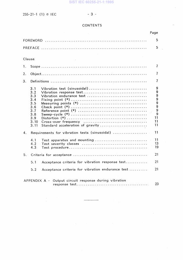
CONTENTS
Page
FOREWORD 5
PREFACE 5
Clause _
1. Scope 7
2. Object 7
3 Definitions
3.1 Vibration test (sinusoidal)
3.2 Vibration response test
3.3 Vibration endurance test
3.4 Fixing point (*) 9
9 3.5 Measuring points (*)
3.6 Check point (*)
Reference point (*) 3.7
3.8 Sweep-cycle (*) 9
3.9 Distortion (*)
3.10 Cross-over frequency
3.11 Standard acceleration of gravity
4. Requirements for vibration tests (sinusoidal)
Test apparatus and mounting 4.1
13 4.2 Test severity classes
19 4.3 Test procedure
5. Criteria for acceptance
5.1 Acceptance criteria for vibration response test
5.2 Acceptance criteria for vibration endurance test
APPENDIX A - Output circuit response during vibration
response test
255-21-1 (1) © IEC - 5 -
INTERNATIONAL ELECTROTECHNICAL COMMISSION
ELECTRICAL RELAYS
Part 21: Vibration, shock, bump and seismic tests on
measuring relays and protection equipment
Section One: Vibration tests (sinusoidal)
FOREWORD
1) The formal decisions or agreements of the IEC on technical matters, prepared by Technical
Committees on which all the National Committees having a special interest therein are
represented, express, as nearly as possible, an international consensus of opinion on the
subjects dealt with.
2) They have the form of recommendations for international use and they are accepted by the
National Committees in that sense.
3)
In order to promote international unification, the IEC expresses the wish that all
National Committees should adopt the text of the IEC recommendation for their national
rules in so far as national conditions will permit. Any divergence between the IEC
recommendation and the corresponding national rules should, as far as possible, be clearly
indicated in the latter.
PREFACE
This standard has been prepared by Sub-Committee 41B: Measuring
Relays and Protection Equipment, of IEC Technical Committee No. 41:
Electrical relays.
The text of this standard is based on the following documents:
Six Months' Rule Report on Voting
41B(C0)35 41B(CO)37
Full information on the voting for the approval of this standard can be
found in the Voting Report indicated in the above table.
The following IEC publications are quoted in this standard:
Publications Nos. 50: International Electrotechnical Vocabulary (IEV).
68-2-6 (1982): Basic environmental testing procedures, Part 2: Tests. Test Fc and
guidance: Vibration (sinusoidal).
255: Electrical relays.
255-7 (1978): Part 7: Test and measurement procedures for electromechanical
all-or-nothing relays.
Other publication quoted:
ISO 2041-1975: Vibration and shock - Vocabulary.
©
255-21-1 (1) IEC - 7 -
ELECTRICAL RELAYS
Vibration, shock, bump and seismic tests on
Part 21:
measuring relays and protection equipment
Section One: Vibration tests (sinusoidal)
1. Scope
This standard is part of a series specifying the vibration, shock,
bump and seismic requirements applicable to measuring relays and
protection equipment (with or without contacts).
This standard includes two types of vibration tests: the vibration
response test and the vibration endurance test, and is generally based
upon IEC 68-2-6.
The requirements of this standard are applicable only to measuring
relays and protection equipment in a new condition.
The tests specified in this standard are type tests.
2. Object
The object of this standard is to state:
- definitions of terms used;
- test conditions;
- standard test severity classes;
- test procedure;
- criteria for acceptance.
3. Definitions
For definitions of general terms not defined in this standard,
reference should be made to:
- International Electrotechnical Vocabulary (IEV) [IEC 50];
- IEC 68-2 -6;
- relay standards published in the IEC 255 series;
- ISO 2041
For the purpose of this standard the following definitions shall
apply.
Note.- Definitions marked with (*) are derived from IEC 68-2-6.
255-21-1 (1) © IEC - 9
3.1 Vibration test (sinusoidal)
A test during which a specimen is submitted to sweeps of sinusoidal
vibration in the three different axes of the specimen in turn, in terms
of constant displacement and/or constant acceleration, within a stan-
dard frequency range.
The term "specimen" includes any auxiliary part which is an
Note. -
integral functional feature of the measuring relay or protection
equipment under test.
3.2 Vibration response test
A vibration test carried out on a measuring relay or protection
equipment, energized under specified conditions, to determine its
response to normal service conditions.
3.3 Vibration endurance test
A vibration test carried out on a non-energized measuring relay or
protection equipment, with higher vibration levels than in normal
service conditions, as an accelerated life test to simulate long-term
vibration. This test also simulates some transportation conditions.
3.4 Fixing point (*)
Part of the specimen in contact with the fixture or vibration table at
a point where the specimen is normally fastened in service.
If a part of the real mounting structure is used as the fixture, the
fixing points shall be taken as those of the mounting structure and not
of the specimen.
3.5 Measuring points (*)
The specific points at which data are obtained during the tests.
They are of two main types: check point and reference point.
3.6 Check point (*)
A measuring point located on the fixture, on the vibration table or
on the specimen as close as possible and rigidly connected to one of
its fixing points.
3.7 Reference point (*)
A measuring point chosen from the check points whose signal is used
to control the test so that the requirements of this standard are
satisfied.
3.8 Sweep-cycle (*)
A traverse of the specified frequency range once in each direction,
150 Hz to 10 Hz.
for example 10 Hz to 150 Hz and
255-21-1 (1) © IEC - 11 -
3.9 Distortion (*)
2 2
a
tot - ai
V
x 100 (percentage)
Distortion d =
ai
where:
a^ r.m.s. value of the acceleration at the driving frequency
total r.m.s. value of the applied acceleration
a tot
(including the value of al)
3.10 Cross-over frequency
That frequency at which the characteristic of a vibration changes
from a constant displacement value versus frequency to a constant'
acceleration value versus frequency.
3.11 Standard acceleration of gravity
The standard acceleration of gravity g n , where "n" indicates normal,
having the value of 9.81 m/s 2 . In practice this value may be rounded
to 10 m/s2.
4. Requirements for vibration tests (sinusoidal)
The main parameters of the vibration tests are the following:
- frequency range;
- acceleration;
- displacement amplitude below the cross-over frequency, if any,
sweep rate and number of sweep cycles.
4.1 Test apparatus and mounting
The required characteristics of the vibration generator and fixture
together with the mounting requirements shall be as follows. The
characteristics apply when the specimen is mounted on the generator.
4.1 .1
Basic motion
The basic motion shall be a sinusoidal function of time and such that
the fixing points of the specimen move substantially in phase and in
straight parallel lines along a specified axis, subjected to the
limitations of Sub-clauses 4.1.2 and 4.1.3.
4.1.2
Transverse motion
The maximum vibration amplitude at the check points in any axis
perpendicular to the specified axis shall not exceed 50% of the speci-
fied amplitude for basis motion.
255-21-1 (1) © IEC - 13 -
4.1.3
Distortion
The acceleration distortion measurement shall be carried out at the
reference point, which shall be declared by the manufacturer, and
shall cover the frequencies up
...