

oSIST prEN IEC 63609-2:2026
(Main)Thermal design of electronics assemblies with miniaturised surface mounting devices and related measurements
- Status
- Not Published
- Public Enquiry End Date
- 30-Nov-2026
- Technical Committee
- ITIV - Electronics assembly technology and Environmental standardization
- Current Stage
- 4020 - Public enquire (PE) (Adopted Project)
- Start Date
- 23-Sep-2026
- Due Date
- 10-Feb-2027

oSIST prEN IEC 63609-2:2026 is the Slovene standard published by SIST for thermal design of electronics assemblies with miniaturised surface mounting devices. It specifies a method for evaluating the in-plane and thickness thermal conductivities of polymer-composite circuit boards such as FR-4 and CEM-3, using finite element analysis with representative volume element (RVE) models and verification measurements. Engineers, test laboratories and suppliers use it to model board heat flow and compare calculated results with measured values.
What does oSIST prEN IEC 63609-2:2026 specify?
oSIST prEN IEC 63609-2:2026 specifies a thermal-conductivity evaluation method for circuit boards made of polymer composites. The focus is on boards used in electronics assemblies where board heat dissipation matters, and on the two directions that matter in practice - in-plane and thickness.
The document applies to boards with thermal conductivities from 0,1 W·m^-1·K^-1 to 10 W·m^-1·K^-1 and thicknesses from 0,5 mm to 3,0 mm. It explains how to build an RVE model, how to calculate conductivity with finite element analysis (FEA), and how to verify the results with measurement methods.
| Annex | What it covers |
|---|---|
| Annex A | Density and specific heat capacity measurements |
| Annex B | Methods for measuring thermal conductivity |
| Annex C | Finite element analysis of thermal conductivity using RVE models |
The document is organized into the foreword, introduction, Clause 1 to Clause 7, and three informative annexes. Clause 1 gives the scope, Clause 2 lists normative references, Clause 3 gives terms and definitions, Clauses 4 to 6 cover apparatus, procedure and verification, and Clause 7 sets out the report content.
What are the key requirements of oSIST prEN IEC 63609-2:2026?
oSIST prEN IEC 63609-2:2026 is built around a model-and-measure approach. In practice, the standard asks users to describe the board structure, calculate conductivity in simulation, and then check that result against a suitable measurement method.
Clause 4 - apparatus for analysis
Clause 4 expects a computer system capable of running the analysis, with a high-speed CPU, 64 GB or more of memory, and a graphics card such as the NVIDIA RTX series. It also recommends large storage capacity, with 5 TB or more suggested for analysis data.
This matters because the workflow is computationally heavy. If the workstation is undersized, model creation and mesh calculations become slow or impractical.
Clause 5.1 and 5.2 - inputs for the model
Clause 5.1 requires geometric parameters for the reinforcement to be taken from cross-section observation, such as scanning electron microscope photographs. For FR-4, the document uses the plain-weave glass-fibre structure; for CEM-3, it uses a plain-weave layer plus a non-weave layer.
Clause 5.2 requires the thermal conductivities of the constituent materials, such as the reinforcement and matrix materials. This matters because the model is only as good as the material data and geometry used to build it.
Clause 5.3 - RVE model creation
Clause 5.3 explains how to create the RVE model from the reinforcement geometry and constituent-material properties. For FR-4, the warp and weft yarns are treated as homogenised composite materials, and the document uses the rule of mixtures to estimate longitudinal and transverse conductivity.
For CEM-3, the plain-weave and non-weave layers are handled separately and then represented with equivalent properties. In practice, this means the user has to model the layered structure rather than treating the board as a uniform solid.
Clause 5.4 and 5.5 - finite element setup and calculation
Clause 5.4 sets out the meshing and boundary conditions. The RVE model should use conforming tetrahedral meshing where possible, while voxel meshing with brick elements is allowed for more complex models. Periodic symmetry is applied, and heat flow is imposed in the direction of interest.
Clause 5.5 then calculates thermal conductivity from heat flux, distance and temperature difference using Fourier’s law. This makes the calculation traceable: the output comes from the simulated heat flow through the model, not from a black-box estimate.
Clause 6.1 - verification in the thickness direction
Clause 6.1 requires measurement of thickness-direction conductivity using the steady-state method. At least three specimens are prepared, with thicknesses between 0,5 mm and 3,0 mm, and the document recommends removing the copper foil by etching before measurement.
The measurement result is evaluated from the relationship between thermal resistance and specimen thickness, then compared with the FEA result from the RVE model. In practice, this gives a cross-check on whether the simulated thickness conductivity is credible.
Clause 6.2 - verification in the in-plane direction
Clause 6.2 requires in-plane conductivity to be measured using the laser flash method on lamellar specimens. The document notes that for composite circuit boards the thermal diffusivity obtained is an apparent value, so the result is used for relative comparison.
The specimen is made by cutting etched board strips and bonding them so that the in-plane direction becomes the thickness direction of the test piece. The measured thermal conductivity is then compared with the FEA result, which lets the user judge whether the model represents the board structure well enough.
Clause 7 - report content
Clause 7 requires the report to identify the calculation and measurement date, the operator, the material used, the software name, version and vendor, the reinforcement geometry, the constituent-material conductivities, the mesh size, the calculated in-plane and thickness conductivities, and the thermal-conductivity tester used together with the measured values.
That matters because the report is the record that links the simulation, the specimen and the measurement together. It is the document you would use in design reviews, audits or supplier discussions.
What terms does oSIST prEN IEC 63609-2:2026 define?
oSIST prEN IEC 63609-2:2026 defines the core analysis terms used in the method and also uses a few key technical terms repeatedly.
- Representative volume element (RVE) - the smallest volume that can represent the whole material response, often called a unit cell in composite materials.
- Finite element analysis (FEA) - a numerical method that divides an object into finite elements and solves the governing equations on that mesh.
- Steady-state method - a thermal-conductivity measurement method that uses a constant heat flow and the measured temperature difference across the specimen.
- Laser flash method - a thermal-diffusivity method that measures the backside temperature rise after a short laser pulse on the specimen surface.
- FR-4 - a polymer-composite circuit-board material used in the document as an example board structure for modelling and verification.
- CEM-3 - another polymer-composite circuit-board material used in the document, with separate plain-weave and non-weave layers.
- Lamellar specimen - a test specimen made by stacking strips so that the in-plane direction is measured through the thickness.
Who uses oSIST prEN IEC 63609-2:2026?
oSIST prEN IEC 63609-2:2026 is used by electronics-assembly engineers, thermal-design engineers, and materials engineers who need board conductivity data for simulation. It is also used by test laboratories that prepare specimens and run steady-state or laser-flash measurements.
Quality managers and buyers can use it to check whether a supplier’s conductivity claims were developed with a traceable method. Manufacturers of FR-4, CEM-3 and similar boards can use it to document thermal properties for product development and comparison.
What changed in oSIST prEN IEC 63609-2:2026 from the previous edition?
oSIST prEN IEC 63609-2:2026 supersedes 91/2079/CD and 91/2117/CC.
Which standards are used with oSIST prEN IEC 63609-2:2026?
The document cites IEC 60194-1 and IEC 60194-2 as normative references. These supply the common vocabulary used for circuit boards and electronic assembly technologies, so the terms in Clauses 1 to 7 are used consistently.
The foreword also places the document within the IEC 63609 series, alongside IEC 63609-1 and IEC 63609-3. Those parts cover thermal design guidance for applications where heat dissipation to the board is dominant, and temperature measurement in miniaturised surface mounting devices using thermocouples.
What does the oSIST prEN IEC 63609-2:2026 document contain?
oSIST prEN IEC 63609-2:2026 contains a practical calculation-and-verification method for polymer-composite circuit boards. It includes apparatus guidance, step-by-step model construction, meshing and boundary-condition rules, the conductivity calculation approach, verification procedures for thickness and in-plane directions, and the required report items.
The informative annexes add worked examples and supporting methods. Annex A gives example density and specific heat capacity measurements, Annex B shows steady-state and laser-flash measurement setups, and Annex C presents FEA examples for FR-4 and CEM-3, including figures, tables and comparison results.
Frequently Asked Questions
oSIST prEN IEC 63609-2:2026 is a draft published by the Slovenian Institute for Standardization (SIST). Its full title is "Thermal design of electronics assemblies with miniaturised surface mounting devices and related measurements". This standard covers: Thermal design of electronics assemblies with miniaturised surface mounting devices and related measurements
Thermal design of electronics assemblies with miniaturised surface mounting devices and related measurements
oSIST prEN IEC 63609-2:2026 is classified under the following ICS (International Classification for Standards) categories: 31.180 - Printed circuits and boards; 31.190 - Electronic component assemblies. The ICS classification helps identify the subject area and facilitates finding related standards.
oSIST prEN IEC 63609-2:2026 is available in PDF format for immediate download after purchase. The document can be added to your cart and obtained through the secure checkout process. Digital delivery ensures instant access to the complete standard document.
Standards Content (Sample)
SLOVENSKI STANDARD
01-november-2026
Toplotno načrtovanje elektronskih sklopov z miniaturiziranimi napravami za
površinsko montažo in s tem povezane meritve
Thermal design of electronics assemblies with miniaturised surface mounting devices
and related measurements
Ta slovenski standard je istoveten z: prEN IEC 63609-2:2026
ICS:
31.180 Tiskana vezja (TIV) in tiskane Printed circuits and boards
plošče
31.190 Sestavljeni elektronski Electronic component
elementi assemblies
2003-01.Slovenski inštitut za standardizacijo. Razmnoževanje celote ali delov tega standarda ni dovoljeno.
91/2127/CDV
COMMITTEE DRAFT FOR VOTE (CDV)
PROJECT NUMBER:
IEC 63609-2 ED1
DATE OF CIRCULATION: CLOSING DATE FOR VOTING:
2026-09-18 2026-12-11
SUPERSEDES DOCUMENTS:
91/2079/CD, 91/2117/CC
IEC TC 91 : ELECTRONICS ASSEMBLY TECHNOLOGY
SECRETARIAT: SECRETARY:
Japan Mr Osamu IKEDA
OF INTEREST TO THE FOLLOWING COMMITTEES: HORIZONTAL FUNCTION(S):
TC 40,TC 47,SC 47A,SC 47D
ASPECTS CONCERNED:
SUBMITTED FOR CENELEC PARALLEL VOTING NOT SUBMITTED FOR CENELEC PARALLEL VOTING
Attention IEC-CENELEC parallel voting
The attention of IEC National Committees, members of
CENELEC, is drawn to the fact that this Committee Draft
for Vote (CDV) is submitted for parallel voting.
The CENELEC members are invited to vote through the
CENELEC online voting system.
This document is still under study and subject to change. It should not be used for reference purposes.
Recipients of this document are invited to submit, with their comments, notification of any relevant patent rights of
which they are aware and to provide supporting documentation.
Recipients of this document are invited to submit, with their comments, notification of any relevant “In Some
Countries” clauses to be included should this proposal proceed. Recipients are reminded that the CDV stage is
the final stage for submitting ISC clauses. (SEE AC/22/2007 OR NEW GUIDANCE DOC).
TITLE:
Thermal design of electronics assemblies with miniaturised surface mounting devices and
related measurements - Part 2: Method for evaluating thermal conductivity of circuit boards
with polymer composites by using finite element analysis and measurements
PROPOSED STABILITY DATE: 2032
NOTE FROM TC/SC OFFICERS:
download this electronic file, to make a copy and to print out the content for the sole purpose of preparing National
Committee positions. You may not copy or "mirror" the file or printed version of the document, o r any part of it, for
any other purpose without permission in writing from IEC.
IEC CDV 63609-2 © IEC 2026
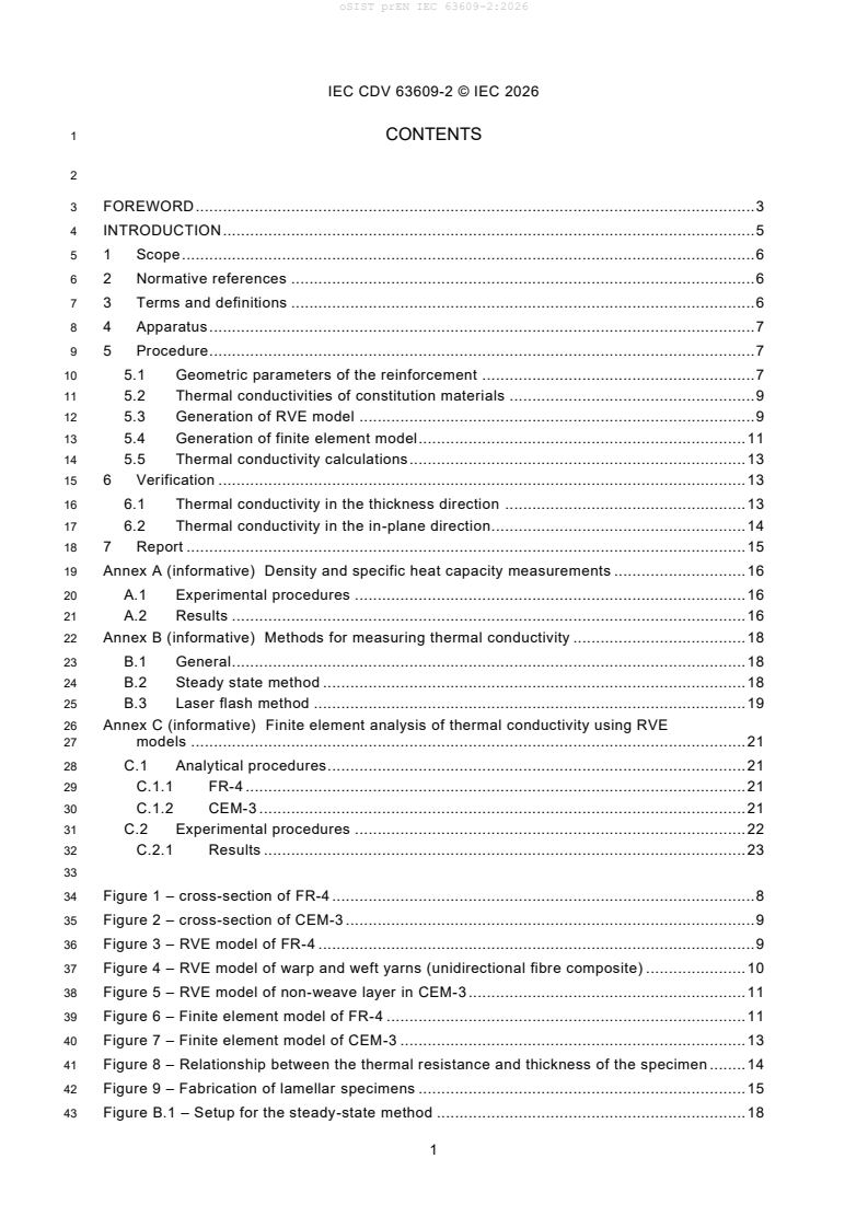
1 CONTENTS
3 FOREWORD . 3
4 INTRODUCTION . 5
5 1 Scope . 6
6 2 Normative references . 6
7 3 Terms and definitions . 6
8 4 Apparatus . 7
9 5 Procedure . 7
10 5.1 Geometric parameters of the reinforcement . 7
11 5.2 Thermal conductivities of constitution materials . 9
12 5.3 Generation of RVE model . 9
13 5.4 Generation of finite element model. 11
14 5.5 Thermal conductivity calculations . 13
15 6 Verification . 13
16 6.1 Thermal conductivity in the thickness direction . 13
17 6.2 Thermal conductivity in the in-plane direction. 14
18 7 Report . 15
19 Annex A (informative) Density and specific heat capacity measurements . 16
20 A.1 Experimental procedures . 16
21 A.2 Results . 16
22 Annex B (informative) Methods for measuring thermal conductivity . 18
23 B.1 General . 18
24 B.2 Steady state method . 18
25 B.3 Laser flash method . 19
26 Annex C (informative) Finite element analysis of thermal conductivity using RVE
27 models . 21
28 C.1 Analytical procedures. 21
29 C.1.1 FR-4 . 21
30 C.1.2 CEM-3 . 21
31 C.2 Experimental procedures . 22
32 C.2.1 Results . 23
34 Figure 1 – cross-section of FR-4 . 8
35 Figure 2 – cross-section of CEM-3 . 9
36 Figure 3 – RVE model of FR-4 . 9
37 Figure 4 – RVE model of warp and weft yarns (unidirectional fibre composite) . 10
38 Figure 5 – RVE model of non-weave layer in CEM-3 . 11
39 Figure 6 – Finite element model of FR-4 . 11
40 Figure 7 – Finite element model of CEM-3 . 13
41 Figure 8 – Relationship between the thermal resistance and thickness of the specimen . 14
42 Figure 9 – Fabrication of lamellar specimens . 15
43 Figure B.1 – Setup for the steady-state method . 18
IEC CDV 63609-2 © IEC 2026
44 Figure B.2 – Setup for the laser flash method . 19
45 Figure B.3 – Temperature rise versus time curve . 20
46 Figure C.1 – Experimental thermal conductivities in the thickness direction of neat FR-
47 4 obtained by steady-state method with single and multiple specimen techniques . 23
48 Figure C.2 – Experimental and analytical thermal conductivities in the thickness
49 direction of neat FR-4 . 24
50 Figure C.3 – Experimental and analytical thermal conductivities in the in-plane
51 direction of neat FR-4 . 24
52 Figure C.4 – Experimental and analytical thermal conductivities in the thickness
53 direction of neat CEM-3 (R1786) . 24
54 Figure C.5 – Experimental and analytical thermal conductivities in the in-plane
55 direction of neat CEM-3 (R1786) . 25
57 Table A.1 – Specific heat capacity and density of CEM-3 CCL and FR-4 CCL . 16
58 Table A.2 – Specific heat capacity and density of neat CEM-3 and neat FR-4 . 17
59 Table C.1 – Thermal conductivity of constitution materials in FR-4. 21
60 Table C.2 – Thermal conductivity of constitution materials in CEM-3. 22
IEC CDV 63609-2 © IEC 2026
80 INTERNATIONAL ELECTROTECHNICAL COMMISSION
81 ____________
83 THERMAL DESIGN OF ELECTRONICS ASSEMBLIES WITH MINIATURISED
84 SURFACE MOUNTING DEVICES AND RELATED MEASUREMENTS
86 Part 2: Method for evaluating thermal conductivity of circuit boards with
87 polymer composites by using finite element analysis and measurements
91 FOREWORD
92 1) The International Electrotechnical Commission (IEC) is a worldwide organization for standardization comprising
93 all national electrotechnical committees (IEC National Committees). The object of IEC is to promote international
94 co-operation on all questions concerning standardization in the electrical and electronic fields. To this end and
95 in addition to other activities, IEC publishes International Standards, Technical Specifications, Technical Reports,
96 Publicly Available Specifications (PAS) and Guides (hereafter referred to as "IEC Publication(s)"). Their
97 preparation is entrusted to technical committees; any IEC National Committee interested in the subject dealt with
98 may participate in this preparatory work. International, governmental and non-governmental organizations liaising
99 with the IEC also participate in this preparation. IEC collaborates closely with the International Organization for
100 Standardization (ISO) in accordance with conditions determined by agreement between the two organizations.
101 2) The formal decisions or agreements of IEC on technical matters express, as nearly as possible, an international
102 consensus of opinion on the relevant subjects since each technical committee has representation from all
103 interested IEC National Committees.
104 3) IEC Publications have the form of recommendations for international use and are accepted by IEC National
105 Committees in that sense. While all reasonable efforts are made to ensure that the technical content of IEC
106 Publications is accurate, IEC cannot be held responsible for the way in which they are used or for any
107 misinterpretation by any end user.
108 4) In order to promote international uniformity, IEC National Committees undertake to apply IEC Publications
109 transparently to the maximum extent possible in their national and regional publications. Any divergence between
110 any IEC Publication and the corresponding national or regional publication shall be clearly indicated in the latter.
111 5) IEC itself does not provide any attestation of conformity. Independent certification bodies provide conformity
112 assessment services and, in some areas, access to IEC marks of conformity. IEC is not responsible for any
113 services carried out by independent certification bodies.
114 6) All users should ensure that they have the latest edition of this publication.
115 7) No liability shall attach to IEC or its directors, employees, servants or agents including individual experts and
116 members of its technical committees and IEC National Committees for any personal injury, property damage or
117 other damage of any nature whatsoever, whether direct or indirect, or for costs (including legal fees) and
118 expenses arising out of the publication, use of, or reliance upon, this IEC Publication or any other IEC
119 Publications.
120 8) Attention is drawn to the Normative references cited in this publication. Use of the referenced publications is
121 indispensable for the correct application of this publication.
122 9) IEC draws attention to the possibility that the implementation of this document may involve the use of (a)
123 patent(s). IEC takes no position concerning the evidence, validity or applicability of any claimed patent rights in
124 respect thereof. As of the date of publication of this document, IEC had received notice of (a) patent(s), which
125 may be required to implement this document. However, implementers are cautioned that this may not represent
126 the latest information, which may be obtained from the patent database available at https://patents.iec.ch. IEC
127 shall not be held responsible for identifying any or all such patent rights.
128 IEC 63609-2 has been prepared by IEC technical committee 91: Electronics assembly
129 technology. It is an International Standard.
130 The text of this International Standard is based on the following documents:
IEC CDV 63609-2 © IEC 2026
Draft Report on voting
XX/XX/FDIS XX/XX/RVD
132 Full information on the voting for its approval can be found in the report on voting indicated in
133 the above table.
134 The language used for the development of this International Standard is English.
135 This document was drafted in accordance with ISO/IEC Directives, Part 2, and developed in
136 accordance with ISO/IEC Directives, Part 1 and ISO/IEC Directives, IEC Supplement, and the
137 ISO/IEC Directives available at www.iec.ch/members_experts/refdocs. The main document
138 types developed by IEC are described in greater detail at www.iec.ch/publications.
139 A list of all parts in the IEC 63609 series, published under the general title Thermal design of
140 electronics assemblies with miniaturised surface mounting devices and related measurements ,
141 can be found on the IEC website.
142 The committee has decided that the contents of this document will remain unchanged until the
143 stability date indicated on the IEC website under webstore.iec.ch in the data related to the
144 specific document. At this date, the document will be
145 • reconfirmed,
146 • withdrawn,
147 • replaced by a revised edition, or
148 • amended.
IEC CDV 63609-2 © IEC 2026
149 INTRODUCTION
150 In the thermal design of electronic assemblies with miniaturised SMDs considering circuit board
151 heat-dissipation type, it is extremely important to accurately determine the thermal conductivity
152 of the circuit board. However, circuit boards are often polymer composites, and their
153 microstructure makes them heterogeneous, making it difficult to accurately measure their
154 thermal conductivities. Currently, internationally standardised steady-state method and the
155 laser flash method are used to measure the thermal conductivity of materials. The steady -state
156 method can measure the thermal conductivity of polymer composites but requires greater
157 sample thickness for greater accuracy. The laser flash method is often used because of its
158 small sample size, short measurement time and convenience. However, due to the
159 measurement principle of the laser flash method, this method is suitable for homogeneous
160 materials, and when measuring polymer composites with heterogeneous structure, the accuracy
161 of the thermal conductivity obtained may become poor.
162 On the other hand, circuit boards exhibit anisotropy, with different thermal conductivities in the
163 in-plane and thickness directions. While the thermal conductivity in the thickness direction can
164 be easily measured using a standardised steady-state method, the thermal conductivity in the
165 in-plane direction is difficult to measure using a standardised steady -state method due to the
166 difficulty of preparing test specimens.
167 This part of IEC 63609-2 specifies a method for evaluating the in-plane and thickness thermal
168 conductivities of circuit boards with polymer composites using the finite element analysis with
169 representative volume element models and the measurements.
170 IEC 63609 series aim to specify measurements in the thermal design of electronic assemblies.
171 IEC 63609 series consist of the following parts under the general title " THERMAL DESIGN OF
172 ELECTRONICS ASSEMBLIES WITH MINIATURISED SURFACE MOUNTING DEVICES AND
173 RELATED MEASUREMENTS ".
174 IEC 63609-1, Part 1: Guideline for thermal design of applications where the heat dissipation
175 path to the board is dominant
176 IEC 63609-2, Part2: Method for evaluating thermal conductivity of circuit boards with polymer
177 composites by using finite element analysis and measurements
178 IEC 63609-3, Part3: Determination for temperature measurement in miniaturised surface
179 mounting devices using thermocouples
IEC CDV 63609-2 © IEC 2026
185 THERMAL DESIGN OF ELECTRONICS ASSEMBLIES WITH
186 MINIATURISED SURFACE MOUNTING DEVICES AND RELATED
187 MEASUREMENTS
189 Part 2: Method for evaluating thermal conductivity of circuit boards with
190 polymer composites by using finite element analysis and measurements
192 1 Scope
193 This part of IEC 63609-2 specifies the method for evaluating the thermal conductivities in the
194 in-plane and thickness directions of circuit boards such as FR-4 and CEM-3 made of polymer
195 composites.
196 This document applies to circuit boards made of polymer composites with thermal conductivities
-1 -1 -1 -1
197 from 0,1 W·m ·K to 10 W·m ·K and thicknesses from 0,5 mm to 3,0 mm.
198 This document specifies the method for constructing a representative volume element (RVE)
199 model and the method for determining the in-plane and thickness thermal conductivities using
200 finite element analysis with the RVE model.
201 The methods for measuring thermal conductivity used to verify the validity of the results
202 obtained from finite element analysis using the RVE model referred to in this document are the
203 standardised steady-state method and the laser flash method. This document describes the
204 specimen preparation method, the measurement conditions and the measurement procedures.
205 NOTE The trade names of products in this document are examples of a suitable product(s) available commercially.
206 This information is given for the convenience of users of this document and does not constitute an endorsement by
207 IEC of these products.
208 2 Normative references
209 The following documents are referred to in the text in such a way that some or all of their content
210 constitutes requirements of this document. For dated references, only the edition cited applies.
211 For undated references, the latest edition of the referenced document (including any
212 amendments) applies.
213 IEC 60194-1, Electronic assembly, design and circuit boards – Vocabulary – Part 1: Common
214 usage in circuit board and electronic assembly technologies
215 IEC 60194-2, Electronic assembly, design and circuit boards – Vocabulary – Part 2: Common
216 usage in electronic technologies as well as electronic assembly technologies
217 3 Terms and definitions
218 For the purposes of this document, the terms and definitions given in IEC 60194 -1,
219 IEC 60194-2 and the following apply.
220 ISO and IEC maintain terminology databases for use in standardization at the following
221 addresses:
222 • IEC Electropedia: available at https://www.electropedia.org/
223 • ISO Online browsing platform: available at https://www.iso.org/obp
IEC CDV 63609-2 © IEC 2026
224 3.1
225 representative volume element
226 RVE
227 smallest volume that can be evaluated to obtain a value that represents the whole
228 Note1 to entry: In the theory of composite materials, it is also called a unit cell.
229 Note 2 to entry: In the case of a microstructure with periodicity, the RVE can be selected simply, but in the case of
230 a microstructure with randomness, the RVE is much more complex.
231 3.2
232 finite element analysis
233 FEA
234 analytical method that approximates an object with infinite degrees of freedom as a collection
235 of elements (finite elements) with finite degrees of freedom and then solves the equations that
236 hold for this collection.
237 Note 1 to entry; It is a method of mathematically solving a physically rigorous governing equation by replacing it
238 with an approximate equation using the concept of finite elements. The RVE model is divided into elements made up
239 of nodes to create a finite element model, and finite element analysis is carried out using this model under appropriate
240 boundary conditions to obtain the temperature of the nodes and the heat flux within the elements.
242 4 Apparatus
243 a) The computer system used for analysis should be a workstation equipped with a high-speed
244 CPU such as Intel Xeon, 64 GB or more of memory, and a graphics card such as NVIDIA
245 RTX series.
246 b) Large-capacity storage is required for storing analysis data. Storage capacity of 5 TB or
247 more is recommended.
248 c) Software for creating RVE models and conducting finite element analysis includes Digimat-
249 FE (MSC Software), GeoDict (Math2Market GmbH) and so on. Operating systems are
250 Windows 11 (64bit) and Linux.
251 5 Procedure
252 NOTE See Annex C for examples of finite element analysis using the RVE model.
253 5.1 Geometric parameters of the reinforcement
254 To represent the geometry of the reinforcement in the RVE model, the geometric parameters of
255 the reinforcement material are required. For example, in the case of FR-4, the reinforcement
256 has a plain weave structure of glass fibres, so the following parameters are required: the
257 diameter of the glass fibre in the yarn (d), the density of the warp yarn (yarns/cm), the density
258 of the weft yarn (yarns/cm), the width of the yarn (S), the thickness of the yarn (H), the total
259 thickness of the plain weave (h), and the volume fraction of the glass fibre in the plain weave.
260 The geometric parameters of the reinforcement should be read from the photographs obtained
261 by observing the cross-section of the circuit board using a scanning electron microscope as
262 shown in Figure 1.
IEC CDV 63609-2 © IEC 2026
S
h
H
key
1 warp yarn
2 weft yarn
S width of the yarn
H thickness of the yarn
h total thickness of the plain weave
265 Figure 1 – cross-section of FR-4
266 In the case of CEM-3, the reinforcement consists of two layers of a plain weave structure with
267 continuous glass fibres and a layer of a non-weave structure of very long glass fibres as shown
268 in Figure 2, so the following parameters are required: for the plain weave structure, the diameter
269 of the glass fibre in the yarn, the density of the warp yarn (yarns/cm), the density of the weft
270 yarn (yarns/cm), the width of the yarn (S ), the thickness of the yarn (H ), the total thickness of
1 1
271 the plain weave (h1), and the volume fraction of the glass fibre in the plain weave, for the non-
272 weave structure, the volume fraction of the glass fibre in the non-weave and total thickness of
273 the non-weave layer (h2).
h
H
S
h
h
IEC CDV 63609-2 © IEC 2026
key
1 plain weave layer
2 non-weave layer
h total thickness of plain weave layer
h total thickness of non-weave layer
275 Figure 2 – cross-section of CEM-3
276 5.2 Thermal conductivities of constitution materials
277 To perform a finite element analysis of thermal conductivity using the RVE model of a circuit
278 board under the steady state, the thermal conductivities of the constituent materials are
279 required. For example, in the case of FR-4, the thermal conductivity and linear density of the
280 glass fibre as the reinforcement with plain weave structure, and the thermal conductivity of the
281 epoxy resin as the matrix are required.
282 In the case of CEM-3, so the following parameters are required: for plain weave layer, the
283 thermal conductivity and linear density of the glass fibre as the reinforcement and the thermal
284 conductivity of the epoxy resin as the matrix, for non-weave layer, the thermal conductivity of
285 the glass fibre as the reinforcement and the thermal conductivity of the epoxy resin or the
286 composite as the matrix.
287 5.3 Generation of RVE model
288 RVE models are created using the material properties of the constituent materials and the
289 geometric parameters of the reinforcements. Figure 3 shows an RVE model of FR-4 created
290 using Digimat-FE. In Figure 3, the warp yarns are shown in red, the weft yarns in blue, and the
291 epoxy resin in white.
key
1 warp yarn
2 weft yarn
292 Figure 3 – RVE model of FR-4
293 The warp and weft yarns should be made of a homogeneous composite material without
294 considering microstructure with glass fibres and epoxy resin. Based on the rule of mixtures,
295 thermal conductivity in the longitudinal direction of the homogenised warp and weft yarns can
296 be calculated by Formula (1).
IEC CDV 63609-2 © IEC 2026
L
=VV+ (1− )
(1)
c f f m f
297 where
L
298 is the thermal conductivity in longitudinal direction of the homogenised warp and weft yarns,
c
-1 -1
299 expressed in W·m ·K ;
-1 -1
300 is the thermal conductivity of glass fibre in the yarn, expressed in W·m ·K ;
f
-1 -1
301 is the thermal conductivity of epoxy resin in the yarn, expressed in W·m ·K ;
m
302 is the volume fraction of glass fibre in the yarn.
V
f
303 The thermal conductivity in the transverse direction of the homogenised warp and weft yarns
304 can be obtained by Formula (2).
VV(1− )
ff
=+
(2)
c f m
306 where
T
307 is the thermal conductivity in transverse direction of the homogenised warp and weft yarns,
c
-1 -1
308 expressed in W·m ·K
309 For high volume fraction of glass fibre, the thermal conductivity in transverse direction of the
310 homogenised warp and weft yarns can be obtained by Formulas (3) and (4).
T
(+1)+V ( −1)
f
c
=
...