

kSIST FprEN 17151-1:2026
(Main)Plastics piping systems for non-pressure underground conveyance and storage of surface water - Part 1: Test method for determination of long-term compression strength of boxes
- Abstract
This document specifies a test method for determining the long-term compression strength for a specified period on boxes made of thermoplastics materials for non-pressure underground conveyance and storage of surface water.
The test method is applicable for boxes that fail due to creep rupture when subjected to a constant applied stress and where the relationship of log(stress) vs. log(failure time) is linear and of constant gradient over the entire specified period with a coefficient of determination greater than 0,8.
The test method in this document allows extrapolation log(stress) vs. log(failure time) of up to two orders of magnitude in logarithmic time scale and also specifies a method of accelerated testing using time-temperature superposition of log(stress) vs. log(failure time) to enable a more rapid determination that a box obeys a constant gradient linear relationship of log(stress) vs. log(failure time) over the entire specified period.
- Status
- Not Published
- Public Enquiry End Date
- 04-Mar-2026
- Technical Committee
- PCV - Plastic pipes, fittings and valves
- Current Stage
- 5020 - Formal vote (FV) (Adopted Project)
- Start Date
- 26-Oct-2026
- Due Date
- 14-Dec-2026
- Completion Date
- 27-Oct-2026

kSIST FprEN 17151-1:2026 is a draft European Standard published by SIST for testing thermoplastic boxes used in non-pressure underground conveyance and storage of surface water. It specifies a test method for determining long-term compression strength over a specified period, so engineers and laboratories can assess how a box behaves under sustained load and creep rupture. It is aimed at product developers, test labs, and quality or technical teams that need a repeatable way to judge long-term load performance.
What does kSIST FprEN 17151-1:2026 specify?
kSIST FprEN 17151-1:2026 specifies a laboratory test method for boxes made of thermoplastics materials in surface water management systems. The method is used when the box fails by creep rupture under constant stress and when the stress-time relationship is linear over the specified period with a coefficient of determination greater than 0.8.
The document also covers accelerated testing by time-temperature superposition. In practice, that means it allows higher-temperature test data to be shifted to a reference temperature so that long-term behaviour can be estimated more quickly.
| Clause or annex | What it covers |
|---|---|
| Clause 1 | Scope, applicability, extrapolation limits, and accelerated testing principle |
| Clause 2 | Normative reference |
| Clause 3 | Terms and definitions |
| Clause 4 | Symbols and units |
| Clause 5 | Test method overview |
| Clause 6 | Apparatus |
| Clause 7 | Test sample |
| Clause 8 | Test methods, procedures, and analyses |
| Clause 9 | Test report |
| Annex A | Normative procedure for fitting creep rupture data and determining the LCL strength for a design life of 50 years |
What are the key requirements of kSIST FprEN 17151-1:2026?
kSIST FprEN 17151-1:2026 is built around creep rupture tests, curve fitting, and a lower confidence limit calculation for a 50-year design life. The main practical point is that the test data must be spread across the full time range and analysed in a consistent way so the result can be used for design or product verification.
Sample preparation and test conditions
The test sample is a box with integral components that represent the weakest part of the final construction. Homogeneous extruded boxes are cut so the sample represents the box structure and has a minimum length of 0.5 m in the Z-direction, which is the preferred vertical installation direction. This matters because the test is meant to represent the critical installed geometry, not just any convenient specimen.
Samples are tested only after they are at least 21 days old and conditioned in air at test temperature for at least 24 h. The test uses one sample per test unless a referring standard says otherwise. In practice, this controls age and conditioning effects before load is applied.
Apparatus and measurement control
The compression testing apparatus must apply a constant load through stiff plates, perpendicular to the test direction. The plates must be flat, smooth, clean, and rigid enough that their deformation does not affect the result, and the load measurement must be calibrated to EN ISO 7500-1:2018 class 2 or better. That is important because the long-term strength calculation depends on accurate force input.
The document also sets accuracy expectations for timing, dimensions, displacement, weights, load, and temperature. The measuring system must capture the load and deformation history closely enough to support creep rupture analysis and the later extrapolation.
Test execution
Clause 8.3 requires a pre-load between 5 kN/m and 10 kN/m, applied within 1 min, followed by the test load as quickly as practical and in any case within 15 min. The load must remain constant within ±2 % for the duration of the test. This matters because the method assumes a steady stress level, not a changing one.
During testing, displacement recording starts immediately after the pre-load is reached. The recording interval is very short at the start and then longer later, and the temperature must also be recorded regularly. At 23 °C, rupture is defined either by a stated strain limit or by a deflection rate above 0.5 mm/h for more than 20 min, while at higher temperatures the deflection-rate criterion may be increased. The point is that the same rupture definition must be used consistently across all data points.
Method A and Method B
Method A uses all creep rupture tests at 23 °C. At least 10 tests are required, with failure times distributed across the full test span, and the longest test must reach at least 4 380 h unless the referring standard says otherwise. This method gives a direct long-term estimate from one temperature level.
Method B combines a reference temperature series at 23 °C with additional series at elevated temperatures. Each series must include at least 5 tests, and the elevated temperature levels must differ by at least 4 °C. The data are shifted in log(time) to the reference temperature to create a mastercurve. This is useful when the user needs long-term information faster than a single-temperature programme would allow.
Analysis and acceptance criteria
For both methods, the data are plotted as stress or log(stress) against logarithmic failure time, and a linear fit is made according to Annex A. The fitted curve must have a coefficient of determination of at least 0.80. For Method B, each temperature fit must meet that same level, and the gradients must not differ significantly from the reference curve.
The long-term compression strength is the 95 % lower confidence limit of the stress corresponding to failure at 50 years. The extrapolation is limited to two orders of magnitude in time. In practice, that limit is what keeps the estimate tied to the actual test data rather than relying on too much projection.
What terms does kSIST FprEN 17151-1:2026 define?
kSIST FprEN 17151-1:2026 defines the terms needed to describe the box, the specimen geometry, and the fitted strength result.
- Box - a thermoplastic cuboid-shaped element, with or without sidewalls, used to create a modular storage system.
- Integral component - a load-bearing component that contributes to the overall strength of the box.
- Initial height, length, width (h_i, l_i, b_i) - the sample dimensions before testing, measured in the test direction and the two transverse directions.
- Initial height after pre-load (h) - the height of the sample after the pre-load has been applied, before the main load increases further.
- Long-term compression strength (σ) - the 95 % lower confidence limit of the applied stress for which the sample would survive 50 years without creep rupture.
- Linear behaviour - behaviour where stress and log(time), or log(stress) and log(failure time), stay linear over the recorded and extrapolated lifetime.
- Test duration periods (TDP1, TDP2, TDP3, TDP4) - the time bands used to distribute failures across the test programme.
Who uses kSIST FprEN 17151-1:2026?
kSIST FprEN 17151-1:2026 is used by manufacturers of thermoplastics box systems, test laboratories, and developers working on underground surface water storage products. It is also useful for quality managers and technical reviewers who need evidence of long-term compression performance.
Design teams use it to compare materials, load levels, and product constructions. Conformity assessment and technical documentation teams use it to record the test conditions, curve fits, and final long-term strength result in a traceable way.
What changed in kSIST FprEN 17151-1:2026 from the previous edition?
kSIST FprEN 17151-1:2026 will supersede EN 17151:2019. The European foreword states these changes compared with EN 17151:2019:
- the 23 °C test procedure in 8.1 is improved;
- a test method with creep rupture tests at elevated temperatures is added in 8.2;
- the linear-fit data set is defined more clearly with a requirement for r;
- Annex A of EN 17151:2019 is deleted;
- the document number in Part 1 is changed.
Which standards are used with kSIST FprEN 17151-1:2026?
kSIST FprEN 17151-1:2026 names EN ISO 7500-1:2018 as its normative reference. That standard provides the calibration and verification requirements for the force-measuring system of the compression testing machine.
The document also follows the principles of ISO 9080 for long-term extrapolation of thermoplastics data, adapted here to boxes rather than pipe form. ISO/TS 28037:2010 is cited in Annex A as background for the statistical treatment of straight-line fits and covariance. The companion part under the same title is Part 2, which covers creep behaviour of boxes.
What does the kSIST FprEN 17151-1:2026 document contain?
kSIST FprEN 17151-1:2026 contains a complete test workflow from sample preparation to reporting. It includes test apparatus requirements, sample age and conditioning rules, two test methods, and a detailed creep rupture procedure.
The document also includes four failure-time distribution tables, a figure showing how to identify the test direction, and a schematic mastercurve figure for elevated-temperature analysis. Annex A provides the regression equations, uncertainty terms, and the calculation steps for the 95 % lower confidence limit at a 50-year design life.
For practical use, the report clause is important because it lists the items that must be documented: sample identification, temperatures, loads, rupture criteria, plots, shift factors, the final long-term compression strength, and any incidents that could affect the result.
Relations
- Effective Date
- 08-Oct-2025
Get Certified
Connect with accredited certification bodies for this standard

Institut za varilstvo d.o.o. (Welding Institute)
Slovenia's leading welding institute since 1952. ISO 3834, EN 1090, pressure equipment certification, NDT personnel, welder qualification. Only IIW Au
Sponsored listings
Frequently Asked Questions
kSIST FprEN 17151-1:2026 is a draft published by the Slovenian Institute for Standardization (SIST). Its full title is "Plastics piping systems for non-pressure underground conveyance and storage of surface water - Part 1: Test method for determination of long-term compression strength of boxes". This standard covers: This document specifies a test method for determining the long-term compression strength for a specified period on boxes made of thermoplastics materials for non-pressure underground conveyance and storage of surface water. The test method is applicable for boxes that fail due to creep rupture when subjected to a constant applied stress and where the relationship of log(stress) vs. log(failure time) is linear and of constant gradient over the entire specified period with a coefficient of determination greater than 0,8. The test method in this document allows extrapolation log(stress) vs. log(failure time) of up to two orders of magnitude in logarithmic time scale and also specifies a method of accelerated testing using time-temperature superposition of log(stress) vs. log(failure time) to enable a more rapid determination that a box obeys a constant gradient linear relationship of log(stress) vs. log(failure time) over the entire specified period.
This document specifies a test method for determining the long-term compression strength for a specified period on boxes made of thermoplastics materials for non-pressure underground conveyance and storage of surface water. The test method is applicable for boxes that fail due to creep rupture when subjected to a constant applied stress and where the relationship of log(stress) vs. log(failure time) is linear and of constant gradient over the entire specified period with a coefficient of determination greater than 0,8. The test method in this document allows extrapolation log(stress) vs. log(failure time) of up to two orders of magnitude in logarithmic time scale and also specifies a method of accelerated testing using time-temperature superposition of log(stress) vs. log(failure time) to enable a more rapid determination that a box obeys a constant gradient linear relationship of log(stress) vs. log(failure time) over the entire specified period.
kSIST FprEN 17151-1:2026 is classified under the following ICS (International Classification for Standards) categories: 23.040.01 - Pipeline components and pipelines in general; 23.040.03 - Pipeline and its parts for external water conveyance systems. The ICS classification helps identify the subject area and facilitates finding related standards.
kSIST FprEN 17151-1:2026 has the following relationships with other standards: It is inter standard links to SIST EN 17151:2019. Understanding these relationships helps ensure you are using the most current and applicable version of the standard.
kSIST FprEN 17151-1:2026 is available in PDF format for immediate download after purchase. The document can be added to your cart and obtained through the secure checkout process. Digital delivery ensures instant access to the complete standard document.
Standards Content (Sample)
SLOVENSKI STANDARD
oSIST prEN 17151-1:2026
01-marec-2026
Cevni sistemi iz polimernih materialov, ki delujejo po težnostnem principu in so
položeni v zemljo, za transport in shranjevanje nepitne vode - 1 del: Preskusna
metoda za ugotavljanje dolgotrajne tlačne odpornosti zabojev
Plastics piping systems for non-pressure underground conveyance and storage of
surface water - Part 1: Test method for determination of long-term compression strength
of boxes
Kunststoff-Rohrleitungssysteme für die drucklose unterirdische Entwässerung für Nicht-
Trinkwasser – Teil 1: Prüfverfahren zur Bestimmung der Langzeitdruckfestigkeit von
Versickerungsblöcken
Systèmes de canalisations en plastique pour le transport et le stockage souterrains sans
pression des eaux de surface - Partie 1 : Méthode d’essai pour la détermination de la
résistance à la compression à long terme des structures alvéolaires ultra-légères
Ta slovenski standard je istoveten z: prEN 17151-1
ICS:
23.040.03 Cevovodi za zunanje sisteme Pipeline and its parts for
transporta vode in njihovi deli external water conveyance
systems
oSIST prEN 17151-1:2026 en,fr,de
2003-01.Slovenski inštitut za standardizacijo. Razmnoževanje celote ali delov tega standarda ni dovoljeno.
oSIST prEN 17151-1:2026
oSIST prEN 17151-1:2026
DRAFT
EUROPEAN STANDARD
prEN 17151-1
NORME EUROPÉENNE
EUROPÄISCHE NORM
December 2025
ICS 23.040.01 Will supersede EN 17151:2019
English Version
Plastics piping systems for non-pressure underground
conveyance and storage of surface water - Part 1: Test
method for determination of long-term compression
strength of boxes
Systèmes de canalisations en plastique pour le Kunststoff-Rohrleitungssysteme für die drucklose
transport et le stockage souterrains sans pression des unterirdische Entwässerung für Nicht-Trinkwasser -
eaux de surface - Partie 1 : Méthode d'essai pour la Teil 1: Prüfverfahren zur Bestimmung der
détermination de la résistance à la compression à long Langzeitdruckfestigkeit von Versickerungsblöcken
terme des structures alvéolaires ultra-légères
This draft European Standard is submitted to CEN members for enquiry. It has been drawn up by the Technical Committee
CEN/TC 155.
If this draft becomes a European Standard, CEN members are bound to comply with the CEN/CENELEC Internal Regulations
which stipulate the conditions for giving this European Standard the status of a national standard without any alteration.
This draft European Standard was established by CEN in three official versions (English, French, German). A version in any other
language made by translation under the responsibility of a CEN member into its own language and notified to the CEN-CENELEC
Management Centre has the same status as the official versions.
CEN members are the national standards bodies of Austria, Belgium, Bulgaria, Croatia, Cyprus, Czech Republic, Denmark, Estonia,
Finland, France, Germany, Greece, Hungary, Iceland, Ireland, Italy, Latvia, Lithuania, Luxembourg, Malta, Netherlands, Norway,
Poland, Portugal, Republic of North Macedonia, Romania, Serbia, Slovakia, Slovenia, Spain, Sweden, Switzerland, Türkiye and
United Kingdom.
Recipients of this draft are invited to submit, with their comments, notification of any relevant patent rights of which they are
aware and to provide supporting documentation.
Warning : This document is not a European Standard. It is distributed for review and comments. It is subject to change without
notice and shall not be referred to as a European Standard.
EUROPEAN COMMITTEE FOR STANDARDIZATION
COMITÉ EUROPÉEN DE NORMALISATION
EUROPÄISCHES KOMITEE FÜR NORMUNG
CEN-CENELEC Management Centre: Rue de la Science 23, B-1040 Brussels
© 2025 CEN All rights of exploitation in any form and by any means reserved Ref. No. prEN 17151-1:2025 E
worldwide for CEN national Members.
oSIST prEN 17151-1:2026
prEN 17151-1:2025 (E)
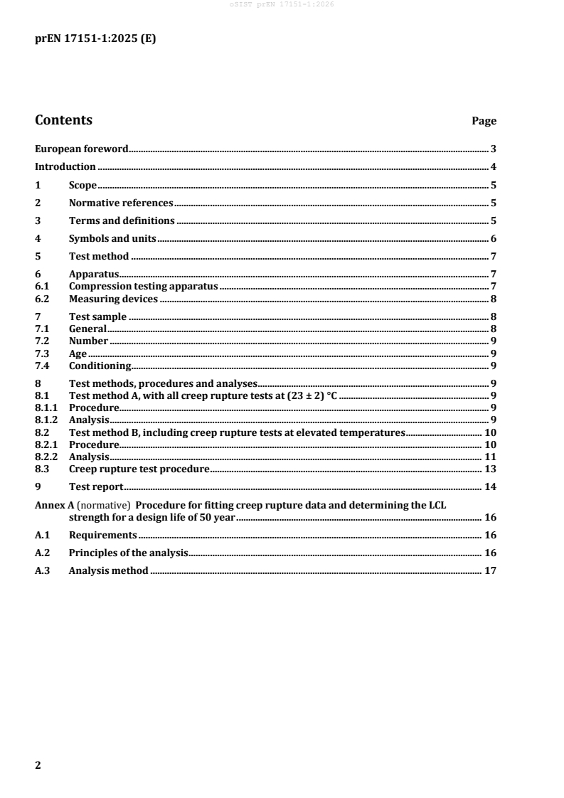
Contents Page
European foreword . 3
Introduction . 4
1 Scope . 5
2 Normative references . 5
3 Terms and definitions . 5
4 Symbols and units . 6
5 Test method . 7
6 Apparatus . 7
6.1 Compression testing apparatus . 7
6.2 Measuring devices . 8
7 Test sample . 8
7.1 General . 8
7.2 Number . 9
7.3 Age . 9
7.4 Conditioning . 9
8 Test methods, procedures and analyses . 9
8.1 Test method A, with all creep rupture tests at (23 ± 2) °C . 9
8.1.1 Procedure. 9
8.1.2 Analysis . 9
8.2 Test method B, including creep rupture tests at elevated temperatures . 10
8.2.1 Procedure. 10
8.2.2 Analysis . 11
8.3 Creep rupture test procedure . 13
9 Test report . 14
Annex A (normative) Procedure for fitting creep rupture data and determining the LCL
strength for a design life of 50 year . 16
A.1 Requirements . 16
A.2 Principles of the analysis . 16
A.3 Analysis method . 17
oSIST prEN 17151-1:2026
prEN 17151-1:2025 (E)
European foreword
This document (prEN 17151-1:2025) has been prepared by Technical Committee CEN/TC 155 “Plastics
piping systems and ducting systems”, the secretariat of which is held by NEN.
This document is currently submitted to the CEN Enquiry.
This document will supersede EN 17151:2019.
This document includes the following significant changes with respect to EN 17151:2019:
— test procedure 23 °C improved (8.1);
— test method including creep rupture tests at elevated temperatures (8.2);
— linear fit data set better defined with requirement r ;
— Annex A of EN 17151:2019 deleted;
— the number of the document is changed in part 1.
prEN 17151 consists of the following parts under the general title Plastics piping systems for non-pressure
underground conveyance and storage of surface water:
— Part 1: Test method for determination of long-term compression strength of boxes
— Part 2: Test method for determination of creep behaviour of boxes
oSIST prEN 17151-1:2026
prEN 17151-1:2025 (E)
Introduction
This document is intended to reflect the current state of knowledge of determining and predicting the
long-term lifetime of products mentioned in the scope while maintaining reasonable testing times for
producers and developers of these systems.
The products covered by this document are part of surface water management systems.
CEN/TC 155 is aware that these products are used in modular systems and that the long-term
compression strength determined by this document applies to a single box and might not reflect the
maximum allowable loads on an installed system.
The test method follows the principles of ISO 9080 [1] and applies them to the testing of boxes.
Linearity is assumed to extrapolate the stress vs. log(time) or log(stress) vs. log(time) curve from the
results of the creep rupture tests.
oSIST prEN 17151-1:2026
prEN 17151-1:2025 (E)
1 Scope
This document specifies a test method for determining the long-term compression strength for a
specified period on boxes made of thermoplastics materials for non-pressure underground conveyance
and storage of surface water.
The test method is applicable for boxes that fail due to creep rupture when subjected to a constant applied
stress and where the relationship of stress or log(stress) vs. log (failure time) is linear and of constant
gradient over the entire specified period with a coefficient of determination greater than 0,8.
The test method in this document allows extrapolation of stress or log(stress) vs. log(failure time) of up
to two decades in time and also specifies a method of accelerated testing using time-temperature
superposition of stress or log(stress) vs. log(failure time) to enable a more rapid determination that a
box obeys a constant gradient linear relationship of stress or log(stress) vs. log(failure time) over the
entire specified period.
2 Normative references
The following documents are referred to in the text in such a way that some or all of their content
constitutes requirements of this document. For dated references, only the edition cited applies. For
undated references, the latest edition of the referenced document (including any amendments) applies.
EN ISO 7500-1:2018, Metallic materials — Calibration and verification of static uniaxial testing machines
— Part 1: Tension/compression testing machines — Calibration and verification of the force-measuring
system (ISO 7500-1:2018)
3 Terms and definitions
For the purposes of this document, the following terms and definitions apply.
ISO and IEC maintain terminological databases for use in standardization at the following addresses:
— IEC Electropedia: available at https://www.electropedia.org/
— ISO Online browsing platform: available at https://www.iso.org/obp
3.1
box
thermoplastic cuboid shaped element, with or without sidewalls, used to create a modular storage system
3.2
integral component
load bearing component contributing to the overall strength of the box
3.3
initial height, length, width
h , l , b
i i i
respectively height (test direction), length and width of the sample before testing, in mm
3.4
initial height after pre-load
h
height of the sample after applying a pre-load, but before the load is further increased and recorded, in
mm
oSIST prEN 17151-1:2026
prEN 17151-1:2025 (E)
3.5
long-term compression strength
σ
r
95 % lower confidence limit of the applied stress for which the sample would survive 50 years without
creep rupture, in kN/m
3.6
linear behaviour
products that exhibit linear behaviour are defined as those that exhibit a linear relationship of stress vs.
log(time) or log(stress) vs. log (failure time) throughout the recorded and extrapolated lifetime
3.7
test duration periods (TDP1, TDP2, TDP3, TDP4)
specifies the duration of a series of creep rupture tests failing in a specific period of time
4 Symbols and units
For the purposes of this document, the following symbols and units apply.
Units
h initial height mm
i
l initial length mm
i
b initial width mm
i
h initial height after pre-load mm
σ failure stress, long-term kN/m
fl
σ failure stress, short-term kN/m
fs
σmax short-term compression strength kN/m
σ long-term compression strength kN/m
r
t time when the test load is applied h
t failure time, short-term h
fl
t failure time, long-term h
fs
a, b constants for fitting a straight line -
y, x variables for fitting a straight line -
t time h
σ applied stress kN/m
T reference temperature °C
T1, …, Ti elevated test temperatures °C
log α , …, log α shift factors -
1 i
σ , …, σ average stresses kN/m
1 average i average
oSIST prEN 17151-1:2026
prEN 17151-1:2025 (E)
a , a , …, a y-intercepts -
0 1 i
b , b , …, b gradients -
0 1 i
s , s , …, s standard errors -
b0 b1 bi
2 2 2 2
r , r , r , …, r coefficients of determination -
1 2 i
y , x data pair for fitting a straight line number i -
i i
t , σ data pair of time and stress number i -
i i
N number of data pairs -
u(a), u(b) the standard uncertainties in the fit -
intercept, u(a), the fit gradient, u(b)
5 Test method
Creep rupture tests are performed at different load levels, either at 23 °C (method A – see 8.1) or at 23 °C
and elevated temperatures (method B – see 8.2).
The load levels and for method B the temperatures are selected to distribute the failures evenly over log-
(time).
The creep rupture tests are carried out by testing a series of samples placed between two stiff plates with
different constant compression loads applied at a constant temperature. Deflection is recorded against
time. The different times taken for creep rupture to occur are used to plot a trend line which, when
extrapolated, can be used to predict the stress at which creep rupture will occur at a specific time in the
future. The uncertainty of the extrapolated value is determined to enable the definition of a lower limit
at a specified confidence level.
NOTE Creep rupture tests give information on a change of strain at failure with failure time.
6 Apparatus
6.1 Compression testing apparatus
The testing apparatus shall be capable of applying a constant load via stiff plates. The load may be applied
either directly or indirectly, e.g. by use of a lever arm arrangement. The load shall be applied
perpendicular (90° ± 1°) to the bottom plate.
Where the compression load can be applied to the test sample, the plates shall be flat, smooth and clean
and shall not deform during the test to an extent that would affect the results. The out of plane
deformation of the plates shall be less than 1,0 mm for the loads applied. The upper plate shall be fixed
(plate type 1) or shall have the capability to rotate around one or both horizontal axes (plate type 2). If a
test sample has integral protrusions, it is allowed to use an additional loose flat plate with recesses as a
load distribution layer to secure acceptable contact between the surface of the test sample and the plate
of the testing machine or remove the integral protrusions.
The length and the width of each plate shall be greater than the length and width of the test sample.
If the force is applied by a force multiplication device, the resultant load applied to the sample shall be
validated using an appropriate load cell that has been calibrated according to EN ISO 7500-1:2018, class
2.
oSIST prEN 17151-1:2026
prEN 17151-1:2025 (E)
6.2 Measuring devices
Timing devices shall be capable of continuously measuring the testing time with an accuracy of 1 min or
less.
Dimensional measuring devices shall be capable of determining the test piece dimensions with an
accuracy of 1 mm or less.
Displacement measuring devices shall be capable of continuously measuring and recording the distance
between the two plates of the compression machine with an accuracy of 0,1 mm or less.
Weighing devices shall be capable of measuring the weight of the test sample, with an accuracy better
than 0,1 % of the sample weight. They shall be capable of measuring the weight of the plate(s) and the
dead load, if applicable, with an accuracy better than 0,5 % of the weight of the plates or dead load.
Load measuring device shall be capable of continuously measuring and recording the magnitude of the
compression load being applied onto the sample with an accuracy according to EN ISO 7500-1:2018 class
2 or better.
Where dead loads are used that do not change their weight throughout the period of the test, no
continuous measuring and recording of the compression load being applied is required. However, the
resultant load applied to the sample using a dead load shall be validated before and after the test using
an appropriate load cell that has been calibrated according to EN ISO 7500-1:2018 to be class 2 or better.
If the difference is greater than the allowed variation, in 8.3, the data shall be discarded.
NOTE Porous/ hygroscopic dead weights, e.g. concrete, can change weight due to age and environmental
conditions, especially humidity.
Temperature measuring devices, capable of continuously measuring and recording the temperature of
the environment around the sample with an accuracy of 0,1 °C.
7 Test sample
7.1 General
The test sample shall consist of a box with integral components which represent the weakest entity of the
final construction.
Figure 1 — Identification of the test direction of the box
In Figure 1, the Z-direction is the preferred vertical direction of installation.
Those which are homogeneous extruded boxes shall be cut to obtain a test sample representative of the
structure of the box and shall furthermore be cut with a minimum length of 0,5 m in the Z-direction. The
ratio between the X-direction and Z-direction, and Y-direction and the Z-direction shall be less than 1,0.
Identification of the test direction can be found in Figure 1.
oSIST prEN 17151-1:2026
prEN 17151-1:2025 (E)
7.2 Number
The number of test samples shall be one per test, if not otherwise specified in the referring standard.
7.3 Age
At the start of testing in accordance with Clause 8, the age of the test samples shall be at least 21 days.
7.4 Conditioning
The test samples shall be conditioned in air at test temperature for at least 24 h immediately prior to
testing in accordance with Clause 8.
8 Test methods, procedures and analyses
8.1 Test method A, with all creep rupture tests at (23 ± 2) °C
8.1.1 Procedure
Unless otherwise specified in the referring standard, carry out the following procedure at a test
temperatu
...