

ASTM D7498/D7498M-09(2022)
(Test Method)Standard Test Method for Vertical Strip Drains Using a Large-Scale Consolidation Test
General Information
- Abstract
SIGNIFICANCE AND USE
5.1 As this is a time-intensive test, it should not be considered as an acceptance test for commercial shipments of prefabricated vertical strip drains.
5.2 Prior to the development of vertical strip drains, when it was desired to increase the rate of consolidation of a compressible soil on a construction project, large-diameter sand drains were installed. Vertical strip drains can be installed in areas where it is desired to increase the rate of soils consolidation in place of these large-diameter sand drains.
5.3 This test method can be used to compare the performance of vertical strip drains to that of sand drains.
SCOPE
1.1 This test method is a performance test which measures the effectiveness of vertical strip drains on the time rates of consolidation of compressible soils from construction project sites.
1.1.1 It is expected that the design agency will be responsible for performing this test. It is not intended to be a manufacturer-performed test.
1.2 This test method is applicable to all vertical strip drains.
1.3 The values stated in either SI units or inch-pound units are to be regarded separately as standard. The values stated in each system are not necessarily exact equivalents; therefore, to ensure conformance with the standard, each system shall be used independently of the other, and values from the two systems shall not be combined.
1.4 This standard does not purport to address all of the safety concerns, if any, associated with its use. It is the responsibility of the user of this standard to establish appropriate safety, health, and environmental practices and determine the applicability of regulatory limitations prior to use.
1.5 This international standard was developed in accordance with internationally recognized principles on standardization established in the Decision on Principles for the Development of International Standards, Guides and Recommendations issued by the World Trade Organization Technical Barriers to Trade (TBT) Committee.
- Status
- Published
- Publication Date
- 30-Apr-2022
- Technical Committee
- D35 - Geosynthetics
- Drafting Committee
- D35.03 - Permeability and Filtration
Overview
ASTM D7498/D7498M-09(2022), titled Standard Test Method for Vertical Strip Drains Using a Large-Scale Consolidation Test, presents a performance test to evaluate the effectiveness of vertical strip drains in accelerating the consolidation of compressible soils. Developed by ASTM International, this standard plays a crucial role for geotechnical engineers and design agencies involved in large-scale construction and infrastructure projects where ground improvement and soil stability are critical.
Vertical strip drains, also known as prefabricated vertical drains (PVDs), have increasingly replaced traditional large-diameter sand drains due to their ease of installation and performance in various soil improvement applications. ASTM D7498/D7498M outlines procedures for comparing the consolidation performance of these vertical strip drains to that of sand drains using a large-scale laboratory test.
Key Topics
Purpose and Applicability
- Measures the effectiveness of vertical strip drains in accelerating soil consolidation.
- Suitable for all types of vertical strip drains, but not designed as a manufacturer acceptance test.
Test Responsibility
- Intended for use by design agencies, not manufacturers or for commercial shipment acceptance.
Test Method Essentials
- Utilizes a large-scale consolidation test chamber filled with compressible project soil.
- Direct comparison between vertical strip drains and sand drains under controlled loading conditions.
- Involves remolding and placement of soil, sealing to ensure drainage occurs only through the installed strip drain, and application of incremental loads to simulate in-situ conditions.
Performance Metrics
- Coefficient of consolidation and time rate of consolidation are determined for both vertical strip and sand drains.
- Results help inform field spacing requirements and ground improvement design decisions.
Standardization and Units
- Values may be stated in either SI or inch-pound units, but systems are not to be mixed.
User Safety and Compliance
- Users are responsible for following proper safety, health, and environmental protocols as the standard does not cover site-specific risks.
Applications
ASTM D7498/D7498M-09(2022) is widely applied in:
Geotechnical Site Investigations
- Assists design agencies in evaluating how vertical strip drains can be used to accelerate consolidation in soft, compressible soils-reducing settlement timeframes for embankments, roadways, or structures.
Ground Improvement Works
- Supports decision-making for the replacement or supplementation of sand drains with prefabricated vertical strip drains in new or existing projects.
Comparative Performance Assessment
- Enables an objective, laboratory-based comparison between different vertical strip drain products and the more traditional sand drain solutions.
Infrastructure, Highway, and Rail Projects
- Facilitates the specification and optimization of drain systems for transportation corridors or other structures requiring enhanced soil consolidation.
Related Standards
For users of ASTM D7498/D7498M-09(2022), the following standards provide further guidance and definitions:
- ASTM D4354 - Practice for Sampling of Geosynthetics and Rolled Erosion Control Products (RECPs) for Testing
- ASTM D4439 - Terminology for Geosynthetics
These documents offer important context for the laboratory sampling, test specimen preparation, and terminology related to geosynthetics used in soil improvement and ground engineering.
Keywords: ASTM D7498, vertical strip drains, consolidation test, soil improvement, geotechnical standards, prefabricated vertical drains, ground improvement, sand drains, large-scale consolidation, coefficient of consolidation, geosynthetics.
Relations
- Effective Date
- 01-Feb-2024
- Effective Date
- 01-May-2020
- Effective Date
- 15-Apr-2018
- Effective Date
- 01-Aug-2017
- Effective Date
- 01-Sep-2015
- Effective Date
- 01-Jul-2015
- Effective Date
- 01-Mar-2014
- Effective Date
- 01-Jul-2012
- Effective Date
- 01-Oct-2011
- Effective Date
- 15-Jan-2009
- Effective Date
- 01-Nov-2004
- Effective Date
- 01-Jun-2004
- Effective Date
- 10-Aug-2002
- Effective Date
- 10-Sep-2001
- Effective Date
- 10-Sep-2001
Get Certified
Connect with accredited certification bodies for this standard

Zavod za gradbeništvo Slovenije (ZAG) - Inšpekcija
ZAG inspection body for construction products, structures, and materials.
Sponsored listings
Frequently Asked Questions
ASTM D7498/D7498M-09(2022) is a standard published by ASTM International. Its full title is "Standard Test Method for Vertical Strip Drains Using a Large-Scale Consolidation Test". This standard covers: SIGNIFICANCE AND USE 5.1 As this is a time-intensive test, it should not be considered as an acceptance test for commercial shipments of prefabricated vertical strip drains. 5.2 Prior to the development of vertical strip drains, when it was desired to increase the rate of consolidation of a compressible soil on a construction project, large-diameter sand drains were installed. Vertical strip drains can be installed in areas where it is desired to increase the rate of soils consolidation in place of these large-diameter sand drains. 5.3 This test method can be used to compare the performance of vertical strip drains to that of sand drains. SCOPE 1.1 This test method is a performance test which measures the effectiveness of vertical strip drains on the time rates of consolidation of compressible soils from construction project sites. 1.1.1 It is expected that the design agency will be responsible for performing this test. It is not intended to be a manufacturer-performed test. 1.2 This test method is applicable to all vertical strip drains. 1.3 The values stated in either SI units or inch-pound units are to be regarded separately as standard. The values stated in each system are not necessarily exact equivalents; therefore, to ensure conformance with the standard, each system shall be used independently of the other, and values from the two systems shall not be combined. 1.4 This standard does not purport to address all of the safety concerns, if any, associated with its use. It is the responsibility of the user of this standard to establish appropriate safety, health, and environmental practices and determine the applicability of regulatory limitations prior to use. 1.5 This international standard was developed in accordance with internationally recognized principles on standardization established in the Decision on Principles for the Development of International Standards, Guides and Recommendations issued by the World Trade Organization Technical Barriers to Trade (TBT) Committee.
SIGNIFICANCE AND USE 5.1 As this is a time-intensive test, it should not be considered as an acceptance test for commercial shipments of prefabricated vertical strip drains. 5.2 Prior to the development of vertical strip drains, when it was desired to increase the rate of consolidation of a compressible soil on a construction project, large-diameter sand drains were installed. Vertical strip drains can be installed in areas where it is desired to increase the rate of soils consolidation in place of these large-diameter sand drains. 5.3 This test method can be used to compare the performance of vertical strip drains to that of sand drains. SCOPE 1.1 This test method is a performance test which measures the effectiveness of vertical strip drains on the time rates of consolidation of compressible soils from construction project sites. 1.1.1 It is expected that the design agency will be responsible for performing this test. It is not intended to be a manufacturer-performed test. 1.2 This test method is applicable to all vertical strip drains. 1.3 The values stated in either SI units or inch-pound units are to be regarded separately as standard. The values stated in each system are not necessarily exact equivalents; therefore, to ensure conformance with the standard, each system shall be used independently of the other, and values from the two systems shall not be combined. 1.4 This standard does not purport to address all of the safety concerns, if any, associated with its use. It is the responsibility of the user of this standard to establish appropriate safety, health, and environmental practices and determine the applicability of regulatory limitations prior to use. 1.5 This international standard was developed in accordance with internationally recognized principles on standardization established in the Decision on Principles for the Development of International Standards, Guides and Recommendations issued by the World Trade Organization Technical Barriers to Trade (TBT) Committee.
ASTM D7498/D7498M-09(2022) is classified under the following ICS (International Classification for Standards) categories: 93.030 - External sewage systems. The ICS classification helps identify the subject area and facilitates finding related standards.
ASTM D7498/D7498M-09(2022) has the following relationships with other standards: It is inter standard links to ASTM D4439-24, ASTM D4354-12(2020), ASTM D4439-18, ASTM D4439-17, ASTM D4439-15a, ASTM D4439-15, ASTM D4439-14, ASTM D4354-12, ASTM D4439-11, ASTM D4354-99(2009), ASTM D4354-99(2004), ASTM D4439-04, ASTM D4439-02, ASTM D4439-00, ASTM D4439-01. Understanding these relationships helps ensure you are using the most current and applicable version of the standard.
ASTM D7498/D7498M-09(2022) is available in PDF format for immediate download after purchase. The document can be added to your cart and obtained through the secure checkout process. Digital delivery ensures instant access to the complete standard document.
Standards Content (Sample)
This international standard was developed in accordance with internationally recognized principles on standardization established in the Decision on Principles for the
Development of International Standards, Guides and Recommendations issued by the World Trade Organization Technical Barriers to Trade (TBT) Committee.
Designation: D7498/D7498M − 09 (Reapproved 2022)
Standard Test Method for
Vertical Strip Drains Using a Large-Scale Consolidation
Test
This standard is issued under the fixed designation D7498/D7498M; the number immediately following the designation indicates the
year of original adoption or, in the case of revision, the year of last revision. A number in parentheses indicates the year of last
reapproval. A superscript epsilon (´) indicates an editorial change since the last revision or reapproval.
1. Scope 3. Terminology
1.1 This test method is a performance test which measures 3.1 Definitions—Fordefinitionsrelatedtogeosynthetics,see
the effectiveness of vertical strip drains on the time rates of Terminology D4439.
consolidation of compressible soils from construction project
3.2 Definitions of Terms Specific to This Standard:
sites.
3.2.1 vertical strip drains, n—a geocomposite consisting of
1.1.1 It is expected that the design agency will be respon-
a geotextile cover and drainage core installed vertically into
sible for performing this test. It is not intended to be a
soil to provide drainage for accelerated consolidation of soils.
manufacturer-performed test.
4. Summary of Test Method
1.2 This test method is applicable to all vertical strip drains.
4.1 This test method describes procedures for determining
1.3 The values stated in either SI units or inch-pound units
the effectiveness of vertical strip drains used under specified
are to be regarded separately as standard. The values stated in
soil conditions to enhance the time rate of consolidation of
each system are not necessarily exact equivalents; therefore, to
compressible soils.
ensure conformance with the standard, each system shall be
4.2 A specimen of the vertical strip drain is inserted in the
used independently of the other, and values from the two
test chamber and compressible soil from the project site is
systems shall not be combined.
remolded around the vertical strip drain, such that the drain is
1.4 This standard does not purport to address all of the
in a similar position as it would be on the project site.
safety concerns, if any, associated with its use. It is the
4.3 The top of the soil is sealed with a wax seal, such that
responsibility of the user of this standard to establish appro-
drainage only occurs through the vertical strip drain. The
priate safety, health, and environmental practices and deter-
vertical strip drain protrudes up through the seal.
mine the applicability of regulatory limitations prior to use.
1.5 This international standard was developed in accor-
4.4 Asanddrainageblanketisplacedontopofthewaxseal,
dance with internationally recognized principles on standard-
such that the vertical strip drain drains into the sand blanket.
ization established in the Decision on Principles for the
4.5 A rubber cup seal provides the means of applying
Development of International Standards, Guides and Recom-
incremental loads in a similar manner to a standard soils
mendations issued by the World Trade Organization Technical
consolidation test.
Barriers to Trade (TBT) Committee.
4.6 A similar setup is used, only with a 50 mm [2 in.] sand
2. Referenced Documents
drain in place of the vertical strip drain.
2.1 ASTM Standards:
4.7 The coefficients of consolidation are determined from
D4354 Practice for Sampling of Geosynthetics and Rolled the test results for both the vertical strip drain and the sand
Erosion Control Products (RECPs) for Testing
drain. Time rates of consolidation are then compared.
D4439 Terminology for Geosynthetics
4.8 Persons performing this test shall have knowledge in the
consolidation testing of soils.
This test method is under the jurisdiction of ASTM Committee D35 on
5. Significance and Use
Geosynthetics and is the direct responsibility of Subcommittee D35.03 on Perme-
ability and Filtration.
5.1 As this is a time-intensive test, it should not be consid-
Current edition approved May 1, 2022. Published May 2022. Originally
ered as an acceptance test for commercial shipments of
approved in 2009. Last previous edition approved in 2014 as D7498/D7498M – 09
ɛ1
prefabricated vertical strip drains.
(2014) . DOI: 10.1520/D7498_D7498M-09R22.
For referenced ASTM standards, visit the ASTM website, www.astm.org, or
5.2 Prior to the development of vertical strip drains, when it
contact ASTM Customer Service at service@astm.org. For Annual Book of ASTM
was desired to increase the rate of consolidation of a compress-
Standards volume information, refer to the standard’s Document Summary page on
the ASTM website. ible soil on a construction project, large-diameter sand drains
Copyright © ASTM International, 100 Barr Harbor Drive, PO Box C700, West Conshohocken, PA 19428-2959. United States
D7498/D7498M − 09 (2022)
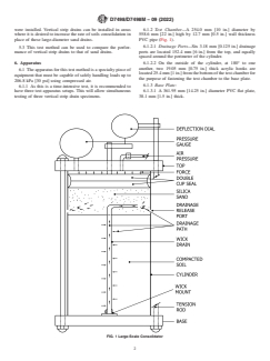
were installed. Vertical strip drains can be installed in areas 6.1.2 Test Chamber—A 254.0 mm [10 in.] diameter by
where it is desired to increase the rate of soils consolidation in 558.6 mm [22 in.] high by 12.7 mm [0.5 in.] wall thickness
place of these large-diameter sand drains. PVC pipe (Fig. 1).
6.1.2.1 Drainage Ports—Six 3.18 mm [0.125 in.] drainage
5.3 This test method can be used to compare the perfor-
ports are located 152.4 mm [6 in.] from the top, and equally
mance of vertical strip drains to that of sand drains.
spaced around the perimeter of the cylinder.
6. Apparatus 6.1.2.2 On the outside of the cylinder, at 180° to one
another, two 19.05 mm [0.75 in.] thick acrylic hooks are
6.1 The apparatus for this test method is a specialty piece of
located25.4mm[1in.]fromthebottomofthetestchamberfor
equipment that must be capable of safely handling loads up to
the purpose of fastening the test chamber to the base plate.
206.8 kPa [30 psi] using compressed air.
6.1.3 Base Plate:
6.1.1 As this is a time-intensive test, it is recommended to
have three test apparatus setups. This will allow simultaneous 6.1.3.1 A 361.95 mm [14.25 in.] diameter PVC flat plate,
testing of three vertical strip drain specimens. 38.1 mm [1.5 in.] thick.
FIG. 1 Large-Scale Consolidator
D7498/D7498M − 09 (2022)
6.1.3.2 The base plate has a 12.7 mm [0.5 in.] wide by 7. Materials
6.35 mm [0.25 in.] deep concentric groove, having an inside
7.1 Project Soil—A quantity of in-situ compressible soil
diameter of 254.0 mm [10 in.], located on the top side of the
large enough to perform the number of required tests shall be
base plate.
obtained from the project site. This does not have to be
6.1.3.3 A3.17 mm [0.125 in.] by 228.6 mm [9 in.] diameter
undisturbed soil.
rubber O-ring is stretched and placed in this groove.
NOTE 2—The quantity of soil needed shall be figured based on filling
6.1.3.4 The test chamber is seated into the groove on top of
the test chamber to a height of 381 mm [15 in.] at the desired density.
the O-ring.
7.2 Silicone Spray—The spray is used to lubricate the inside
6.1.4 Tension Rods:
surface of the test chamber to minimize friction between the
6.1.4.1 Equally spaced around the base plate, 158.75 mm
soil and the chamber surface.
[6.25 in.] from the center of the plate, are six 0.952 mm
[0.375 in.] diameter by 76.2 mm [30 in.] long threaded tension
8. Hazards
rods.
8.1 There are no known hazards with the materials or in
6.1.4.2 Each tension rod is attached to the base plate by two
performing the test.
hex nuts, one above the plate and one beneath.
6.1.4.3 On two 180° opposing tension rods place a wing nut
9. Sampling, Laboratory Samples, and Test Specimens
that is used to secure the test chamber to the base plate via the
hooks referred to in 6.1.2.2.
9.1 LotSample—Asalotsampleforacceptancetesting,take
the number of units as directed in Table 3 in Practice D4354.
6.1.5 Double Cup Seal Assembly:
Consider rolls of the vertical strip drain to be the primary
6.1.5.1 This is used to evenly distribute the consolidation
sampling units.
load over the soil in the test chamber. It consists of the
following parts:
9.2 Laboratory Sample—Take for the laboratory sample a
6.1.5.2 Two 254.00 mm [10 in.] diameter by 4.76 mm
sample 1829 mm [72 in.] in length from each of the lot
[0.3125 in.] thick rubber cup seals that are placed back to back.
samples.Beforetakingthelaboratorysample,removetheouter
Theyaresandwichedbetweentwo241.3mm[9.5in.]diameter
layer of drain from the sample roll to avoid testing any
by 12.7 mm [0.5 in.] flat PVC plates.
damaged material.
6.1.5.3 A 12.7 mm [0.5 in.] diameter by 228.6 mm [9 in.]
9.3 Test Specimens—From each laboratory sample cut three
long center rod centrally located on the cup seal assembly. It is
test specimens, each 508.0 mm [20 in.] long, making sure each
attached to the assembly by a ball-and-socket device.
end of the specimen is cut square.
6.1.5.4 A removable PVC platform that is attached to the
9.3.1 At one end of each test specimen cut three notches
center rod after the test chamber is completely assembled.This
6.35 mm [0.25 in.] by 12.7 mm [0.5 in.] long. Each notch
is used to seat the deflection dial or transducer on.
should line up with the mounting bolts in the specimen mount.
6.1.6 Top Plate:
See Fig. 1.
6.1.6.1 An identical plate to the base plate, including the 9.3.2 Place a 25.4 mm [1 in.] wide piece of masking tape
groove for test chamber seating, and holes for tension rods to aroundeachtestspecimen,coveringtheareafrom374.6mmto
go through. 400.0 mm [14.75 to 15.74 in.] of the length of each specimen.
6.1.6.2 A3.17 mm [0.125 in.] by 228.6 mm [9 in.] diameter
10. Test Setup
rubber O-ring is stretched and placed in the groove.
6.1.6.3 A threaded 6.35 mm [0.25 in.] diameter hole going
10.1 Compute the total wet mass of soil to be used in each
completely through the top plate into which a brass fitting is
chamber by multiplying the desired wet density by the volume
mounted. The air supply line is attached to this fitting. The
the soil will occupy. This is the initial mass of soil.
consolidation loads are applied through this air line.
10.2 Taking a small portion of the wet soil from 10.1,
6.1.6.4 The double cup seal assembly is mounted through a
determine and record the initial moisture content of the soil to
holeinthecenterofthetopplate.Thecupsealsareplacedsuch
be placed in the test chamber using Eq 1:
that they will be inside the test chamber.
w 5 @~W 2 W !/W# 3100 % (1)
i T S
6.1.6.5 Apressure gauge for reading the applied air pressure
is mounted to the top plate such that it reads the pressure inside
where:
the test chamber.
w = initial moisture content (%),
i
6.1.7 Adeflection dial or electronic displacement transducer
W = total wet mass of soil (g), and
T
graduated in 0.0254 mm [0.001 in.] divisions.
W = dry mass of soil (g).
S
6.1.7.1 The deflection measuring device is attached to the
10.3 Secure the test chamber to the bottom base, making
top plate by mounting it on a rod mounted to the outer edge of
sure that the O-ring seal is in place in the base plate.
the top plate.
10.4 Draw a line around the inside of the test chamber
6.1.8 Vertical Strip Drain Mount—Aflat PVC plate cut to fit
381.0 mm [15 in.] up from the top surface of the base plate.
the inside of the test chamber.
This is the height to which the soil will be placed, and is the
NOTE1—SeeFigs.1and2forschematicdiagramsofthetestapparatus. initial height of soil in the test ch
...