

prEN 15194
(Main)Cycles - Electrically power assisted cycles - EPAC Bicycles
- Abstract
This European Standard applies to EPAC bicycles for private and commercial use with exception of EPAC intended for hire from unattended station.
This European Standard is intended to cover all common significant hazards, hazardous situations and events (see Clause 4) of electrically power assisted bicycles, when used as intended and under condition of misuse that are reasonably foreseeable by the manufacturer.
This European Standard is intended to cover electrically power assisted bicycles of a type which have a maximum continuous rated power of 0,25 kW, of which the output is progressively reduced and finally cut off as the EPAC reaches a speed of 25 km/h, or sooner, if the cyclist stops pedalling.
This European Standard specifies requirements and test methods for engine power management systems, electrical circuits including the charging system for the design and assembly of electrically power assisted bicycles and sub-assemblies for systems having a rated voltage up to and including 48 V d.c. or integrated battery charger with a nominal 230 V a.c. input.
This European Standard specifies safety and safety related performance requirements for the design, assembly, and testing of EPAC bicycles and subassemblies intended for use on public roads, and lays down guidelines for instructions on the use and care of such bicycles.
This European Standard applies to EPAC bicycles that have a maximum saddle height of 635 mm or more and that are intended for use on public roads.
This European Standard is not applicable to EPACs which are manufactured before the date of its publication as EN.
- Status
- Not Published
- Publication Date
- 25-Apr-2027
- Technical Committee
- CEN/TC 333 - Cycles
- Drafting Committee
- CEN/TC 333/WG 5 - Electric power assisted cycles
- Current Stage
- 4020 - Submission to enquiry - Enquiry
- Start Date
- 22-Oct-2026
- Due Date
- 02-Jan-2026
- Completion Date
- 22-Oct-2026

Relations
- Effective Date
- 12-Feb-2025
Get Certified
Connect with accredited certification bodies for this standard

TÜV Rheinland
TÜV Rheinland is a leading international provider of technical services.

TÜV SÜD
TÜV SÜD is a trusted partner of choice for safety, security and sustainability solutions.

DEKRA Certification Inc.
DEKRA US certification services.
Sponsored listings
Frequently Asked Questions
prEN 15194 is a draft published by the European Committee for Standardization (CEN). Its full title is "Cycles - Electrically power assisted cycles - EPAC Bicycles". This standard covers: This European Standard applies to EPAC bicycles for private and commercial use with exception of EPAC intended for hire from unattended station. This European Standard is intended to cover all common significant hazards, hazardous situations and events (see Clause 4) of electrically power assisted bicycles, when used as intended and under condition of misuse that are reasonably foreseeable by the manufacturer. This European Standard is intended to cover electrically power assisted bicycles of a type which have a maximum continuous rated power of 0,25 kW, of which the output is progressively reduced and finally cut off as the EPAC reaches a speed of 25 km/h, or sooner, if the cyclist stops pedalling. This European Standard specifies requirements and test methods for engine power management systems, electrical circuits including the charging system for the design and assembly of electrically power assisted bicycles and sub-assemblies for systems having a rated voltage up to and including 48 V d.c. or integrated battery charger with a nominal 230 V a.c. input. This European Standard specifies safety and safety related performance requirements for the design, assembly, and testing of EPAC bicycles and subassemblies intended for use on public roads, and lays down guidelines for instructions on the use and care of such bicycles. This European Standard applies to EPAC bicycles that have a maximum saddle height of 635 mm or more and that are intended for use on public roads. This European Standard is not applicable to EPACs which are manufactured before the date of its publication as EN.
This European Standard applies to EPAC bicycles for private and commercial use with exception of EPAC intended for hire from unattended station. This European Standard is intended to cover all common significant hazards, hazardous situations and events (see Clause 4) of electrically power assisted bicycles, when used as intended and under condition of misuse that are reasonably foreseeable by the manufacturer. This European Standard is intended to cover electrically power assisted bicycles of a type which have a maximum continuous rated power of 0,25 kW, of which the output is progressively reduced and finally cut off as the EPAC reaches a speed of 25 km/h, or sooner, if the cyclist stops pedalling. This European Standard specifies requirements and test methods for engine power management systems, electrical circuits including the charging system for the design and assembly of electrically power assisted bicycles and sub-assemblies for systems having a rated voltage up to and including 48 V d.c. or integrated battery charger with a nominal 230 V a.c. input. This European Standard specifies safety and safety related performance requirements for the design, assembly, and testing of EPAC bicycles and subassemblies intended for use on public roads, and lays down guidelines for instructions on the use and care of such bicycles. This European Standard applies to EPAC bicycles that have a maximum saddle height of 635 mm or more and that are intended for use on public roads. This European Standard is not applicable to EPACs which are manufactured before the date of its publication as EN.
prEN 15194 is classified under the following ICS (International Classification for Standards) categories: 43.120 - Electric road vehicles. The ICS classification helps identify the subject area and facilitates finding related standards.
prEN 15194 has the following relationships with other standards: It is inter standard links to EN 15194:2017+A1:2023. Understanding these relationships helps ensure you are using the most current and applicable version of the standard.
prEN 15194 is associated with the following European legislation: EU Directives/Regulations: 2023/1230; Standardization Mandates: M/605. When a standard is cited in the Official Journal of the European Union, products manufactured in conformity with it benefit from a presumption of conformity with the essential requirements of the corresponding EU directive or regulation.
prEN 15194 is available in PDF format for immediate download after purchase. The document can be added to your cart and obtained through the secure checkout process. Digital delivery ensures instant access to the complete standard document.
Standards Content (Sample)
SLOVENSKI STANDARD
01-december-2026
Kolesa - Kolesa z električnim pomožnim pogonom - Kolesa EPAC
Cycles - Electrically power assisted cycles - EPAC Bicycles
Fahrräder - Elektromotorisch unterstützte Räder - EPAC
Cycles - Cycles à assistance électrique - Bicyclettes EPAC
Ta slovenski standard je istoveten z: prEN 15194
ICS:
43.120 Električna cestna vozila Electric road vehicles
43.150 Kolesa Cycles
2003-01.Slovenski inštitut za standardizacijo. Razmnoževanje celote ali delov tega standarda ni dovoljeno.
DRAFT
EUROPEAN STANDARD
NORME EUROPÉENNE
EUROPÄISCHE NORM
October 2026
ICS 43.120 Will supersede EN 15194:2017+A1:2023
English Version
Cycles - Electrically power assisted cycles - EPAC Bicycles
Cycles - Cycles à assistance électrique - Bicyclettes Fahrräder - Elektromotorisch unterstützte Räder -
EPAC EPAC
This draft European Standard is submitted to CEN members for enquiry. It has been drawn up by the Technical Committee
CEN/TC 333.
If this draft becomes a European Standard, CEN members are bound to comply with the CEN/CENELEC Internal Regulations
which stipulate the conditions for giving this European Standard the status of a national standard without any alteration.
This draft European Standard was established by CEN in three official versions (English, French, German). A version in any other
language made by translation under the responsibility of a CEN member into its own language and notified to the CEN-CENELEC
Management Centre has the same status as the official versions.
CEN members are the national standards bodies of Austria, Belgium, Bulgaria, Croatia, Cyprus, Czech Republic, Denmark, Estonia,
Finland, France, Germany, Greece, Hungary, Iceland, Ireland, Italy, Latvia, Lithuania, Luxembourg, Malta, Netherlands, Norway,
Poland, Portugal, Republic of North Macedonia, Romania, Serbia, Slovakia, Slovenia, Spain, Sweden, Switzerland, Türkiye and
United Kingdom.
Recipients of this draft are invited to submit, with their comments, notification of any relevant patent rights of which they are
aware and to provide supporting documentation.
Warning : This document is not a European Standard. It is distributed for review and comments. It is subject to change without
notice and shall not be referred to as a European Standard.
EUROPEAN COMMITTEE FOR STANDARDIZATION
COMITÉ EUROPÉEN DE NORMALISATION
EUROPÄISCHES KOMITEE FÜR NORMUNG
CEN-CENELEC Management Centre: Rue de la Science 23, B-1040 Brussels
© 2026 CEN All rights of exploitation in any form and by any means reserved Ref. No. prEN 15194:2026 E
worldwide for CEN national Members.
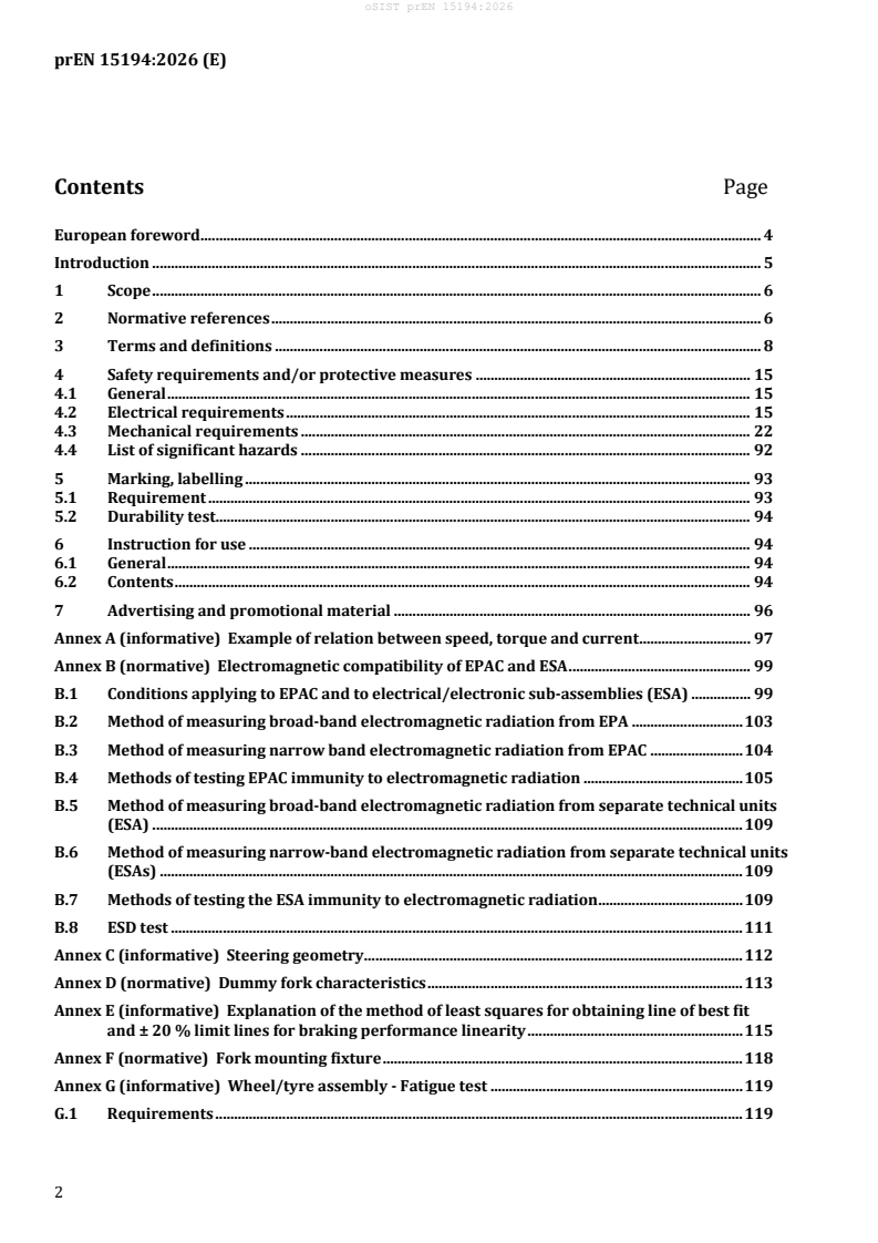
Contents Page
European foreword . 4
Introduction . 5
1 Scope . 6
2 Normative references . 6
3 Terms and definitions . 8
4 Safety requirements and/or protective measures . 15
4.1 General . 15
4.2 Electrical requirements . 15
4.3 Mechanical requirements . 22
4.4 List of significant hazards . 92
5 Marking, labelling . 93
5.1 Requirement . 93
5.2 Durability test. 94
6 Instruction for use . 94
6.1 General . 94
6.2 Contents . 94
7 Advertising and promotional material . 96
Annex A (informative) Example of relation between speed, torque and current . 97
Annex B (normative) Electromagnetic compatibility of EPAC and ESA . 99
B.1 Conditions applying to EPAC and to electrical/electronic sub-assemblies (ESA) . 99
B.2 Method of measuring broad-band electromagnetic radiation from EPA . 103
B.3 Method of measuring narrow band electromagnetic radiation from EPAC . 104
B.4 Methods of testing EPAC immunity to electromagnetic radiation . 105
B.5 Method of measuring broad-band electromagnetic radiation from separate technical units
(ESA) . 109
B.6 Method of measuring narrow-band electromagnetic radiation from separate technical units
(ESAs) . 109
B.7 Methods of testing the ESA immunity to electromagnetic radiation . 109
B.8 ESD test . 111
Annex C (informative) Steering geometry . 112
Annex D (normative) Dummy fork characteristics . 113
Annex E (informative) Explanation of the method of least squares for obtaining line of best fit
and ± 20 % limit lines for braking performance linearity . 115
Annex F (normative) Fork mounting fixture . 118
Annex G (informative) Wheel/tyre assembly - Fatigue test . 119
G.1 Requirements . 119
G.2 Test method . 119
Annex H (normative) Light, warning device, on/off symbols . 121
Annex I (informative) Walk assist mode symbols . 122
Annex J (informative) Example EPAC cybersecurity assessment and concept . 123
J.1 General. 123
J.2 Description of the EPAC system . 123
J.3 Definition of security goals . 124
J.4 Threat analysis . 125
J.5 Proposed security controls and mitigation measures . 126
Annex K (normative) Requirements on cyber security . 131
K.1 Cybersecurity and functional safety risk assessments . 131
K.2 Secure development of firmware . 131
K.3 Up-to-date software and hardware with no publicly known exploitable vulnerabilities 131
K.4 Keep software updated . 131
K.5 Only valid firmware should be executed . 132
K.6 Secure communication to the equipment . 132
K.7 Validate safety command exchanges between subcomponents . 132
K.8 Evidence of legitimate or illegitimate intervention on the machinery . 132
K.9 Secure storage of critical data . 132
K.10 Vulnerability management . 133
K.11 Minimize attack surface . 133
K.12 List of abbreviated terms for this annex . 133
Annex L (informative) Mapping between machinery §1.1.9 and §1.2.1 and cyber requirements from
external standards . 134
Annex ZA (informative) Relationship between this European Standard and the essential
requirements of Regulation (EU) 2023/1230 aimed to be covered . 136
Bibliography . 142
European foreword
This document (prEN 15194:2026) has been prepared by Technical Committee CEN/TC 333 “Cycles”, the secre-
tariat of which is held by UNI.
This document is currently submitted to the CEN Enquiry.
This document will supersede EN 15194:2017+A1:2023.
This document includes the following significant technical changes with respect to EN 15194:2017+A1:2023:
— Clause 2 “Normative references”: adding of some references,
— Clause 4.3.22: adding of a performance level specific for safety functions,
— Clause 4.3.23: adding of a specific paragraph concerning the protection against corruption,
— Clause 4.4: adding of a significant hazard regarding cybersecurity,
— New Annex J (informative), giving an example of an EPAC cybersecurity assessment and concept,
— New Annex K (normative), detailing the specific requirements on cyber security,
— New Annex L (informative), providing a list of relevant standard reference links and machinery cybersecuri-
ty.
This document has been prepared under a standardization request addressed to CEN by the European Commis-
sion. The Standing Committee of the EFTA States subsequently approves these requests for its Member States.
For the relationship with EU Legislation, see informative Annex ZA, which is an integral part of this document.
Introduction
This document gives requirements for electrically power assisted cycles (EPAC).
This document has been developed in response to demand throughout Europe. Its aim is to provide a standard
for the assessment of electrically powered cycles of a type which are excluded from type approval by Regula-
tion (EU) No 168/2013.
Due to the limitation of the voltage to 48 V DC, there are no special requirements applicable to the EPAC in re-
gard to protection against electrical hazards.
Following the completion of a risk analysis, the focus in this standard is on EPAC as bicycles for city and trek-
king. Folding bicycles are included.
This document is a type C standard as stated in EN ISO 12100. The machinery concerned and the extent to which
hazards, hazardous situations and hazardous events covered are indicated in the scope of this document.
When provisions of this type C standard are different from those which are stated in type A or B standards, the
provisions of this type C standard take precedence over the provisions of the other standards, for machines that
have been designed and built according to the provisions of this type C standard.
In real life situation an EPAC can fall over to the side causing the battery holder to break without damage to the
battery case itself. While the standard contains a strength test for the battery an additional test is required for
the situation described. This will be considered at the next revision. The battery holder needs to withstand this
realistic and typical situation. Risk assessment carried out by the manufacturer should identify suitable
measures to deal with this situation until it can be dealt with in the standard.
1 Scope
This document applies to EPAC bicycles for private and commercial use with exception of EPAC intended for hire
from unattended station.
This document is intended to cover all common significant hazards, hazardous situations and events
(see Clause 4) of electrically power assisted bicycles, when used as intended and under condition of misuse that
are reasonably foreseeable by the manufacturer.
This document is intended to cover electrically power assisted bicycles of a type which have a maximum contin-
uous rated power of 0,25 kW, of which the output is progressively reduced and finally cut off as the EPAC reach-
es a speed of 25 km/h, or sooner, if the cyclist stops pedalling.
This document specifies requirements and test methods for engine power management systems, electrical cir-
cuits including the charging system for the design and assembly of electrically power assisted bicycles and sub-
assemblies for systems having a rated voltage up to and including 48 V DC or integrated battery charger with a
nominal 230 V AC input.
This document specifies safety and safety related performance requirements for the design, assembly, and test-
ing of EPAC bicycles and subassemblies intended for use on public roads, and lays down guidelines for instruc-
tions on the use and care of such bicycles.
This document applies to EPAC bicycles that have a maximum saddle height of 635 mm or more and that are in-
tended for use on public roads.
This document is not applicable to EPACs which are manufactured before the date of its publication as EN.
2 Normative references
The following documents are referred to in the text in such a way that some or all of their content constitutes re-
quirements of this document. For dated references, only the edition cited applies. For undated references, the
latest edition of the referenced document (including any amendments) applies.
EN 22248:1992, Packaging - Complete, filled transport packages - Vertical impact test by dropping (ISO
2248:1985)
EN 50604-1:2016,1 Secondary lithium batteries for light EV (electric vehicle) applications – Part 1: General safety
requirements and test methods
EN 55012:2007,2 Vehicles, boats and internal combustion engines — Radio disturbance characteristics — Limits
and methods of measurement for the protection of off-board receivers (CISPR 12:2007)
EN IEC 55016-1-1:2019, Specification for radio disturbance and immunity measuring apparatus and methods -
Part 1-1: Radio disturbance and immunity measuring apparatus - Measuring apparatus (CISPR 16-1-1:2019)
EN IEC 55025:2022, Vehicles, boats and internal combustion engines - Radio disturbance characteristics - Limits
and methods of measurement for the protection of on-board receivers (CISPR 25:2021)
EN 60034-1:2010,3 Rotating electrical machines — Part 1: Rating and performance (IEC 60034-1:2010, modified)
1 As impacted by EN 50604-1:2016/A1:2021, EN 50604-1:2016/A2:2025.
2 As impacted by EN 55012:2007/A1:2009.
3 As impacted by EN 60034-1:2010/corrigendum Oct. 2010.
EN 60068-2-75:2014,4 Environmental testing — Part 2-75: Tests — Test Eh: Hammer tests (IEC 60068-2-75:2014)
EN IEC 60335-1:2023, Household and similar electrical appliances - Safety - Part 1: General requirements (IEC
60335-1:2020)
EN 60335-2-29:2021, Household and similar electrical appliances - Safety - Part 2-29: Particular requirements for
battery chargers (IEC 60335-2-29:2021)
HD 60364-5-52:2011,5 Low-voltage electrical installations — Part 5-52: Selection and erection of electrical
equipment — Wiring systems (IEC 60364-5-52:2009, modified)
EN 60529:1991,6 Degrees of protection provided by enclosures (IP Code) (IEC 60529:1989)
EN IEC 61000-4-2:2025, Electromagnetic compatibility (EMC) - Part 4-2: Testing and measurement techniques -
Electrostatic discharge immunity test (IEC 61000-4-2:2025)
EN 61310-2:2008, Safety of machinery - Indication, marking and actuation - Part 2: requirements for marking (IEC
61310-2:2007)
EN ISO 7010:2020, Graphical symbols - Safety colours and safety signs - Registered safety signs (ISO 7010:2019,
Corrected version 2020-06)
EN ISO 11243:2023, Cycles - Luggage carriers for bicycles - Requirements and test methods (ISO 11243:2023)
EN ISO 12100:2010, Safety of machinery - General principles for design - Risk assessment and risk reduction (ISO
12100:2010)
EN ISO 13849-1:2023, Safety of machinery - Safety-related parts of control systems - Part 1: General principles for
design (ISO 13849-1:2023)
EN ISO 20607:2019, Safety of machinery — Instruction handbook — General drafting principles (ISO 20607:2019)
ISO 6742-1:2023, Cycles — Lighting and retro-reflective devices — Part 1: Lighting and light signalling devices
ISO 6742-2:2023, Cycles — Lighting and retro-reflective devices — Part 2: Retro-reflective devices
ISO 9633:2001, Cycle chains — Characteristics and test methods
ISO 11451-1:2025, Road vehicles — Vehicle test methods for electrical disturbances from narrowband radiated
electromagnetic energy — Part 1: General principles and terminology
ISO 11452-1:2025, Road vehicles — Component test methods for electrical disturbances from narrowband radiat-
ed electromagnetic energy — Part 1: General principles and terminology
ISO 11452-2:2019, Road vehicles — Component test methods for electrical disturbances from narrowband radiat-
ed electromagnetic energy — Part 2: Absorber-lined shielded enclosure
4 As impacted by EN 60068-2-75:2014/A1:2025.
5 As impacted by HD 60364-5-52:2011/A1:2025, HD 60364-5-52:2011/A11:2017, HD 60364-5-52:2011/A12:2022.
6 As impacted by EN 60529:1991/A1:2000, EN 60529:1991/A2:2013 (EN 60529:1991/A2:2013/AC:2019-02),
EN 60529:1991/corrigendum May 1993, EN 60529:1991/AC:2016-12.
ISO 11452-3:2024, Road vehicles — Component test methods for electrical disturbances from narrowband radiat-
ed electromagnetic energy — Part 3: Transverse electromagnetic (TEM) cell
ISO 11452-4:2020, Road vehicles — Component test methods for electrical disturbances from narrowband radiat-
ed electromagnetic energy — Part 4: Harness excitation methods
ISO 11452-5:2002, Road vehicles — Component test methods for electrical disturbances from narrowband radiat-
ed electromagnetic energy — Part 5: Stripline
3 Terms and definitions
For the purposes of this document, the following terms and definitions apply.
ISO and IEC maintain terminology databases for use in standardization at the following addresses:
• ISO Online browsing platform: available at https://www.iso.org/obp
• IEC Electropedia: available at https://www.electropedia.org/
3.1
cycle
vehicle that has at least two wheels and is propelled solely or mainly by the muscular energy of the person on
that vehicle, in particular by means of pedals
3.2
bicycle
two-wheeled vehicle that is propelled solely or mainly by the muscular energy of the person on that vehicle, in
particular by means of pedals
3.3
electrically power assisted cycle
EPAC
cycle, equipped with pedals and an auxiliary electric motor, which cannot be propelled exclusively by means of
this auxiliary electric motor, except in the start-up assistance mode
3.4
city and trekking bicycle
bicycle designed for use on public roads primarily for means of transportation or leisure
3.5
mountain-bicycle
bicycle designed for use off-road on rough terrain, on public roads and on public pathways equipped with a suit-
ably strengthened frame and other components, and, typically, with wide-section tyres with coarse tread pat-
terns and a wide range of transmission gears
3.6
racing-bicycle
bicycle intended for high-speed amateur use on public roads having a steering assembly with multiple grip posi-
tions allowing for an aerodynamic posture, a multi-speed transmission system, tyre width not greater than
28 mm, and a maximum mass of 12 kg for the fully assembled bicycle
3.7
recumbent bicycle
bicycle that places the rider in a laid-back reclining position
3.8
young adult bicycle
bicycle designed for use on public roads by a young adult whose weight is less than 40 kg with maximum saddle
height of 635 mm or more and less than 750 mm
3.9
fully assembled bicycle
bicycle fitted with all the components necessary for its intended use
3.10
folding bicycle
bicycle designed to fold into a compact form, facilitating transport and storage
3.11
bar-end
extension secured to the end of a handlebar to provide an additional hand-grip and usually with its axis perpen-
dicular to the axis of the end of the handlebar
3.12
brake-lever
lever that operates a braking device
3.13
disc-brake
brake in which pads are used to grip the lateral faces of a thin disc attached to or incorporated in the wheel-hub
3.14
braking distance
distance travelled by a bicycle between the commencement of braking (3.16) and the point at which the bicycle
comes to rest
3.15
braking force
FBr
tangential rearward force between the tyre and the ground or the tyre and the drum or belt of the test machine
3.16
commencement of braking
point on the test track or test machine at which the brake actuating device operated directly by the riders hand
or foot or by a test mechanism starts to move from its rest position
Note 1 to entry: On the test track, this point is determined by the first brake-actuating device (front or rear) to operate.
3.17
brake-lever cut-off switch
device that cuts off the motor assistance while using the brake lever
3.18
composite materials
component that is entirely or partially made of a non-metallic matrix materials which is reinforced by metallic or
non-metallic materials such as short or long fibres, fabric or particles
3.19
composite wheels
wheel assembly containing any composite material
3.20
continuous rated power
output power specified by manufacturer, at which the motor reaches its thermal equilibrium at given ambient
conditions
3.21
thermal equilibrium
temperatures of motor parts which do not vary more than 2K per h
3.22
crank assembly
assembly for fatigue testing consisting of the drive side and the non-drive side crank arm, the pedal spindle-
adaptors, the bottom-bracket spindle, and the first component of the drive system
EXAMPLE The chain-wheel set.
3.23
cut off speed
speed reached, by the EPAC, at the moment the current has dropped to zero or to the no load current value
3.24
drive belt
seamless ring belt which is used as a means of transmitting motive force
3.25
dummy fork
test fork manufactured to specific characteristics that can be substituted within a test for either the fork sup-
plied by the manufacturer or where a fork has not been supplied
3.26
electromagnetic compatibility
ability of an EPAC or one of its electrical/electronic systems to function satisfactorily in its electromagnetic envi-
ronment without introducing intolerable electromagnetic disturbance to anything in that environment
3.27
electromagnetic disturbance
electromagnetic phenomenon such as electromagnetic noise, an unwanted signal or a change in the propagation
medium itself which may degrade the performance of an EPAC or one of its electronic/electrical systems
3.28
electromagnetic environment
all electromagnetic phenomena present in a given situation
3.29
electromagnetic immunity
ability of an EPAC or one of its electronic/electrical systems to perform without degradation of its performance
in the presence of specific electromagnetic disturbance
3.30
electronic/electrical subassembly
ESA
electronic and/or electrical component, or an assembly of components provided for installation into an EPAC,
together with all electrical connections and associated wiring for the execution of several specific functions
3.31
ESA test
test carried out on one or more specific ESAs
3.32
ESA type in relation to electromagnetic compatibility
separate technical ESA unit that does not differ from other units in its essential design and construction aspects
Note 1 to entry: For example:
— the function performed by the ESA;
— the general layout of the electronic and/or electrical components;
— direct vehicle control performed by the rider acting on the steering, the brakes and the accelerator control.
3.33
exposed protrusion
protrusion which through its location and rigidity could present a hazard to the rider either through heavy con-
tact with it in normal use or should the rider fall onto it in an accident
3.34
fork steerer
fork stem
part of a fork that rotates about the steering axis of a bicycle frame head tube
Note 1 to entry: It is normally connected to the fork crown or directly to the fork legs and is normally the point of connec-
tion between the fork and the handlebar stem.
3.35
fracture
unintentional separation into two or more parts
3.36
full discharge of the battery
point at which the battery does not deliver any power/energy to the motor, according to the battery manufac-
turer’s specifications
Note 1 to entry: It is recommended that the battery cells be never fully discharged and residual current of battery be used
by other devices.
3.37
highest gear
gear ratio which gives the greatest distance travelled for one rotation of the cranks
3.38
hub-brake
brake which acts directly on the wheel-hub
3.39
hub-generator
electric generating device built in the wheel-hub
3.40
integrated charger
charger which is a part of the bicycle and needs tools to be disassembled from it
3.41
electrical control system
electronic and/or electrical component, or an assembly of components provided for installation into a vehicle,
together with all electrical connections and associated wiring for the engine electrical power assistance
3.42
lowest gear
gear ratio which gives the shortest distance travelled for one rotation of the cranks
3.43
maximum inflation pressure
maximum tyre pressure recommended by the tyre or rim manufacturer for a safe and efficient performance
Note 1 to entry: If the rim and tyre both indicate a maximum inflation pressure, the maximum inflation pressure is the
lowest of the two pressures indicated.
3.44
maximum saddle height
vertical distance from the ground to the point where the top of the seat surface is intersected by the seat-post
axis, measured with the seat in a horizontal position and with the seat-post set to the minimum insertion-depth
mark
3.45
maximum assisted speed by design
maximum designed speed up to which assistance is provided
3.46
minimum insertion-depth mark
mark indicating the minimum insertion-depth of handlebar stem into fork steerer (fork stem) or seat-post into
frame
3.47
narrow-band emission
emission which has a bandwidth less than that of a specific receiver or measuring instrument
3.48
no load current point
current for which there is no torque on the driving wheel
3.49
off-road rough-terrain
coarse pebble tracks, forest trails, and other general off-road tracks where tree-roots and rocks are likely to be
encountered
3.50
pedal tread-surface
surface of a pedal that is presented to the underside of the foot
3.51
primary retention system
system that keeps the front/rear wheel securely attached to the frame/fork dropouts whilst riding
3.52
public road
any designated and adopted road, pavement, path or track on which a bicycle is legally permitted to travel and
on most though not all such public roads, bicycles will share use with other forms of transport including motor-
ized traffic
3.53
pulley
rotating wheel mounted on an axle, that contains around its circumference teeth or groove over which a belt can
pass to transmit power
3.54
quick-release device
lever actuated mechanism that connects, retains, or secures a wheel or any other component
3.55
quick-release pedal
quick-release device
pedal that contains a device for the attachment of a rider’s foot/shoe that can be released by foot-movement
alone
3.56
rated voltage
voltage declared by the manufacturer of the bicycle
3.57
reference antenna
balanced half-wave dipole tuned to the measured frequency
3.58
reference limit
nominal level to which both the component type-approval of the vehicle and the conformity-of-production limit
value refer
3.59
rim-brake
brake in which brake-shoes act on the rim of the wheel
3.60
screw thread locking devices
devices attached or applied to the threads of a nut or bolt so that they do not unintentionally become unlocked
EXAMPLE Lock washers, lock nuts, thread locking compound, or stiff nuts.
3.61
seat-post
component that clamps the saddle (with a bolt or assembly) and connects it with the frame
3.62
secondary retention system
system that retains the front wheel in the fork dropouts when the primary retention system is in the open (un-
locked) position
3.63
suspension-fork
front fork incorporating controlled, axial flexibility to reduce the transmission of road-shocks to the rider
3.64
suspension-frame
frame incorporating controlled, vertical flexibility to reduce the transmission of road-shocks to the rider
3.65
toe-clip
device attached to the pedal to grip the toe end of the rider's shoe but permitting withdrawal of the shoe
3.66
visible crack
crack which results from a test where that crack is visible to the naked eye
3.67
wheel
assembly or combination of hub, spokes or disc, and rim, but excluding tyre assembly
3.68
wheelbase
distance between the axes of the front and rear wheels of an unladen bicycle
3.69
unattended station
hire location that is not supervised by personal
3.70
simulated ground plane
plane used to orient a test part or assembly in a way that represents the cycles alignment to the ground in a fully
assembled cycle
3.71
bolted joint
components joined together with threaded fastener
3.72
anti-tampering measures
technical requirements and specifications which prevent, as far as possible, unauthorized modifications of the
EPAC's drive system which may prejudice functional safety
3.73
maximum performance
combination of cut-off speed (3.23), maximum assisted speed by design (3.45) and continuous rated power
(3.20)
3.74
motor unit
motor, gearing if integrated and control unit
3.75
aerodynamic extension
extension (or extensions) secured to the handlebar or stem, to improve the rider’s aerodynamic posture
3.76
maximum permissible total weight
weight of the fully assembled EPAC plus rider and luggage as defined by the manufacturer
4 Safety requirements and/or protective measures
4.1 General
EPAC shall be designed according to the principles of EN ISO 12100:2010 for relevant but not significant haz-
ards, which are not dealt with by this document. It includes evaluation of such risks for all relevant components.
Means shall be provided to the user to prevent an unauthorized use of the EPAC e.g. key, locks, electronic control
device.
4.2 Electrical requirements
4.2.1 Electric circuit
The electrical control system shall be designed so that, should it malfunction in a hazardous manner, it shall
switch off power to the electric motor without causing a hazardous situation and it requires user interaction to
switch on again.
NOTE The mechanical brakes serve as an emergency stop device and provide fast and safe stopping in emergency situ-
ations.
4.2.2 Controls and symbols
If symbols are used, their meaning shall be described in the instructions for use. “On” “Off” symbols, lightings
symbols, start-up assistance symbols, audible warning device symbols design shall be in accordance with those
described in Annex H and Annex I.
A master control device shall be fitted to switch on and shut off the assistance, which shall be apparent, easy to
reach and unmistakable.
This master control device shall be activated by voluntary action to enable all assistance modes (start up and
pedalling) before use of the EPAC.
All elements of the rider–EPAC interface, such as controls, signalling or data display elements, shall be designed
to be easily understood so that clear and between the operator and the EPAC is possible as specified in
EN 61310-2:2008.
4.2.3 Batteries
The battery shall comply with EN 50604-1:2016 and EN 50604-1:2016/A1:2021.
At the moment of the publication of this standard, EN 50604-1:2016 and EN 50604-1:2016/A1:2021 are only
applicable for secondary lithium batteries, and only risks related to these batteries were taken into account.
4.2.4 Battery charger
External battery chargers with output voltage below 60V DC shall comply with EN 60335-2-29:2021. The user
shall be informed if the charger is designed for indoor or both indoor and outdoor use. Battery chargers for in-
door use only shall be marked with symbol IEC 60417-5957 (2004-12). Chargers for outdoor use shall be la-
belled accordingly. In case chargers are designed and labelled for outdoor use, they shall be rated at at least IP
X4. Chargers for EPAC are considered to be operated in a residential (household) environment.
4.2.5 Electric cables and connections
4.2.5.1 General
All connectors for cable and wire shall be selected to prevent corrosion of electrical contact conductance.
4.2.5.2 Requirements
Cable and plug temperature shall be lower than that specified by the manufacturer of the cables and plugs. Dam-
age to cable and plug insulation shall be prevented.
The cable cross sections shall be selected in accordance with EN IEC 60335-1:2023, Table 11. If these require-
ments are not met, a temperature rise test shall be performed, in accordance with 4.2.5.3.
NOTE Cables used exclusively for communication lines are excluded.
4.2.5.3 Test method
At an ambient room temperature (20 ± 5) °C, discharge the fully charged EPAC battery to the discharging limit
specified by the EPAC or ESA manufacturer at the maximum current allowable by the system and record it.
Measure the cable and plug temperatures and ensure, by examination, that there is no deterioration of the insu-
lation on either assembly.
The increase of outer surface temperature of parts that can be touched shall be ≤ 60 K while in use on perfor-
mance test rig.
4.2.6 Wiring
Requirements on wiring shall be checked according to the following sequence at an ambient room temperature
(20 ± 5) °C.
a) Wire ways shall be smooth and free from sharp edges.
b) Wires shall be protected so that they do not come into contact with burrs, cooling fins or similar sharp edges
that may cause damage to their insulation. Holes in metal through which insulated wires pass shall have
smooth well-rounded surfaces or be provided with bushings.
c) Wiring shall be effectively prevented from coming into contact with moving parts.
Compliance with a), b), c) shall be checked by inspection.
d) Separate parts of the EPAC that can move in normal use or during user maintenance relative to each other,
shall not cause undue stress to electrical connections and internal conductors, including those providing
ground continuity.
If an open coil spring is used to protect wire, it shall be correctly installed and insulated. Flexible metallic tubes
shall not cause damage to the insulation of the conductors contained within them.
Compliance with d) shall be checked by inspection and by the following test method.
If flexing occurs in normal use, the appliance is placed in its normal operational position and is supplied at rated
voltage under normal operation.
The movable part is moved backwards and forwards through the largest angle permitted by its construction, so
that the conductor is flexed.
For conductors that are flexed in normal use, flex movable part for 10 000 cycles at a test frequency of 0,5 Hz.
For conductors that are flexed during user maintenance, flex the movable part for 100 cycles at the same fre-
quency.
4.2.7 Power cables and conduits
Conduit entries, cable entries and knockouts shall be constructed or located so that the introduction of the con-
duit or cable does not reduce the protection measures adopted by the manufacturer.
Compliance is checked by inspection.
Guidance for power cables size selection is given in HD 60364-5-52:2011, 5.22.1.2, 523.1523.3 and Table A.
The insulation of internal wiring shall withstand the electrical stress likely to occur in normal use.
The wiring and its connections shall withstand the electrical strength test. The test voltage expressed in V shall
be equal to (500 + 2 × Ur) for 2 min and applied between live parts and other metal parts only.
NOTE Ur is the rated voltage.
4.2.8 External and internal electrical connections
Electrical connection shall comply with HD 60364-5-52:2011, 526.1 and 526.2.
4.2.9 Moisture resistance
The electrical components of a fully assembled EPAC shall be tested and shall comply with IPX4 requirements
according to EN 60529:1991.
4.2.10 Mechanical strength test
The electrical components including the battery shall have adequate mechanical strength and be constructed to
withstand such rough handling that may be expected in normal use. Compliance is checked by:
— Applying impacts to the battery pack mounted on the EPAC by means of the spring hammer. The test shall
be according to EN 60068-2-75:2014. The battery pack is rigidly supported and three impacts are applied to
every point of the enclosure that is likely to be weak with an impact energy of (0,7 ± 0,05) J. After the test
the battery pack shall show no damage that could impair compliance with this document;
— Detachable batteries are submitted to free fall on a rigid surface. The test shall be according to
EN 22248:1992 at a height of 0,90 m in three different positions. The positions shall be one surface, one
edge and one corner of the enclosure that is likely to be weak.
After the test the battery pack shall show no damage that could lead to emission of dangerous substances (gas or
liquid) ignition, fire or overheating.
NOTE Other standards and transportation regulation given in national and international regulations, give additional
requirements for general design of the battery and battery pack.
It is advised that the bicycle manufacturer make a risk analysis for the battery and battery holder interface with
regard to bicycle tip over. It may be possible for damage to occur to the battery or battery interface when the bi-
cycle falls over (see also the Introduction).
4.2.11 Maximum speed for which the electric motor gives assistance
4.2.11.1 Requirements
The electrical motor assistance shall stop when the EPAC reaches a speed of 25 km/h or lower speed if limited
by design.
The maximum speed of the EPAC for which the electric motor gives assistance shall not differ by more than
+10 % from the maximum assistance speed indicated in the marking required by Clause 5 when determined ac-
cording to the test method described in 4.2.11.2.
4.2.11.2 Test method
4.2.11.2.1 Test conditions
a) The test shall be performed either on a test track, a test bench or on a stand that keeps the motor driven
wheel free of the ground.
b) The speed-measuring device used for the test shall have the following characteristics:
1) Accuracy: ± 2 %;
2) Resolution: 0,1 km/h.
c) The ambient temperature shall be between 5 °C and 35 °C.
d) Maximum wind speed: 3 m/s.
e) The battery shall be fully charged according to the manufacturer instructions.
4.2.11.2.2 Test procedure
The cut-off speed can be measured by measuring either the motor torque output or the motor current. Other ap-
propriate method the pertinence of which has been demonstrated can be used.
The following example describes the cut-off speed test.
a) Pre-condition the EPAC by running it for 5 min at 80 % of the maximum assistance speed as declared by the
manufacturer.
b) Record continuously the current and note the speed at which the current drops to a value equal to or less
than “no load current point”.
c) While pedalling, ride steadily to reach a speed equal to 1,25 times (if possible by design) the maximum as-
sistance speed as declared by the manufacturer.
d) Verify that the noted value in b) is the no load current point.
4.2.12 Start-up assistance mode
4.2.12.1 Requirements
An EPAC can be equipped with a start-up assistance mode
...