

EN 16589-2:2026
(Main)Laboratory local exhaust devices - Articulated extraction arms - Part 2: Commissioning and on-site testing
- Abstract
This document is applicable to test methods designed to be used at the place of installation of the articulated extraction arms (AEA), usually a laboratory and for various laboratory applications that require local extraction. They are used for commissioning after installation, for maintenance and for qualification purposes. For certain customer requirements additional or modified test methods can be necessary.
This document includes product functional performance referring to product standard detailed in EN 16589-1. Occupational health and safety assessments methods are not included in this document.
This document does not consider performance requirements for the extract air system associated with the AEA installation and therefore extract system performance is not part of the scope.
This document does not confirm or establish a capture zone of an AEA capture device only the functional extract capacity and mechanical functions of the AEA.
- Status
- Published
- Publication Date
- 18-Aug-2026
- Technical Committee
- CEN/TC 332 - Laboratory equipment
- Drafting Committee
- CEN/TC 332/WG 4 - Fume cupboards
- Current Stage
- 6060 - Definitive text made available (DAV) - Publishing
- Start Date
- 19-Aug-2026
- Due Date
- 29-Jul-2026
- Completion Date
- 19-Aug-2026

EN 16589-2:2026 is a CEN European Standard for laboratory local exhaust devices, specifically articulated extraction arms (AEA). It specifies commissioning and on-site testing methods for installed AEA systems so users can check functional extract capacity, mechanical operation, and reference values for later periodic testing. It is intended for laboratories, installers, maintenance teams, and customers who need a practical site test for laboratory local extraction.
What does EN 16589-2:2026 specify?
EN 16589-2:2026 specifies test methods to be used at the place where the articulated extraction arm is installed, usually a laboratory. The methods support commissioning after installation, maintenance checks, and qualification work, and they can be adapted when a customer needs additional or modified tests.
The scope is limited to the AEA itself and its installed function. EN 16589-2:2026 includes product functional performance linked to EN 16589-1, but it leaves occupational health and safety assessments, extract air system performance, and capture-zone confirmation outside its scope.
The document is organized into:
- Clause 1 - Scope
- Clause 2 - Normative references
- Clause 3 - Terms and definitions
- Clause 4 - Commissioning
- Clause 5 - On-site periodic testing
- Annex A - informative additional assessment methods for non-standard applications
| Annex | What it covers |
|---|---|
| Annex A | Additional assessment methods for cases where standard type-test data do not match user requirements, including calculation-based checks for non-standard capture velocity and capture distance |
What are the key requirements of EN 16589-2:2026?
EN 16589-2:2026 separates the first acceptance of an installed AEA from later periodic checks. In practice, that means the commissioning record becomes the benchmark for future comparisons, so the first site test needs to be documented carefully.
Commissioning is a site check against the installed condition
Clause 4 says commissioning testing should show that the AEA is correctly supplied and installed, and it should check whether the local environment affects performance. The test is meant to compare the installed device with the manufacturer’s type-test data and with the expected use position. For a laboratory, this matters because room airflow, nearby equipment, and the way the arm is positioned can change performance after installation.
Inspections cover installation, function, and paperwork
Clause 4.2 requires inspection of the system as installed, visual inspection, documentary conformity, mechanical assembly and operation, alarms and indicators, and any capture zone indicator. The practical point is that the AEA must be complete, correctly identified, secure, able to reach and hold its intended positions, and free from damage. The reviewer also checks that the manufacturer’s instructions and documentation match EN 16589-1.
Testing is done in the expected real-use configuration
Clause 4.3 requires testing under the configuration the AEA will actually see in service, including the case where several AEAs are used on the same extract system at the same time. The standard also requires suitable calibrated test equipment and checks of room air conditions. For the user, this means the test should reflect real operating conditions rather than an ideal bench setup.
Room air checks establish the local environment
Clause 4.3.3 requires room air condition checks with the AEA turned off, windows and doors closed, and other extract systems left operating as normal. Visual tracer checks are used to identify cross flows and other local air movements that could disturb capture. This is important because the document treats the room as part of the operating system, not just the arm itself.
Airflow visualization and airflow measurements provide the main performance data
Clause 4.4 includes visualization of air movement around the reachable workspace and into the capture device, followed by airflow measurements. The visualization helps the user see whether nearby devices, room openings, or supply air affect the arm, while the measurement step gives reference values for the average velocity at the entry plane and the volume flow through the AEA. Where ductwork is accessible, the document points to site airflow measurement methods in EN 16211 and, for in-duct devices, EN ISO 5167-1.
Capture distance and pressure checks link performance to use
Clause 4.4.3.3 measures capture distance along the centreline so the user can compare the achieved capture position with the manufacturer’s data and the required capture velocity. Clause 4.4.4 adds room pressure and AEA pressure-loss checks, which help show whether the arm is operating within expected limits and whether pressure changes may be affecting airflow. Clause 4.4.5 also requires sound pressure level measurement, so noise can be recorded as part of the operational baseline.
Periodic testing compares service condition with the commissioning record
Clause 5 repeats the same general approach for on-site periodic testing, but the purpose is comparison with the commissioned values. If the purpose or application of the AEA has changed since commissioning, the customer needs to decide whether re-commissioning is needed. This matters in practice because the test is not only a pass/fail check - it is also a way to see whether the installed system has drifted over time.
What terms does EN 16589-2:2026 define?
- Capture device - The part designed to collect pollutants near the source, such as a hood, flat screen, or suction nozzle.
- Extraction arm - The ducting that connects the capture device to the main extract air duct.
- Articulated extraction arm (AEA) - An articulated extract ducting assembly with a capture device that can be moved into position.
- Capture zone - The three-dimensional space in front of the entry surface where air velocity is high enough for effective pollutant capture.
- Entry plane - The plane touching the outermost parts of the capture device, regardless of shape.
- Reachable workspace - The volume in which the entry plane can be positioned by moving the arm.
- Operational working zone - The space where the contaminant cloud is generated and needs to be removed.
- Capture distance - The distance from the AEA at which the specified capture velocity is present.
Who uses EN 16589-2:2026?
EN 16589-2:2026 is used by laboratory operators, commissioning engineers, maintenance teams, manufacturers, suppliers, and customers who need a site test for an installed AEA. It is relevant in chemical laboratories and other laboratory environments where local extraction is needed.
In practice, users apply it when:
- accepting a newly installed AEA
- checking an AEA after maintenance
- carrying out qualification or periodic testing
- comparing current performance with commissioning reference values
- documenting how the AEA behaves in the actual room environment
The introduction also shows that the standard is useful for small or distinct emission sources, including laboratory processes such as HPLC, where local extraction is needed at the point of release.
Which standards are used with EN 16589-2:2026?
- EN 16589-1:2022 - Provides the general requirements and type test methods for articulated extraction arms. EN 16589-2:2026 uses it as the product basis for site testing and terminology.
- EN 16211 - Supports on-site measurement of airflow rates in buildings and is used where site airflow measurement is needed.
- EN ISO 5167-1 - Supports airflow measurement in circular ducts when in-duct measuring devices are installed.
- EN ISO 11204 - Provides the method used for emission sound pressure level measurement.
- CEN/TS 17441 - Mentioned as guidance for laboratory ventilation systems when considering commissioning and non-standard assessment.
What does the EN 16589-2:2026 document contain?
EN 16589-2:2026 contains a full commissioning procedure and a parallel procedure for on-site periodic testing. It sets out inspection steps, test equipment, room air checks, visualization methods, airflow measurements, pressure measurements, sound pressure measurement, and reporting items.
The document also includes figures showing common AEA geometries and measurement positions, which help the user place test points consistently in future tests. The test report sections require the site result to be recorded in a way that allows comparison over time.
Annex A provides additional assessment methods for non-standard applications. It introduces calculation-based ways to estimate capture distance, including Fletcher-based approaches, and then verify the result by measurement when the required capture velocity is outside the standard type-test case.
Get Certified
Connect with accredited certification bodies for this standard

ECOCERT
Organic and sustainability certification.

Eurofins Food Testing Global
Global leader in food, environment, and pharmaceutical product testing.

Intertek Bangladesh
Intertek certification and testing services in Bangladesh.
Sponsored listings
Frequently Asked Questions
EN 16589-2:2026 is a standard published by the European Committee for Standardization (CEN). Its full title is "Laboratory local exhaust devices - Articulated extraction arms - Part 2: Commissioning and on-site testing". This standard covers: This document is applicable to test methods designed to be used at the place of installation of the articulated extraction arms (AEA), usually a laboratory and for various laboratory applications that require local extraction. They are used for commissioning after installation, for maintenance and for qualification purposes. For certain customer requirements additional or modified test methods can be necessary. This document includes product functional performance referring to product standard detailed in EN 16589-1. Occupational health and safety assessments methods are not included in this document. This document does not consider performance requirements for the extract air system associated with the AEA installation and therefore extract system performance is not part of the scope. This document does not confirm or establish a capture zone of an AEA capture device only the functional extract capacity and mechanical functions of the AEA.
This document is applicable to test methods designed to be used at the place of installation of the articulated extraction arms (AEA), usually a laboratory and for various laboratory applications that require local extraction. They are used for commissioning after installation, for maintenance and for qualification purposes. For certain customer requirements additional or modified test methods can be necessary. This document includes product functional performance referring to product standard detailed in EN 16589-1. Occupational health and safety assessments methods are not included in this document. This document does not consider performance requirements for the extract air system associated with the AEA installation and therefore extract system performance is not part of the scope. This document does not confirm or establish a capture zone of an AEA capture device only the functional extract capacity and mechanical functions of the AEA.
EN 16589-2:2026 is classified under the following ICS (International Classification for Standards) categories: 71.040.10 - Chemical laboratories. Laboratory equipment. The ICS classification helps identify the subject area and facilitates finding related standards.
EN 16589-2:2026 is available in PDF format for immediate download after purchase. The document can be added to your cart and obtained through the secure checkout process. Digital delivery ensures instant access to the complete standard document.
Standards Content (Sample)
SLOVENSKI STANDARD
01-oktober-2026
Laboratorijske lokalne odsesovalne naprave - Členkaste odsesovalne roke - 2. del:
Zagon in preskušanje na kraju samem
Laboratory local exhaust devices - Articulated extraction arms - Part 2: Commissioning
and on-site testing
Lokale Absaugeinrichtungen im Labor - Gelenkabsaugarm - Teil 2: Inbetriebnahme und
Vor‑Ort Prüfverfahren
Dispositifs d’aspiration locale de laboratoire - Bras articulés d’extraction - Partie 2 : Mise
en service et essais sur site
Ta slovenski standard je istoveten z: EN 16589-2:2026
ICS:
71.040.10 Kemijski laboratoriji. Chemical laboratories.
Laboratorijska oprema Laboratory equipment
2003-01.Slovenski inštitut za standardizacijo. Razmnoževanje celote ali delov tega standarda ni dovoljeno.
EN 16589-2
EUROPEAN STANDARD
NORME EUROPÉENNE
August 2026
EUROPÄISCHE NORM
ICS 71.040.10
English Version
Laboratory local exhaust devices - Articulated extraction
arms - Part 2: Commissioning and on-site testing
Dispositifs d'aspiration locale de laboratoire - Bras Lokale Absaugeinrichtungen im Labor -
d'extraction articulés - Partie 2 : Mise en service et Gelenkabsaugarm - Teil 2: Inbetriebnahme und Vor-
essais sur site Ort-Prüfverfahren
This European Standard was approved by CEN on 29 June 2026.
CEN members are bound to comply with the CEN/CENELEC Internal Regulations which stipulate the conditions for giving this
European Standard the status of a national standard without any alteration. Up-to-date lists and bibliographical references
concerning such national standards may be obtained on application to the CEN-CENELEC Management Centre or to any CEN
member.
This European Standard exists in three official versions (English, French, German). A version in any other language made by
translation under the responsibility of a CEN member into its own language and notified to the CEN-CENELEC Management
Centre has the same status as the official versions.
CEN members are the national standards bodies of Austria, Belgium, Bulgaria, Croatia, Cyprus, Czech Republic, Denmark, Estonia,
Finland, France, Germany, Greece, Hungary, Iceland, Ireland, Italy, Latvia, Lithuania, Luxembourg, Malta, Netherlands, Norway,
Poland, Portugal, Republic of North Macedonia, Romania, Serbia, Slovakia, Slovenia, Spain, Sweden, Switzerland, Türkiye and
United Kingdom.
EUROPEAN COMMITTEE FOR STANDARDIZATION
COMITÉ EUROPÉEN DE NORMALISATION
EUROPÄISCHES KOMITEE FÜR NORMUNG
CEN-CENELEC Management Centre: Rue de la Science 23, B-1040 Brussels
© 2026 CEN All rights of exploitation in any form and by any means reserved Ref. No. EN 16589-2:2026 E
worldwide for CEN national Members.
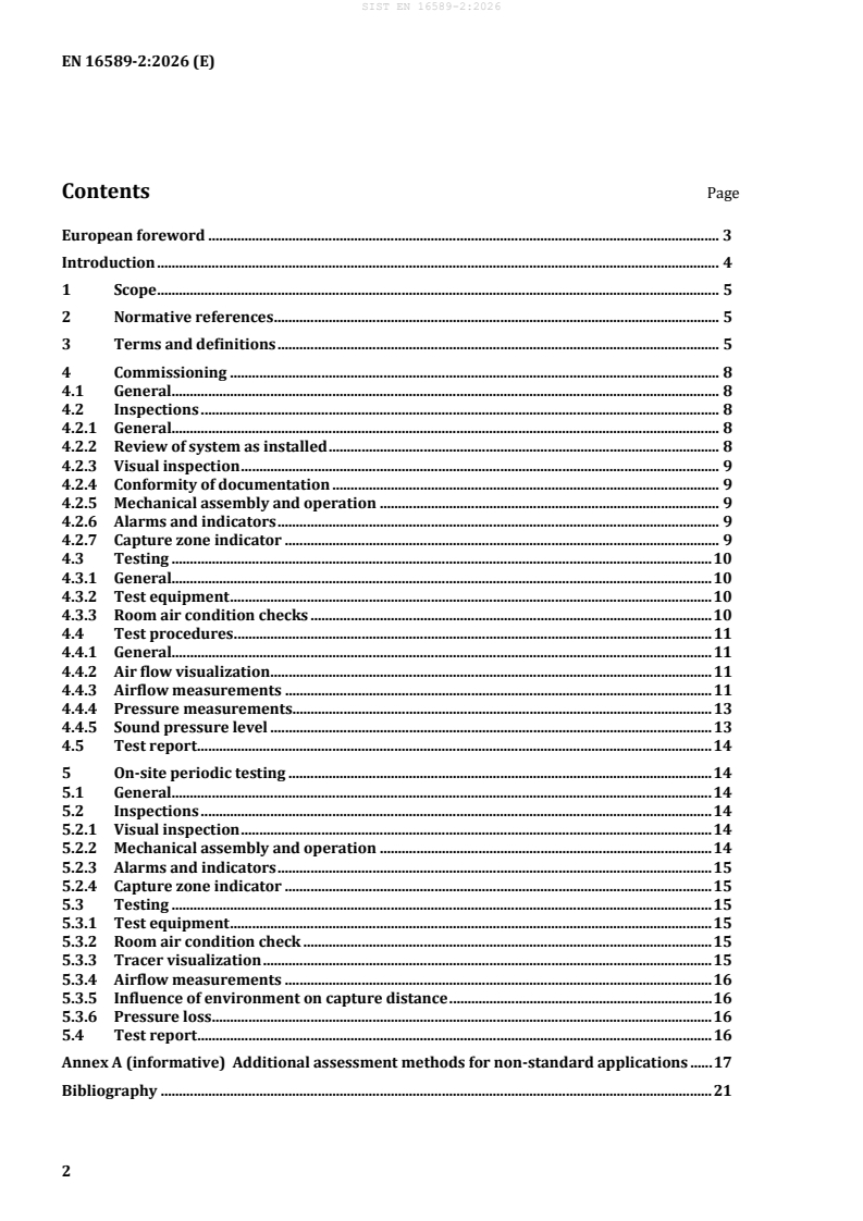
Contents Page
European foreword . 3
Introduction . 4
1 Scope . 5
2 Normative references . 5
3 Terms and definitions . 5
4 Commissioning . 8
4.1 General. 8
4.2 Inspections . 8
4.2.1 General. 8
4.2.2 Review of system as installed . 8
4.2.3 Visual inspection . 9
4.2.4 Conformity of documentation . 9
4.2.5 Mechanical assembly and operation . 9
4.2.6 Alarms and indicators . 9
4.2.7 Capture zone indicator . 9
4.3 Testing . 10
4.3.1 General. 10
4.3.2 Test equipment . 10
4.3.3 Room air condition checks . 10
4.4 Test procedures . 11
4.4.1 General. 11
4.4.2 Air flow visualization . 11
4.4.3 Airflow measurements . 11
4.4.4 Pressure measurements. 13
4.4.5 Sound pressure level . 13
4.5 Test report . 14
5 On-site periodic testing . 14
5.1 General. 14
5.2 Inspections . 14
5.2.1 Visual inspection . 14
5.2.2 Mechanical assembly and operation . 14
5.2.3 Alarms and indicators . 15
5.2.4 Capture zone indicator . 15
5.3 Testing . 15
5.3.1 Test equipment . 15
5.3.2 Room air condition check . 15
5.3.3 Tracer visualization . 15
5.3.4 Airflow measurements . 16
5.3.5 Influence of environment on capture distance . 16
5.3.6 Pressure loss . 16
5.4 Test report . 16
Annex A (informative) Additional assessment methods for non-standard applications . 17
Bibliography . 21
European foreword
This document (EN 16589-2:2026) has been prepared by Technical Committee CEN/TC 332 “Laboratory
equipment”, the secretariat of which is held by DIN.
This European Standard shall be given the status of a national standard, either by publication of an
identical text or by endorsement, at the latest by February 2027, and conflicting national standards shall
be withdrawn at the latest by February 2027.
Attention is drawn to the possibility that some of the elements of this document may be the subject of
patent rights. CEN shall not be held responsible for identifying any or all such patent rights.
Any feedback and questions on this document should be directed to the users’ national standards body.
A complete listing of these bodies can be found on the CEN website.
According to the CEN-CENELEC Internal Regulations, the national standards organisations of the
following countries are bound to implement this European Standard: Austria, Belgium, Bulgaria, Croatia,
Cyprus, Czech Republic, Denmark, Estonia, Finland, France, Germany, Greece, Hungary, Iceland, Ireland,
Italy, Latvia, Lithuania, Luxembourg, Malta, Netherlands, Norway, Poland, Portugal, Republic of North
Macedonia, Romania, Serbia, Slovakia, Slovenia, Spain, Sweden, Switzerland, Türkiye and the United
Kingdom.
Introduction
Articulated extraction arms (AEA) are local exhaust devices consisting of capture devices that can be
constructed in a variety of geometric shapes (hoods, nozzles, flat screens etc.) which are connected to or
mounted on extraction arms or arms with flexible joints. They are used for a variety of different
applications in the laboratory where contaminants are encountered. The design of articulated extract
arms for laboratories can differ for different applications.
The ability of capture devices to capture contaminants is subject to a number of factors. These factors are,
extract volume flow, capture velocity, capture hood design, manoeuvrability, position in relation to
emission source, user activity, air speed etc. The capture ability is rapidly decreased with increased
distance to the emission source. Higher air velocity in the opening of the device improves the capture
ability but commonly results in increased noise level and pressure drop of the capture device and extract
arm.
Good information to the user on how to use the device as well as information about the limitations of the
device are essential for safety and health in the laboratories.
Articulated extract arms are useful for very small emission sources or when the emission source is too
large to reasonably be enclosed but has distinct emission points where the pollution might occur like e.g.
a high-performance liquid chromatography (HPLC).
Type test protocols detailed in EN 16589-1 cannot be replicated on site due to the large variances in room
conditions and AEA positioning.
This document therefore provides methods for Commissioning and Testing of AEAs that will provide
practical detail on the function and basic flow characteristics of air at an installed AEA.
The suitability of an AEA to provide effective ventilation at or near a source of contamination is the
responsibility of the customer and will be subject of a risk assessment. Good practice dictates that full
consideration is given to both local regulatory guidance and hygiene practice.
1 Scope
This document is applicable to test methods designed to be used at the place of installation of the
articulated extraction arms (AEA), usually a laboratory and for various laboratory applications that
require local extraction. They are used for commissioning after installation, for maintenance and for
qualification purposes. For certain customer requirements additional or modified test methods can be
necessary.
This document includes product functional performance referring to product standard detailed in
EN 16589-1. Occupational health and safety assessments methods are not included in this document.
This document does not consider performance requirements for the extract air system associated with
the AEA installation and therefore extract system performance is not part of the scope.
This document does not confirm or establish a capture zone of an AEA capture device only the functional
extract capacity and mechanical functions of the AEA.
2 Normative references
The following documents are referred to in the text in such a way that some or all of their content
constitutes requirements of this document. For dated references, only the edition cited applies. For
undated references, the latest edition of the referenced document (including any amendments) applies.
EN 16211, Ventilation for buildings - Measurement of air flow rates on site – Methods
EN 16589-1:2022, Laboratory local exhaust devices - Part 1: General requirements and type test methods
for articulated extraction arms
EN ISO 5167-1, Measurement of fluid flow by means of pressure differential devices inserted in circular
cross-section conduits running full - Part 1: General principles and requirements (ISO 5167-1)
EN ISO 11204, Acoustics - Noise emitted by machinery and equipment - Determination of emission sound
pressure levels at a work station and at other specified positions applying accurate environmental
corrections (ISO 11204)
3 Terms and definitions
For the purposes of this document, the terms and definitions given in EN 16589-1 and the following apply.
ISO and IEC maintain terminology databases for use in standardization at the following addresses:
— ISO Online browsing platform: available at https://www.iso.org/obp/ui
— IEC Electropedia: available at https://www.electropedia.org/
3.1
capture device
equipment designed to capture or collect air pollutants near their source connected directly to a duct or
mounted on an extraction arm
EXAMPLE hood, flat screen, suction nozzle
[SOURCE: EN 16589-1:2022, 3.1, modified]
3.2
extraction arm
fixed, flexible or articulated ducting connecting the capture device with the main extract air duct
[SOURCE: EN 16589-1:2022, 3.2]
3.3
articulated extraction arm
AEA
articulated extract ducting assembly including capture device
Note 1 to entry: The articulated extraction arm can be moved and positioned so that the capture zone of the hood
is located at the identified hazard release zone. See examples in Figure 1.
Key
ν schematic capture zone
a centre point of entry plane
b duct of capture device
c duct connecting to main duct
1 main duct
2 articulated extraction arms
3 entry plane
4 capture device
Figure 1 — Example of common designs of capture devices and extraction arms
[SOURCE: EN 16589-1:2022, 3.3]
3.4
capture zone
three-dimensional space in front of the entry surface of a capture device in which the air velocity is
greater than or equal to the minimum air velocity required for effective capture of pollutants
[SOURCE: EN 16589-1:2022, 3.4, modified – “plane” replaced with “surface”]
3.5
entry plane
plane touching the outermost parts of the capture device regardless of the shape
Note 1 to entry: A schematic expression of entry plane independent of the shape is given in Figure 1 and Figure 2.
[SOURCE: EN 16589-1:2022, 3.5, modified – Reference to Figure 2 instead of Figure 3]
3.6
measurement plane
two-dimensional area in front of the capture device and parallel to the entry surface used in type testing
Note 1 to entry: Distance from the measuring position to the entry surface is specified in the air velocity
measurement procedure for type tests. A schematic layout showing position of the measurement plane in relation
to the entry plane is included in Figure 2.
Key
1 capture device
2 duct of capture device
3 entry plane
4 measurement plane (as used for type test evaluation)
5 centre line
D internal diameter of the duct of the capture device
L measurement plane distance from the capture device entry surface specified in the air velocity
mp
measurement procedure
Figure 2 — Schematic layout showing position of the measurement plane in relation to the entry
plane
[SOURCE: EN 16589-1:2022, 3.5, modified – Numbering of figure adjusted to document]
3.7
capture velocity
air velocity that is equal to the minimum air velocity required for effective capture of pollutants
3.8
capture distance
distance from the AEA at which the capture velocity (0,2 m/s or 0,4 m/s) is present
3.9
reachable workspace
three-dimensional workspace in which the positioning of the entry plane is achievable with movement
of an articulated extraction arm
Note 1 to entry: The capture zone extract volume flow can vary with changes in the articulated extraction arm
configuration.
[SOURCE: EN 16589-1:2022, 3.8]
3.10
operational working zone
space where the activity or process generates the contaminant cloud to be removed by the capture device
4 Commissioning
4.1 General
The following test methods are considered to be appropriate for the commissioning test after installation
of an AEA (or multiple AEAs on the same extract system) which has been type tested in accordance with
EN 16589-1 prior to installation. It is the aim of commissioning testing to show the correct supply and
installation of the AEA (or multiple AEA’s on the same extract system) and to check adverse effects of the
AEA location, intended extract position, room airflow, the house air extract system and other ventilated
devices on the performance of the installed AEAs connected to the extract system.
Commissioning testing activities shall be carried out using a selection of test methods detailed in this
document.
Consideration should be given to guidance given in CEN/TS 17441 and EN 16589-1:2022, Annex A.
NOTE Consultation between professional parties at system design stage and commissioning is essential to
ensure the AEA System will operate effectively within the environment it is intended.
4.2 Inspections
4.2.1 General
The following items, 4.2.2 and 4.2.3, shall be proven by inspection.
4.2.2 Review of system as installed
It is the customers responsibility to ensure that the extract air system is suitable for AEA devices fitted.
Verify that extract air system has been commissioned according to AEA requirements detailed by the AEA
manufacturer.
Check and record design parameters such as:
— transition detail between AEA assembly and house extract;
— pressure;
— volume flow;
— concurrency / multiple AEA setup;
— temperature range.
4.2.3 Visual inspection
A visual inspection of the assembly and installation shall be carried out in accordance with
manufacturer’s instructions (such as manual or datasheet supplied with system).
— system labelling (identification and conformity label);
— manufactures’ identification.
4.2.4 Conformity of documentation
Review manufacturer’s documentation to verify conformity to EN 16589-1.
4.2.5 Mechanical assembly and operation
Check mechanical assembly and stability of AEA referring to system manual or specification document.
— Check for system completeness in accordance with manufacturers documentation.
— Identify connection arrangement to extract system and mounting detail.
— Where possible, check fixture to extract air system is secure.
— Check AEA achieves maximum and minimum reach as specified by the manufacturer.
— Check the hold stability at maximum and minimum reach positions – AEA to hold position without
additional support.
— Inspect all movable parts (bends, retention sections such as gas struts and springs).
— Check for damage to any part of the AEA device.
4.2.6 Alarms and indicators
Identify alarm / indicator type (visual indication, pressure or flow) and location.
— Check that indicator of the airflow or the air pressure is installed on the AEA.
— Check alarm associated with this indicator is installed.
— Check function is in accordance with EN 16589-1.
4.2.7 Capture zone indicator
If capture zone indicator is fitted, check indicator works as described in user manual.
4.3 Testing
4.3.1 General
The purpose of the following test protocols is to establish a set of test results that will establish that an
AEA is operating within manufactures specifications in the position or positions in which the AEA will be
used.
Another aim is to obtain reference values for comparison in subsequent routine tests.
Testing shall be carried out under the conditions of the expected configuration and use (single or multiple
AEAs in operation at any one time). For example, where there are multiple AEAs expected to be used at
the same time then testing shall take place with those multiple AEAs in operation.
4.3.2 Test equipment
The following test equipment shall be used:
— Low velocity anemometer, suitable for measuring air velocities in the range 0,05 m/s to 3 m/s with
an accuracy of 0,02 m/s ± 5 % of the reading or better, with a response t
...