

ISO/TS 25213:2026
(Main)Robotics — Test methods for measuring the energy consumption of robots — 6-Axis articulated industrial robots
- Abstract
This document specifies methods of measuring energy consumption for a 6-axis, articulated, industrial robot for typical applications. It further specifies the conditions for the measurements and how the results of the measurements are presented. This document does not apply to service robots and medical, SCARA, AMRs and DELTA robots.
- Status
- Published
- Publication Date
- 15-Sep-2026
- Technical Committee
- ISO/TC 299 - Robotics
- Drafting Committee
- ISO/TC 299 - Robotics
- Current Stage
- 6060 - International Standard published
- Start Date
- 16-Sep-2026
- Due Date
- 12-Aug-2026
- Completion Date
- 16-Sep-2026
ISO/TS 25213:2026 is an ISO Technical Specification for measuring the energy consumption of 6-axis articulated industrial robots in typical applications. It specifies how to set up the test, carry out stationary and moving measurements, and present the results. The document is for people who need comparable energy data for robot selection, testing, or reporting, and it excludes service robots, medical robots, SCARA, AMRs and DELTA robots.
What does ISO/TS 25213:2026 specify?
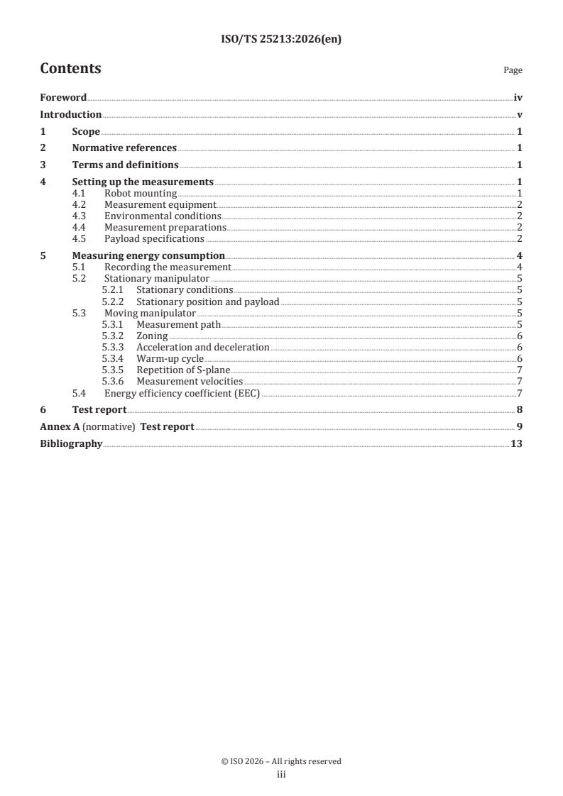
ISO/TS 25213:2026 specifies a test method for measuring the energy consumption of a 6-axis articulated industrial robot, together with the measurement conditions and the way results are reported. The document is organized into six clauses and a normative Annex A for the test report.
- Clause 1 states the scope.
- Clause 2 covers normative references.
- Clause 3 gives the key terms.
- Clause 4 sets out measurement setup requirements.
- Clause 5 describes the energy-consumption tests and the energy efficiency coefficient.
- Clause 6 defines the test report.
- Annex A gives the report structure and required tables.
In practice, this structure helps a lab or manufacturer run the same robot test in the same way and record results in a consistent format.
What are the key requirements of ISO/TS 25213:2026?
Test setup and measurement equipment
ISO/TS 25213:2026 requires the robot to be floor-mounted according to the manufacturer's instructions, fully assembled, operational, leveled and aligned. The power measurement point is between the facility power supply and the robot controller input, so the test focuses on the robot itself rather than attached application equipment.
The measuring system should record power and time, accept a trigger signal, and measure bidirectional flow if regenerative power is used. Its frequency range should reach 5 kHz, with channel accuracy better than 1% in the 1 to 200 A range and better than 5% in the 0 to 1 A range. This matters because short power peaks and energy recovery can otherwise be missed.
Environmental conditions and payloads
ISO/TS 25213:2026 requires the ambient temperature to be stated in the report, and the robot and instruments should be thermally stable before testing. They should also be protected from draughts and external heat sources.
The measurements are repeated with two payloads: 100% of rated payload, and a specified measurement load chosen from the load class tables. If the required centre of gravity cannot be met, the achievable value is used and recorded. This makes the results traceable to the robot's payload capability and helps compare robots fairly.
Stationary measurements
ISO/TS 25213:2026 requires stationary measurements before moving tests, because the robot starts from the lowest energy state. The stationary conditions are brakes disengaged, brakes engaged, and optionally sleep if the robot can do it.
For the stationary position, the upper arm is set at 45° from horizontal and the wrist stays horizontal. The data are recorded for 1 minute. This gives a baseline for power use while the robot is idle, waiting, or powered down in different ways.
Moving measurements
ISO/TS 25213:2026 uses the S-plane path for moving measurements. The path is based on a cube in the working space, with the largest usable cube reduced by 20%, and the largest fitting cube class selected. Zoning is set to 0 mm and stop time to 0 s.
The manufacturer should use maximum permissible acceleration and deceleration, then report the settings used. A warm-up cycle is required before testing, with different minimum times for lower and higher load classes. The robot is then tested at maximum speed and, if possible, at 1600, 1000, 500 and 100 mm/s, from fastest to slowest. This matters because speed and motion profile strongly affect energy use.
Energy efficiency coefficient
ISO/TS 25213:2026 defines an optional energy efficiency coefficient (EEC). It compares the energy actively consumed during motion with the mechanical work done on the payload over a defined path.
The EEC test uses the upward diagonal S4-S3, follows the same speed and repetition rules as the moving test, and is repeated with two payloads. Lower EEC values mean less energy is used for the same payload motion, which helps compare different robots or operating settings.
What terms does ISO/TS 25213:2026 define?
- S-plane - the measurement path on the selected cube in the robot workspace.
- Brakes disengaged - the motors are on, the motor brakes are open and the controller is on.
- Brakes engaged - the motors are off, the motor brakes are engaged and the controller is on.
- Sleep - the motors are off, the motor brakes are engaged, and both the controller and computer are asleep.
- Energy efficiency coefficient (EEC) - a dimensionless indicator that relates consumed energy to the mechanical work performed on the payload.
- Load class - the payload grouping used to select the appropriate measurement load for the robot's rated payload.
Who uses ISO/TS 25213:2026?
ISO/TS 25213:2026 is used by robot manufacturers, test laboratories, system integrators, quality managers and buyers who need comparable energy-consumption data. They use it to set up the robot, choose the test payloads, run stationary and moving measurements, and prepare a report that can be checked or repeated by others.
Which standards are used with ISO/TS 25213:2026?
ISO/TS 25213:2026 names ISO 9283 as the related standard. ISO 9283 provides the general performance-criteria and related test-method framework for manipulating industrial robots, and this document adapts its cube concept for the S-plane measurement path.
What does the ISO/TS 25213:2026 document contain?
The document contains the test setup requirements, payload class tables, measurement equipment parameters, motion-path rules, repetition criteria, speed settings, and the optional EEC calculation method. Figures show the load coordinate system, the measurement process, the stationary position, and the cube/S-plane construction.
Annex A provides the report template, with tables for general robot information, manipulator and controller data, environmental and electrical conditions, instrumentation, stationary results, moving-test settings, and optional EEC reporting. It also requires the robot programmes and software parameters used in each test to be included.
Get Certified
Connect with accredited certification bodies for this standard

DVS-ZERT GmbH
German welding certification society.
CARES (UK Certification Authority for Reinforcing Steels)
UK certification for reinforcing steels and construction.
EWF/IIW (European/International Welding Federation)
International welding personnel certification.
Sponsored listings
Frequently Asked Questions
ISO/TS 25213:2026 is a technical specification published by the International Organization for Standardization (ISO). Its full title is "Robotics — Test methods for measuring the energy consumption of robots — 6-Axis articulated industrial robots". This standard covers: This document specifies methods of measuring energy consumption for a 6-axis, articulated, industrial robot for typical applications. It further specifies the conditions for the measurements and how the results of the measurements are presented. This document does not apply to service robots and medical, SCARA, AMRs and DELTA robots.
This document specifies methods of measuring energy consumption for a 6-axis, articulated, industrial robot for typical applications. It further specifies the conditions for the measurements and how the results of the measurements are presented. This document does not apply to service robots and medical, SCARA, AMRs and DELTA robots.
ISO/TS 25213:2026 is classified under the following ICS (International Classification for Standards) categories: 25.040.30 - Industrial robots. Manipulators. The ICS classification helps identify the subject area and facilitates finding related standards.
ISO/TS 25213:2026 is available in PDF format for immediate download after purchase. The document can be added to your cart and obtained through the secure checkout process. Digital delivery ensures instant access to the complete standard document.
Standards Content (Sample)
Technical
Specification
ISO/TS 25213
First edition
Robotics — Test methods for
2026-09
measuring the energy consumption
of robots — 6-Axis articulated
industrial robots
Robotique — Méthodes d'essai pour mesurer la consommation
d'énergie des robots — Robots industriels 6 axes
Reference number
© ISO 2026
All rights reserved. Unless otherwise specified, or required in the context of its implementation, no part of this publication may
be reproduced or utilized otherwise in any form or by any means, electronic or mechanical, including photocopying, or posting on
the internet or an intranet, without prior written permission. Permission can be requested from either ISO at the address below
or ISO’s member body in the country of the requester.
ISO copyright office
CP 401 • Ch. de Blandonnet 8
CH-1214 Vernier, Geneva
Phone: +41 22 749 01 11
Email: copyright@iso.org
Website: www.iso.org
Published in Switzerland
ii
Contents Page
Foreword .iv
Introduction .v
1 Scope . 1
2 Normative references . 1
3 Terms and definitions . 1
4 Setting up the measurements . 1
4.1 Robot mounting .1
4.2 Measurement equipment.2
4.3 Environmental conditions .2
4.4 Measurement preparations .2
4.5 Payload specifications .2
5 Measuring energy consumption. 4
5.1 Recording the measurement .4
5.2 Stationary manipulator .5
5.2.1 Stationary conditions .5
5.2.2 Stationary position and payload .5
5.3 Moving manipulator .5
5.3.1 Measurement path .5
5.3.2 Zoning .6
5.3.3 Acceleration and deceleration .6
5.3.4 Warm-up cycle .6
5.3.5 Repetition of S-plane . .7
5.3.6 Measurement velocities .7
5.4 Energy efficiency coefficient (EEC) .7
6 Test report . 8
Annex A (normative) Test report . 9
Bibliography .13
iii
Foreword
ISO (the International Organization for Standardization) is a worldwide federation of national standards
bodies (ISO member bodies). The work of preparing International Standards is normally carried out through
ISO technical committees. Each member body interested in a subject for which a technical committee
has been established has the right to be represented on that committee. International organizations,
governmental and non-governmental, in liaison with ISO, also take part in the work. ISO collaborates closely
with the International Electrotechnical Commission (IEC) on all matters of electrotechnical standardization.
The procedures used to develop this document and those intended for its further maintenance are described
in the ISO/IEC Directives, Part 1. In particular, the different approval criteria needed for the different types
of ISO document should be noted. This document was drafted in accordance with the editorial rules of the
ISO/IEC Directives, Part 2 (see www.iso.org/directives).
ISO draws attention to the possibility that the implementation of this document may involve the use of (a)
patent(s). ISO takes no position concerning the evidence, validity or applicability of any claimed patent
rights in respect thereof. As of the date of publication of this document, ISO had not received notice of (a)
patent(s) which may be required to implement this document. However, implementers are cautioned that
this may not represent the latest information, which may be obtained from the patent database available at
www.iso.org/patents.ISO shall not be held responsible for identifying any or all such patent rights.
Any trade name used in this document is information given for the convenience of users and does not
constitute an endorsement.
For an explanation of the voluntary nature of standards, the meaning of ISO specific terms and expressions
related to conformity assessment, as well as information about ISO's adherence to the World Trade
Organization (WTO) principles in the Technical Barriers to Trade (TBT), see www.iso.org/iso/foreword.html.
This document was prepared by Technical Committee ISO/TC 299, Robotics.
Any feedback or questions on this document should be directed to the user’s national standards body. A
complete listing of these bodies can be found atwww.iso.org/members.html.
iv
Introduction
There is significant global focus on energy savings, which also impact the field of robotics. To contribute
to this worldwide effort, this document outlines how to measure the energy consumption of a 6-axis,
[1]
articulated, industrial robot for typical applications. It supports ISO 9283 , which provides an overview of
how to measure the performance criteria and related test methods.
[1]
While ISO 9283 does not specify how to measure energy consumption, this document provides criteria
for how to set up, run and report energy consumption results and calculate energy efficiency while the robot
is moving, waiting and standing still.
v
Technical Specification ISO/TS 25213:2026(en)
Robotics — Test methods for measuring the energy
consumption of robots — 6-Axis articulated industrial robots
1 Scope
This document specifies methods of measuring energy consumption for a 6-axis, articulated, industrial
robot for typical applications. It further specifies the conditions for the measurements and how the results
of the measurements are presented.
This document does not apply to service robots and medical, SCARA, AMRs and DELTA robots.
2 Normative references
There are no normative references in this document.
3 Terms and definitions
For the purposes of this document, the following terms and definitions apply.
ISO and IEC maintain terminology databases for use in standardization at the following addresses:
— ISO Online browsing platform: available at https:// www .iso .org/ obp
— IEC Electropedia: available at https:// www .electropedia .org/
3.1
S-plane
plane in a cube with defined measurement of the sides
3.2
brakes disengaged
state in which the motors are on, the motor brakes are open and the controller is on
Note 1 to entry: The brakes are disengaged when the robot is in an active state.
3.3
brakes engaged
state in which the motors are off, the motor brakes are engaged and the controller is on
Note 1 to entry: The brakes are engaged during, for example, lunch breaks or while waiting for the next cycle to start.
3.4
sleep
state in which the motors are off, the motor brakes are engaged and the controller and computer are asleep
Note 1 to entry: Sleep occurs during weekends or overnight.
4 Setting up the measurements
4.1 Robot mounting
The robot shall be mounted on the floor in accordance with the manufacturer's instructions.
The robot shall be completely assembled and fully operational. All necessary levelling operations, alignment
procedures and functional measurements shall be completed.
4.2 Measurement equipment
The measurement equipment should observe the parameters outlined in Table 1. The energy consumption
measurement points are between the primary power supply section between the facility power supply and
the robot controller power input. The test does not include associated application equipment such as machine
tools or automation with control-related power requirements, which can be sensitive to power fluctuations.
Table 1 — Measurement equipment parameters
Parameter Requirement Required
Appropriate to the grid
Measuring range voltage Optional
system
Measuring range Appropriate to the robot
Optional
current system
Measuring range
5kHz≤ Yes
frequency
Maximum measurement
error of all channels in < 1% Yes
the range 1 to 200 A
Maximum measurement
error of all channels in < 5% Yes
the range 0 to 1A
Able to record power
Recording ability Yes
and time
Recording or inception
Trigger signal Yes
measurement
Able to measure the Optional, required if a
Bi-directional meter directional flow to find regenerative power unit
the regenerative power is used
4.3 Environmental conditions
The manufacturer shall state the ambient temperature during the measurement procedure in the final
report found in Annex A.
4.4 Measurement preparations
The robot and the measuring instruments should be in the measurement environment long enough
(preferably overnight) so that they are in a thermally stable condition before beginning. They shall be
protected from draughts and external thermal radiation (e.g. sunlight, heaters).
4.5 Payload specifications
The measurement shall be repeated with two separate payloads. First, use with 100% of the rated payload
according to the manufacturer. Second, use the specified measurement load according to the load class.
Every robot falls into a certain load class based on its rated payload as specified in Table 2. The measurement
mass is specified under the measurement load group in Table 3, along with the centre of gravity of the load
in relation to the centre of the mounting area on the robot. If the robot is not able to fulfil the measurement's
mass centre of gravity requirements as specified in Table 3, then it should go down to the robot's maximum
measurement mass centre of gravity that it can fulfil. This value should be recorded in the test report (see
Annex A). A technical drawing of the test payload should be included in the
...