

oSIST prEN 13001-3-2:2026
(Main)Cranes - General design - Part 3-2: Limit states and proof of competence of steel wire ropes
- Abstract
This European Standard is to be used together with EN 13001-1 and EN 13001-2 and as such they specify general conditions, requirements and methods to prevent mechanical hazards of wire ropes in cranes by design and theoretical verification.
NOTE Specific requirements for particular types of cranes are given in the appropriate European Standard for the particular crane type.
The following is a list of significant hazardous situations and hazardous events that could result in risks to persons during intended use and reasonably foreseeable misuse. Clauses 5 to 6 of this standard are necessary to reduce or eliminate risks associated with the following hazard:
− exceeding the limits of strength (yield, ultimate, fatigue).
This document does not apply to fibre ropes.
This European Standard is not applicable to cranes which are manufactured before the date of its publication as EN and serves as reference base for the European Standards for particular crane types (see Annex C).
EN 13001-3-2 deals only with the limit state method in accordance with EN 13001-1.
- Status
- Not Published
- Public Enquiry End Date
- 29-Nov-2026
- Technical Committee
- DTN - Lift and transport appliances
- Current Stage
- 4020 - Public enquire (PE) (Adopted Project)
- Start Date
- 02-Sep-2026
- Due Date
- 20-Jan-2027


oSIST prEN 13001-3-2:2026 is the Slovenian draft version of CEN prEN 13001-3-2, published by SIST. It specifies how to design and theoretically verify steel wire ropes in cranes using the limit state method, together with EN 13001-1 and EN 13001-2. The document is aimed at crane designers, manufacturers, verifiers and others who need to check wire rope strength, fatigue and, where relevant, multilayer spooling.
What does oSIST prEN 13001-3-2:2026 specify?
oSIST prEN 13001-3-2:2026 specifies general conditions, requirements and calculation methods to prevent mechanical hazards of steel wire ropes in cranes by design and theoretical verification. The scope is focused on strength-related hazards, especially exceeding the limits of yield, ultimate and fatigue strength, and it covers running ropes and stationary ropes separately.
The document is used together with EN 13001-1 and EN 13001-2. It is organized into general clauses, a dedicated section for running ropes, a dedicated section for stationary ropes, and annexes that provide calculation factors, bending-cycle methods, a standards overview and the link to Regulation (EU) 2023/1230.
| Annex | What it covers |
|---|---|
| Annex A | Specific influences on the effective rope force, including rope reeving efficiency, non-parallel falls, horizontal forces and multi-rope grabs |
| Annex B | Number of relevant bending cycles, including a graphical method and examples |
| Annex C | Overview of standards published by CEN/TC 147 |
| Annex ZA | Relationship with the essential requirements of Regulation (EU) 2023/1230 |
The scope is limited to steel wire ropes in cranes. Fibre ropes are outside the document. The standard also serves as a reference base for European Standards for particular crane types.
What are the key requirements of oSIST prEN 13001-3-2:2026?
The key requirement is to verify the rope by the limit state method only, in line with EN 13001-1. In practice, that means the designer must calculate design rope forces, compare them with limit design rope forces, and do this for the actual rope installation and duty of the crane.
General rules for all ropes
Clause 4 requires the steel wire rope to meet EN 12385-1 and EN 12385-4. Rope terminations must comply with one or more of the termination standards listed there, and they must avoid extra bending and extra stresses close to the termination. This matters because the end connection can reduce the rope strength and can change the decisive proof.
Clause 4 also limits the rope grade used in the document and requires verification if a higher-strength wire rope construction is used. That means the calculation method cannot be applied blindly to every rope; the rope construction, material and behaviour must support the assumptions behind the proof.
The document treats the proof of competence as a safety verification against spontaneous failure and short-term fatigue failure. It also expects the operating manual and service plan to reflect the assumptions of the design proof, including inspection and discarding practice.
Running ropes
Clause 5 covers running ropes, which are ropes wound on drums and bent over sheaves and drums. For running ropes, three proofs can be needed: static strength, fatigue strength and, where applicable, competence for multilayer spooling.
For static strength, the design rope force is built from the rope load, dynamic effects, reeving efficiency and other rope-force increasing effects. Clause 5 links this to the load combinations in EN 13001-2 and adds extra loads such as travel resistance force and rope pre-tensioning force. In practice, this means the calculated rope force must reflect how the drive is actually arranged, not just the lifted mass.
For fatigue strength, Clause 5 uses a synthetic S-N-curve approach with a reference point and a rope force history parameter. Annex B is used to count relevant bending cycles along the rope section that is most unfavourably loaded. This matters because the critical rope section is not always the section with the most obvious motion or the shortest path.
Clause 5 also requires the designer to account for factors that change fatigue behaviour, such as rope grade, fleet angle, lubrication and groove geometry. These effects are handled through the adjustment factors in the clause and the detailed factors in Annex A and Annex B.
For multilayer spooling, Clause 5 adds a separate proof for ropes wound in more than one layer on a drum. The proof addresses wear, plastic deformation and rope crushing in crossover areas. In practice, this is a separate check for multilayer drums, especially when the mechanism and rope type create severe contact conditions.
Stationary ropes
Clause 6 covers stationary ropes, which are fixed at both ends and are mainly loaded in tension. For simple bracings, the rope may be treated as a tension element with its actual stiffness. For more complex rope structures, the clause calls for a more advanced structural calculation when deformations significantly influence the internal forces.
Stationary ropes need static strength proof and fatigue strength proof. The fatigue proof is based on cyclic tensile loads rather than bending over sheaves and drums. If a rope is used as a stationary rope in one phase and as a running rope in another, the proofs from Clauses 5 and 6 must be combined.
What terms does oSIST prEN 13001-3-2:2026 define?
- running rope - A rope wound on and off a drum and bent over sheaves and/or drums, so bending is the main load effect and tension is secondary.
- stationary rope - A rope fixed at both ends in the crane structure, mainly loaded in tension and not wound on a drum or bent over a sheave.
- rotation-resistant rope (RR) - A stranded rope designed to produce reduced torque and rotation when loaded.
- standard rope (SR) - The simplified type designation used for single-layer ropes and parallel-closed ropes.
- design life - The intended service period of the crane or component, based on the original design specification and the expected load spectrum.
- work cycle - The operating sequence from hoisting a load through transfer, lowering, grounding, detaching and returning to the starting position.
Who uses oSIST prEN 13001-3-2:2026?
The document is relevant for machine manufacturers, especially crane designers and rope-drive engineers who need to size and verify steel wire ropes. It is also used by health and safety bodies such as regulators, accident prevention organizations and market surveillance teams.
Machine users, employers, service providers and maintenance teams use it when they need to understand the design assumptions behind inspection intervals, discard criteria and rope replacement decisions. Buyers and quality managers use it when they need to check that a crane design or component specification includes the correct rope verification method for the intended crane type.
What changed in oSIST prEN 13001-3-2:2026 from the previous edition?
oSIST prEN 13001-3-2:2026 supersedes EN 13001-3-2:2014. The foreword states these significant technical changes:
- clearer separation between running ropes and stationary ropes
- a revised fatigue verification concept based on a parameterised synthetic S-N-curve model
- explicit consideration of probability of survival in fatigue verification
- introduction of a low-cycle fatigue limit through the Donandt-force
- revised rope force history parameter and spectrum factor, with clearer rules for relevant bending cycles and critical rope sections
- consolidation of rope force increasing factors into a dedicated annex
- replacement of empirical multilayer-drum reduction factors with a separate proof of competence for multilayer spooling
- updated normative references and Annex ZA to align with EN 13001-1, EN 13001-2 and Regulation (EU) 2023/1230
Which standards are used with oSIST prEN 13001-3-2:2026?
The normative references define the rope products, terminations and general crane design rules that this document relies on.
| Standard | What it contributes |
|---|---|
| EN 12385-1 | General safety requirements for steel wire ropes |
| EN 12385-2 | Definitions, designation and classification of steel wire ropes |
| EN 12385-4 | Stranded ropes for general lifting applications |
| EN 13001-1 | General principles and requirements for crane design |
| EN 13001-2 | Load actions used in crane design verification |
| EN 13411-3 | Ferrules and ferrule-securing terminations |
| EN 13411-4 | Metal and resin socketing |
| EN 13411-6 | Asymmetric wedge socket |
| EN 13411-8 | Swage terminals and swaging |
| EN ISO 12100 | Risk assessment and risk reduction principles for machinery design |
What does the oSIST prEN 13001-3-2:2026 document contain?
The document contains the full calculation framework for rope verification, including the flow chart for the limit state method, the load-combination rules, and the formulas for design rope force and limit design rope force. It also contains the detailed annex material needed to apply those formulas in practice.
Annex A gives the rope force increasing factors for reeving efficiency, non-parallel falls, horizontal forces and multi-rope grabs. Annex B gives the method and worked examples for counting relevant bending cycles in reeving systems, including graphical examples for different rope drive layouts.
The main text also contains the reference S-N-curve concept for fatigue verification, the rules for choosing the decisive rope bending diameter and the factors used for rope grade, fleet angle, lubrication and groove geometry. In practice, that means the standard is both a design document and a calculation guide for verification files, technical checks and crane documentation.
Annex C helps the reader place this part in the wider CEN/TC 147 crane standard family. Annex ZA links the normative clauses to Regulation (EU) 2023/1230 for users who need a harmonized standard route to conformity assessment.
Relations
- Effective Date
- 28-Jan-2026
- Effective Date
- 28-Jan-2026
- Effective Date
- 28-Jan-2026
- Effective Date
- 28-Jan-2026
- Effective Date
- 06-Aug-2025
Frequently Asked Questions
oSIST prEN 13001-3-2:2026 is a draft published by the Slovenian Institute for Standardization (SIST). Its full title is "Cranes - General design - Part 3-2: Limit states and proof of competence of steel wire ropes". This standard covers: This European Standard is to be used together with EN 13001-1 and EN 13001-2 and as such they specify general conditions, requirements and methods to prevent mechanical hazards of wire ropes in cranes by design and theoretical verification. NOTE Specific requirements for particular types of cranes are given in the appropriate European Standard for the particular crane type. The following is a list of significant hazardous situations and hazardous events that could result in risks to persons during intended use and reasonably foreseeable misuse. Clauses 5 to 6 of this standard are necessary to reduce or eliminate risks associated with the following hazard: − exceeding the limits of strength (yield, ultimate, fatigue). This document does not apply to fibre ropes. This European Standard is not applicable to cranes which are manufactured before the date of its publication as EN and serves as reference base for the European Standards for particular crane types (see Annex C). EN 13001-3-2 deals only with the limit state method in accordance with EN 13001-1.
This European Standard is to be used together with EN 13001-1 and EN 13001-2 and as such they specify general conditions, requirements and methods to prevent mechanical hazards of wire ropes in cranes by design and theoretical verification. NOTE Specific requirements for particular types of cranes are given in the appropriate European Standard for the particular crane type. The following is a list of significant hazardous situations and hazardous events that could result in risks to persons during intended use and reasonably foreseeable misuse. Clauses 5 to 6 of this standard are necessary to reduce or eliminate risks associated with the following hazard: − exceeding the limits of strength (yield, ultimate, fatigue). This document does not apply to fibre ropes. This European Standard is not applicable to cranes which are manufactured before the date of its publication as EN and serves as reference base for the European Standards for particular crane types (see Annex C). EN 13001-3-2 deals only with the limit state method in accordance with EN 13001-1.
oSIST prEN 13001-3-2:2026 is classified under the following ICS (International Classification for Standards) categories: 21.220.20 - Cable or rope drives and their components; 53.020.20 - Cranes. The ICS classification helps identify the subject area and facilitates finding related standards.
oSIST prEN 13001-3-2:2026 has the following relationships with other standards: It is inter standard links to SIST EN ISO 14607:2025, SIST EN ISO 12736-1:2023, SIST EN ISO 13997:2025, SIST EN ISO 13997:2023, SIST EN 13001-3-2:2014. Understanding these relationships helps ensure you are using the most current and applicable version of the standard.
oSIST prEN 13001-3-2:2026 is associated with the following European legislation: EU Directives/Regulations: 2023/1230; Standardization Mandates: M/605. When a standard is cited in the Official Journal of the European Union, products manufactured in conformity with it benefit from a presumption of conformity with the essential requirements of the corresponding EU directive or regulation.
oSIST prEN 13001-3-2:2026 is available in PDF format for immediate download after purchase. The document can be added to your cart and obtained through the secure checkout process. Digital delivery ensures instant access to the complete standard document.
Standards Content (Sample)
SLOVENSKI STANDARD
01-oktober-2026
Žerjavi - Konstrukcija, splošno - 3-2. del: Mejna stanja in dokaz varnosti jeklenih
vrvi
Cranes - General design - Part 3-2: Limit states and proof of competence of steel wire
ropes
Krane - Konstruktion allgemein - Teil 3-2: Grenzzustände und Sicherheitsnachweis von
Stahldrahtseilen
Appareils de levage à charge suspendue - Conception générale - Partie 3-2 : Etats
limites et vérification d'aptitude des câbles en acier
Ta slovenski standard je istoveten z: prEN 13001-3-2
ICS:
21.220.20 Vrvni pogoni in njihovi deli Cable or rope drives and
their components
53.020.20 Dvigala Cranes
2003-01.Slovenski inštitut za standardizacijo. Razmnoževanje celote ali delov tega standarda ni dovoljeno.
DRAFT
EUROPEAN STANDARD
NORME EUROPÉENNE
EUROPÄISCHE NORM
October 2026
ICS 21.220.20; 53.020.20 Will supersede EN 13001-3-2:2014
English Version
Cranes - General design - Part 3-2: Limit states and proof
of competence of steel wire ropes
Appareils de levage à charge suspendue - Conception Krane - Konstruktion allgemein - Teil 3-2:
générale - Partie 3-2 : Etats limites et vérification Grenzzustände und Sicherheitsnachweis von
d'aptitude des câbles en acier Stahldrahtseilen
This draft European Standard is submitted to CEN members for enquiry. It has been drawn up by the Technical Committee
CEN/TC 147.
If this draft becomes a European Standard, CEN members are bound to comply with the CEN/CENELEC Internal Regulations
which stipulate the conditions for giving this European Standard the status of a national standard without any alteration.
This draft European Standard was established by CEN in three official versions (English, French, German). A version in any other
language made by translation under the responsibility of a CEN member into its own language and notified to the CEN-CENELEC
Management Centre has the same status as the official versions.
CEN members are the national standards bodies of Austria, Belgium, Bulgaria, Croatia, Cyprus, Czech Republic, Denmark, Estonia,
Finland, France, Germany, Greece, Hungary, Iceland, Ireland, Italy, Latvia, Lithuania, Luxembourg, Malta, Netherlands, Norway,
Poland, Portugal, Republic of North Macedonia, Romania, Serbia, Slovakia, Slovenia, Spain, Sweden, Switzerland, Türkiye and
United Kingdom.
Recipients of this draft are invited to submit, with their comments, notification of any relevant patent rights of which they are
aware and to provide supporting documentation.
Warning : This document is not a European Standard. It is distributed for review and comments. It is subject to change without
notice and shall not be referred to as a European Standard.
EUROPEAN COMMITTEE FOR STANDARDIZATION
COMITÉ EUROPÉEN DE NORMALISATION
EUROPÄISCHES KOMITEE FÜR NORMUNG
CEN-CENELEC Management Centre: Rue de la Science 23, B-1040 Brussels
© 2026 CEN All rights of exploitation in any form and by any means reserved Ref. No. prEN 13001-3-2:2026 E
worldwide for CEN national Members.
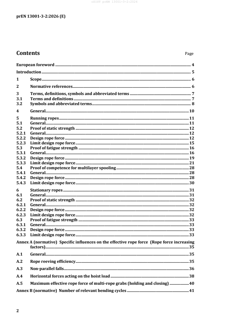
Contents Page
European foreword . 4
Introduction . 5
1 Scope . 6
2 Normative references . 6
3 Terms, definitions, symbols and abbreviated terms . 7
3.1 Terms and definitions . 7
3.2 Symbols and abbreviated terms . 8
4 General. 10
5 Running ropes . 11
5.1 General. 11
5.2 Proof of static strength . 12
5.2.1 General. 12
5.2.2 Design rope force . 12
5.2.3 Limit design rope force . 15
5.3 Proof of fatigue strength . 16
5.3.1 General. 16
5.3.2 Design rope force . 19
5.3.3 Limit design rope force . 21
5.4 Proof of competence for multilayer spooling . 28
5.4.1 General. 28
5.4.2 Design rope force . 28
5.4.3 Limit design rope force . 30
6 Stationary ropes . 31
6.1 General. 31
6.2 Proof of static strength . 32
6.2.1 General. 32
6.2.2 Design rope force . 32
6.2.3 Limit design rope force . 32
6.3 Proof of fatigue strength . 33
6.3.1 General. 33
6.3.2 Design rope force . 33
6.3.3 Limit design rope force . 33
Annex A (normative) Specific influences on the effective rope force (Rope force increasing
factors) . 35
A.1 General. 35
A.2 Rope reeving efficiency . 35
A.3 Non-parallel falls . 36
A.4 Horizontal forces acting on the hoist load . 38
A.5 Maximum effective rope force of multi-rope grabs (holding and closing) . 40
Annex B (normative) Number of relevant bending cycles . 41
B.1 General . 41
B.2 One method to determine the distribution of relevant number of bending cycles in a
reeving system . 43
Annex C (informative) Overview of standards published by CEN/TC 147 . 52
C.1 General . 52
C.2 Selecting a suitable standard . 52
Annex ZA (informative) Relationship between this European Standard and the essential
requirements of Regulation (EU) 2023/1230 aimed to be covered . 54
Bibliography . 62
European foreword
This document (prEN 13001-3-2:2026) has been prepared by Technical Committee CEN/TC 147 “Cranes
– Safety”, the secretariat of which is held by SFS.
This document is currently submitted to the CEN Enquiry.
This document will supersede EN 13001-3-2:2014.
EN 13001-3-2:2014:
— restructuring of the document with a clear separation between provisions for running ropes and
stationary ropes;
— fundamental revision of the fatigue verification concept, introducing a parameterised synthetic S-N-
curve model with a defined reference point, variable slope of S-N-curves depending on D/d, and
explicit consideration of probability of survival;
— introduction of a protection against low-cycle fatigue failure (Donandt-force limit), limiting the
admissible fatigue design rope force;
— revision of the rope force history parameter and spectrum factor, including clarified rules for the
determination of relevant bending cycles and critical rope sections;
— consolidation of rope force increasing factors (e.g. reeving efficiency, non-parallel falls, horizontal
forces) into a dedicated annex;
— replacement of empirical reduction factors for multilayer drums by a separate proof of competence
for multilayer spooling, differentiated by crane type, rope type and type of mechanism;
— update of normative references and Annex ZA to align with EN 13001-1:2015, EN 13001-2:2021 and
Regulation (EU) 2023/1230 (Machinery Regulation).
This document has been prepared under a standardization request addressed to CEN by the European
Commission. The Standing Committee of the EFTA States subsequently approves these requests for its
Member States.
For the relationship with EU Legislation, see informative Annex ZA, which is an integral part of this
document.
For the relationship with other European Standards for cranes, see Annex C.
Introduction
This document has been prepared to be a harmonized standard to provide one means for the mechanical
design and theoretical verification of cranes to conform with the essential health and safety requirements
of the Machinery Regulation, as mentioned in Annex ZA.
This document is a type-C standard as stated in EN ISO 12100:2010.
This document is of relevance, in particular, for the following stakeholder groups representing the market
players with regard to safety of machinery:
— machine manufacturers (small, medium and large enterprises);
— health and safety bodies (regulators, accident prevention organizations, market surveillance, etc.).
Others can be affected by the level of machinery safety achieved with the means of the document by the
above-mentioned stakeholder groups:
— machine users/employers (small, medium and large enterprises);
— machine users/employees (e.g. trade unions, organizations for people with special needs);
— service providers, e.g. for maintenance (small, medium and large enterprises);
— consumers (in case of machinery intended for use by consumers).
The above-mentioned stakeholder groups have been given the possibility to participate in the drafting
process of this document.
The machinery concerned and the extent to which hazards, hazardous situations or hazardous events are
covered are indicated in the Scope of this document.
When requirements of this type-C standard are different from those which are stated in type-A or type-B
standards, the requirements of this type-C standard take precedence over the requirements of the other
standards for machines that have been designed and built according to the requirements of this type-C
standard.
1 Scope
This document is to be used together with EN 13001-1 and EN 13001-2 and as such together they specify
a proof of competence to prevent from mechanical hazards caused by failure of steel wire ropes in cranes
by theoretical verification.
NOTE 1 Specific requirements for particular types of cranes are given in the appropriate European Standard for
the particular crane type.
The following significant hazardous situations and hazardous events could result in risks to persons
during intended use and reasonably foreseeable misuse:
— exceeding the limits of strength (yield, ultimate, fatigue).
Depending on the installation of the rope, application of Clause 5 (in case of running rope) or Clause 6 (in
case of stationary rope) of this document is necessary to reduce or eliminate these risks.
This document does not apply to fibre ropes.
This document is not applicable to cranes which are manufactured before the date of its publication as
EN and serves as reference for the European Standards for particular crane types.
NOTE 2 This document specifies requirements for a verification method in accordance with the limit state
method according to EN 13001-1 only.
2 Normative references
The following documents are referred to in the text in such a way that some or all of their content
constitutes requirements of this document. For dated references, only the edition cited applies. For
undated references, the latest edition of the referenced document (including any amendments) applies.
EN 12385-1:2002+A1:2008, Steel wire ropes — Safety — Part 1: General requirements
EN 12385-2:2002+A1:2008, Steel wire ropes — Safety — Part 2: Definitions, designation and classification
EN 12385-4:2002+A1:2008, Steel wire ropes — Safety — Part 4: Stranded ropes for general lifting
applications
EN 13001-1:2015, Cranes — General design — Part 1: General principles and requirements
EN 13001-2:2021, Crane safety — General design — Part 2: Load actions
EN 13411-3:2022, Terminations for steel wire ropes — Safety — Part 3: Ferrules and ferrule-securing
EN 13411-4:2021, Terminations for steel wire ropes — Safety — Part 4: Metal and resin socketing
EN 13411-6:2004+A1:2008, Terminations for steel wire ropes — Safety — Part 6: Asymmetric wedge
socket
EN 13411-8:2011, Terminations for steel wire ropes — Safety — Part 8: Swage Terminals and Swaging
EN ISO 12100:2010, Safety of machinery — General principles for design — Risk assessment and risk
reduction (ISO 12100:2010)
3 Terms, definitions, symbols and abbreviated terms
3.1 Terms and definitions
For the purposes of this document, the terms and definitions given in EN ISO 12100:2010,
EN 12385-2:2002+A1:2008 and the following apply.
ISO and IEC maintain terminology databases for use in standardization at the following addresses:
— ISO Online browsing platform: available at https://www.iso.org/obp
— IEC Electropedia: available at https://www.electropedia.org/
3.1.1
running rope
rope which is wound on and off a drum and bent over sheaves and/or drums, therefore stressed mainly
by bending and secondly by tension
3.1.2
stationary rope
rope fixed at both ends in the crane structure, primarily under tensile load, and which is not subject to
winding on a drum or bending over a sheave
3.1.3
rotation-resistant rope (RR)
stranded rope designed to generate reduced levels of torque and rotation when loaded
Note 1 to entry: According to ISO 17893:2004+A1:2010 rotation resistant ropes are categorised into 3 groups
regarding their rotational behaviour.
[SOURCE: EN 12385-2:2002+A1:2008, 3.6.1.3]
3.1.4
single-layer rope
stranded rope consisting of one layer of strands laid helically around a core
[SOURCE: EN 12385-2:2002+A1:2008, 3.6.1.2]
3.1.5
parallel-closed rope
stranded rope consisting of at least two layers of strands laid helically in one closing operation around a
strand or fibre centre
[SOURCE: EN 12385-2:2002+A1:2008, 3.6.1.2]
3.1.6
standard rope (SR)
simplified type designation consisting of single-layer ropes and parallel closed ropes
3.1.7
design life
estimation of the intended period of use for a crane, or component based on its original design
specification and taking into consideration the load spectrum expected during its intended use
Note 1 to entry: According to ISO 4301-1, a rope is considered to be a component in this document.
[SOURCE: ISO 12482:2014, 3.2, modified]
3.1.8
work cycle
operating sequence starting from hoisting a load, transferring the load, lowering and grounding the load,
detaching the load and moving the unloaded load lifting attachment back to a starting position ready to
hoist another load
[SOURCE: ISO 12482:2014, 3.6]
3.1.9
rope bending diameter
diameter of the axis of the rope in the state when bent over a sheave or a drum
3.2 Symbols and abbreviated terms
The main symbols used in this document are given in ISO 4301-1, EN 12385-2:2002+A1:2008,
EN 13001-1, EN 13001-2 and Table 1.
Table 1 — Symbols
Symbols Description
a Acceleration or deceleration
C Total number of work cycles during design life of a crane
C Total number of work cycles during the design life of a rope
r
D Rope bending diameter of drum or sheave
d Nominal rope diameter
F Rope tension force
F Horizontal force acting on the hoist load
h
F Minimum breaking force of the rope
min
F Limit design rope force for the proof of fatigue strength
Rd,f
F Limit design rope force for multilayer spooling
Rd,m
F Limit design rope force for the proof of static strength
Rd,s
Reference rope force value to describe the ordinate value of the reference
F
ref
point of the S-N-curve (Wöhler-curve) at the proof of fatigue strength
F Design rope force for the proof of fatigue strength
Sd,f
F Design rope force for multilayer spooling
Sd,m
F Design rope force for the proof of static strength
Sd,s
f Adjustment factor to the reference rope tension force F
F ref
Symbols Description
f Rope force increasing factor
S
*
f Adapted rope force increasing factor at the proof of fatigue strength
S
f Reduction factor effecting the minimum breaking force of the rope
R
f Adjustment factor to the reference number of bending cycles w
w ref
g Acceleration due to gravity
k Rope force spectrum factor
r
l Number of ropes assumed to be used during the design life of the crane
r
m Exponent, slope of the S-N-curve (Wöhler-curve)
m Mass of the hoist (gross) load
H
m Mass of the portion of the suspended ropes of the hoist drive
R
N Number of tensile force cycles at reference point
ref
N Total number of tensile force cycles during the design life of a crane
t
Number of contact points passed by a part of the rope that initiates a
n
change of curvature in the rope
n Number of tensile force cycles
n Mechanical advantage
m
n Number of fixed sheaves between drum and moving part
s
q(z) Normalized position density
R Rope grade
r
r Groove radius
g
S Design load effect in particular rope
r
s Rope force history parameter
r
w Number of bending cycles
w Bending count of a particular type of bending
c
Reference number of bending cycles to describe the abscissa value of the S-
w
ref
N-curve (Wöhler-curve) for the proof of fatigue strength
Total number of bending cycles during the design life of a rope in the rope
w
tot
section
z Position coordinates
α Deflection angle
β Angle between falls and line of action of force
γ Angle between direction of gravity and rope projected in plane of F and g
h
γ General resistance factor
m
γ Risk coefficient
n
γ Partial safety factor
p
Symbols Description
γ Resulting rope resistance factor
rb
γrb,0 Basic rope resistance factor
Factor to adapt the minimum breaking force of the rope F to the
min
γ
ref
reference rope tension force F at the proof of fatigue strength
ref
γ Rope resistance factor to be used at the proof of fatigue strength
rf
γ Rope resistance factor to prevent from exceeding the Donandt-force
rfD
γ Specific resistance factor
s
δ Fleet angle
ε Angle between sheave planes
η Efficiency of applied rope, sheave and bearing
s
ηtot Total rope reeving efficiency of the rope drive
ν Relative total number of cycles
r
ϕ Dynamic factor for inertial and gravity effects
Adapted dynamic factor for inertial effects at the proof of fatigue strength
ϕ*
and multilayer spooling
ω Groove opening angle
Index Description
i, j, k Run index
min, max Index for indicating the minimum, maximum value of a variable
4 General
The steel wire rope shall meet the requirements specified in EN 12385-1:2002+A1:2008 and
EN 12385-4:2002+A1:2008.
For the application of this document, the rope grade 2160 as specified in EN 12385-4:2002+A1:2008
shall not be exceeded.
For wire ropes made from wires with a nominal strength higher than rope grade 2160, the calculation
method and parameters specified in this document shall only be applied where their applicability to the
rope construction concerned has been verified. The verification shall demonstrate that the assumptions
underlying the proof of competence remain valid.
NOTE 1 The selection of steel wire ropes can involve characteristics that are not part of the calculation method
specified in this document, such as rope construction, material, lubrication, galvanising, etc. These characteristics
can influence input values used in the proof of competence or can be subject to requirements specified in other
documents, e.g. EN 12385-1, EN 12385-4 or crane-type-specific standards.
Rope terminations shall meet the requirements of one or several of the following standards:
EN 13411-3:2022, EN 13411-4:2021, EN 13411-6:2004+A1:2008, EN 13411-8:2011.
Rope terminations shall be such that bending of the rope adjacent to the termination and other additional
stresses on the rope are eliminated.
For non-rotation resistant ropes, the end termination shall be made in such a way that it is not possible
for the rope to twist around the longitudinal axis. For rotation resistant ropes, a swivel may be integrated
in the end termination to relieve any twist induced into the rope reeving system.
Running ropes are subject to considerable wear and tear and generally have a significantly shorter
service life than the cranes in which they are used. The proof of competence described in this document
only serves to demonstrate a sufficient level of safety to prevent spontaneous failure and short-term
fatigue failure. Based on the assumptions of this proof of competence, requirements for the inspection
and discarding of the wire rope shall be specified.
NOTE 2 The standard ISO 4309:2017 is no prerequisite for the application of this document, but a means of
ensuring the safe operation of the crane or hoist. Rather, the assumed service life for the proof of fatigue strength is
the input value for determining frequency (resp. time interval) of the periodic inspection of the rope in service.
NOTE 3 The standard ISO 4309:2017 describes the state of the art regarding the inspection of steel wire ropes
and assessing their state of wear in service.
NOTE 4 The standard EN 13135:2026 provides general design requirements for wire ropes in rope drives in
cranes.
5 Running ropes
5.1 General
Running ropes are used in rope drives in which specific effects can occur depending on the rope drive
design. These effects can influence the rope forces acting in the rope and, consequently, the proofs of
competence specified in this document. The effects relevant to the respective proof of competence are
addressed in the corresponding clauses of this document.
If several independent rope drives act on the load or a structural component, the force in the respective
rope drive shall be determined according to the rules of mechanics.
NOTE 1 Running ropes in cranes are stressed by tensile loads and by bending over sheaves and/or on drum.
These cyclic load effects constitute a cumulative fatigue effect to the rope. In this document this effect is expressed
by the rope force history parameter sr, which is independent of time.
NOTE 2 The method of fatigue strength verification using the rope force history parameter sr described in this
document does not preclude the application of a damage accumulation calculation, e.g. Miner-Original.
NOTE 3 Unlike previous design standards for ropes, this document does not link the diameter of rope sheaves
and drums to the component class (previously mechanism class) in order to allow greater flexibility in the design
of rope drives. However, this does not change the fact that it is advisable to select larger sheave and drum diameters
for rope drives that are used more intensively.
For the proof of fatigue strength, a suitable number of work cycles C shall be assumed, which are to be
r
carried out safely with the rope. This number is usually derived from the number of work cycles of the
crane C and the number of ropes l that are assumed to be used during the service life of the crane or
r
hoist. When determining the number of work cycles of the rope C , the operating conditions and the
r
intervals of crane inspections shall be taken into account.
NOTE 4 It is important to note that although the number of bending cycles w is (approximately) proportional
tot
to the number of work cycles C , it depends significantly on the design of the rope drive, e.g. on the number and
r
position of the rope sheaves and the range of displacements (movements). The correlation can be determined by
recording data from comparable types of cranes or by simulation calculations, see B.1.
The following proofs shall be provided for running ropes:
— proof of static strength, see 5.2;
— proof of fatigue strength, see 5.3;
— proof of competence for ropes in multilayer spooling, see 5.4, if applicable.
5.2 Proof of static strength
5.2.1 General
The proof of static strength shall demonstrate compliance with the requirements specified in this clause
regarding:
— a reduction of the minimum breaking force of the rope over its service life; and
— an exceedance of the yield strength of individual wires in the rope.
The proof of static strength according to Formula (1) shall be provided for all relevant load combinations
according to EN 13001-2:2021, as applicable and as amended in this document.
F ≤ F (1)
Sd,s Rd,s
where
FSd,s is the design rope force for the proof of static strength;
F is the limit design rope force for the proof of static strength.
Rd,s
5.2.2 Design rope force
5.2.2.1 General
The rope force considered for the proof of static strength shall be determined from the static rope force
and acceleration forces, the advantage of the reeving and the efficiency of the rope drive, as well as other
rope force increasing effects.
The design rope force F shall be calculated for all load combinations in accordance with
Sd,s
EN 13001-2:2021, Table 13, considering the additional load actions specified in Table 2, as applicable.
5.2.2.2 Hoist rope drives
The design rope force F in hoist rope drives for vertical lifting of loads shall be calculated according
Sd,s
to Formula (2):
mg ⋅
H
Ff⋅⋅φ ⋅ γγ⋅ (2)
∏
Sd,s ijS p n
j
n
m
where
m is the mass of the hoist load including the masses of the payload, load-lifting attachments and
H
the relevant portion of the suspended hoist ropes;
g is the acceleration due to gravity;
n is the mechanical advantage of reeving;
m
φ is the dynamic factor for inertial and gravity effects, see 5.2.2.4;
i
f are the rope force increasing factors, see 5.2.2.5;
Sj
γ is the partial safety factor, see EN 13001-2:2021;
p
γ is the risk coefficient, as applicable, see EN 13001-2:2021;
n
=
i, j are run indices.
NOTE Formula (2) is a simplification of Formula (3) and is only intended for calculating the rope force in hoist
rope drives with a freely swinging load (simple pendulum).
5.2.2.3 General rope drives
Figure 1 illustrates the general determination of the design rope force using the limit state method.
Key
1 load and load combinations according to EN 13001-2:2021, Table 13 and Table 2;
f characteristic load action i acting on the component including dynamic factors φ , see 5.2.2.4;
i i
F combined load actions from load combination j;
j
S design load effects in rope drive k of ropes or rope falls, such as inner forces, resulting from load
k
combination F ;
j
S design load effect in the particular rope as a result of load effects S including rope force increasing factors
r1 k
f , see 5.2.2.5;
Sj
S design load effect in the particular rope arising from local effects, e.g. rope pre-tensioning force (in case this
r2
load effect has not been applied as load action);
FS= resulting design rope force (design load effect) in particular rope;
Sd r
F limit design rope force;
Rd
minimum breaking force of the rope;
F
min
partial safety factors applied to individual load actions according to the load combination under
γ
p
consideration;
γ risk coefficient, where applicable;
n
γ rope resistance factor;
rb
i, j, k are run indices.
Figure 1 — Flow chart of limit state method for the proof of competence of wire ropes
NOTE A flow chart similar to Figure 1 can be found in EN 13001-1:2015, Clause 4.2.7.1, where it is used to
explain the proof of competence of structural parts using the limit state method.
Step '1' in Figure 1 illustrates the creation of the relevant load combinations, which shall be applied on
the mechanical model. It is important that for general rope drives additional load actions shall be
considered, which are not given in EN 13001-2:2021, Table 13. These additional load actions shall be
taken from Table 2. These load actions shall be multiplied with their applicable partial safety factor γ
p
and added to each relevant load combination. Table 2 shall always be used in conjunction with
EN 13001-2:2021, Table 13, where all further information regarding load actions and load combinations
are given.
Table 2 — Additional loads and their partial safety factors γ
p
Categories Load combinations Load combinations Load combinations
Loads, f
i
of loads A B C
Partial safety Partial safety Partial safety
factors γ factors γ factors γ
p p p
Travel resistance
1,34 1,22 1,1
force
Rope pre-
tensioning force
1,22 1,16 1,1
without controlled
Regular
a
application
Rope pre-
tensioning force
1,16 1,1 1,05
with controlled
a
application
a
Controlled application means that the rope pre-tensioning force is quantified, and its application is
measurable, e.g. by a torque wrench.
The design rope force F in general rope drives shall be calculated according to Formula (3):
Sd,s
S
k
F =S=S +=S ⋅ f + S (3)
∏
Sd,s r r1 r2 Sj r2
j
n
m
where
S is the resulting design force in particular rope, see Figure 1;
r
S is the design load effect in particular rope including rope force increasing factors f , see
Sj
r1
5.2.2.5;
S is the design load effect in particular rope arising from local effects;
r2
S is the design load effect in rope drive k of ropes or rope falls, as an inner force, resulting
k
from load combination F ;
j
n is the mechanical advantage of reeving;
m
f are the rope force increasing factors, see 5.2.2.5;
Sj
j is a run index.
5.2.2.4 Inertial and gravitational effects
All inertial and gravitational load actions shall be taken into account with their peak dynamic value
considering the respective dynamic factor φ , as specified in EN 13001-2:2021, Clause 4.2 and Table 13
i
regarding their application in a load combination.
5.2.2.5 Rope force increasing factors
The rope force increasing factors resulting from rope reeving efficiency and other effects occurring
f
Sj
in the rope drive, shall be calculated according to Annex A.
5.2.3 Limit design rope force
The limit design rope force F shall be calculated according to Formula (4):
Rd,s
F
min
F ⋅ min ff; (4)
{ }
Rd,s R1 R2
γ
rb
with
(5)
γ γγ⋅
rb m s
where
F is the specified minimum breaking force of the rope;
min
γ is the rope resistance factor (and results to 2,0);
rb
is the reduction factor due to the type of rope termination, see Table 3;
f
R1
f is the reduction factor due to D/d-ratio of drum or sheave and rope, see Formula (6);
R2
γ is the general resistance factor γ = 1,1, see EN 13001-1:2015, Clause 4.2.7.1;
m
m
is the specific resistance factor γ = 1,82 for a proof of competence against breaking strength
γ s
s
of a wire rope taking into account the decrease of the minimum breaking load over the
operating time as well as exceeding of the yield point of individual wires in the rope.
Table 3 — Reduction factors f
R1
Reduction factors f
Rope termination
R1
Metal sockets 1,0
Resin sockets 1,0
Swage sockets 0,9
Ferrule-secured sockets 0,9
Wedge socketing 0,8
a
Wire rope grips 0,8
a
not allowed for lifting loads
=
=
The rope force reduction factor due to D/d-ratio of drum or sheave and rope diameter shall be
f
R2
calculated as follows:
f 1− (6)
R2
09,
D
( )
d
where
D is the minimum rope bending diameter of drum or sheave in the rope drive;
d is the nominal rope diameter.
The D/d-ratio shall not be chosen less than 10 in order not to fall below the validity range of Formula (6).
If the proof of static strength becomes the decisive proof of competence, a change of the type of the rope
termination can have an influence on the limit design rope force. This information shall be included in
the operating manual of the crane.
NOTE Rope terminations at the drum side using safety windings do not need to be considered as they do not
reduce the breaking force of the rope.
5.3 Proof of fatigue strength
5.3.1 General
The proof of fatigue strength shall demonstrate compliance with the requirements specified in this clause
regarding breakage of individual wires or strands during the service life of the rope due to cyclic bending
of the rope.
NOTE 1 The proof of fatigue strength of running ropes specified in this document is essentially based on the
research of Prof. Klaus Feyrer [1], whereby the logarithmic representation of the lifetime equation developed by
him was converted into the exponential representation of the Miner equation (Formula (7)) commonly used in
mechanical engineering.
The endurable number of bending cycles w shall be calculated according to Formula (7):
−m
F
w w ⋅ (7)
ref
F
ref
where
is the reference number of bending cycles;
w
ref
F is the rope tension force;
F is the reference rope tension force;
ref
m is the exponent, slope of the S-N-curve (Wöhler-curve).
NOTE 2 According to Feyrer [1], the exponent m, the slope of the S-N-curve (Wöhler-curve) in Formula (7),
depends on the quotient of the (relevant) rope bending diameter D in a rope drive and the nominal diameter d of
the rope.
=
=
The exponent m shall be calculated according to Formula (8):
D
m=2,,6⋅−lg 1 6 (8)
d
where
D is the rope bending diameter;
d is the nominal rope diameter.
NOTE 3 The fatigue strength verification according to this document is based on synthetic S-N-curves (Wöhler-
curves) using the breaking strength of the rope and various adjustment factors to determine the reference point,
the characteristic value of the S-N-curves set. According to the research (and regression approach) of Feyrer [1],
the S-N-curves of all D/d-ratios intersect at the reference point. This single point, expressed by the reference rope
force and the reference number of bending cycles, enables a uniform description of the various fatigue strength
lines of the fatigue bending strength of steel wire ropes at different ratios of the rope bending diameter to the rope
diameter.
If S-N-curves (Wöhler-curves) determined by testing are available, these data may replace elements of
this document.
The reference point of the S-N-curves (Wöhler-curves) of a rope in this document is defined as the
characteristic value of fatigue strength against breakage at reference bending cycles under constant force
range loading and with a probability of survival of 97,7 % (mean value minus two standard deviations
obtained at normal distribution and single sided test) valid for all diameter ratios D/d of sheave and rope
within a range between 10 and 63.
The typical fatigue behaviour of a rope for different rope bending diameters D is shown in Figure 2.
Key
X rope bending cycles (logarithmic representation);
Y rope tensile force (logarithmic representation);
1 reference point of fatigue lifetime curves defined by F and w ;
ref ref
2 level of minimum rope breaking force F ;
min
3 Donandt-force, limit value for delimitation from low-cycle fatigue (part of the fatigue lifetime curve
associated with a significant drop of the endurable number of bending cycles);
D , D , D , D , D fatigue lifetime curves with increasing rope bending diameters from D to D and hence an
1 2 3 4 5 1 5
increasing exponent;
Figure 2 — Example of rope fatigue lifetime curves and definition of the reference point
The decisive rope bending diameter D used in Formula (8), shall be chosen as the minimum bending
diameter of any drum or sheave used in the rope drive according to Formula (9):
D = min D (9)
{ }
i
where
D is the rope bending diameter of any drum or sheave (reeving system element) in the rope
i
drive, without compensating sheaves.
The diameter of any sheave or drum in the rope drive shall be selected that the D/d-ratio does not become
less than 10, in order that the validity range of Formula (8) for the exponent m is not exceeded.
Compensation sheaves are not taken into account at the proof of fatigue strength in accordance with this
document, as the rope does not ‘run’ over this sheave. The damaging, fatigue-relevant effects caused by
rope/system vibrations at this point of verification (the two landing points on the compensation sheave)
shall be assessed separately by the designer.
The proof of fatigue strength according to Formula (10) shall be provided for all relevant load
combinations according to EN 13001-2:2021, as applicable and as amended in this document.
FF≤ (10)
Sd,,f Rd f
where
F is the design rope force for the proof of fatigue strength;
Sd,f
F is the limit design rope force for the proof of fatigue strength.
Rd,f
5.3.2 Design rope force
5.3.2.1 General
As with the proof of static strength, the rope force considered for the proof of fatigue strength shall be
determined from the static rope force and acceleration forces, the advantage of the reeving and the
efficiency of the rope drive, as well as other rope force increasing effects.
However, due to the movement of the rope in the rope drive, and thus a change of loading and a shift of
the affected rope section along the rope is occurring, all oscillating components of the rope force during
a work cycle need to be taken into account with their statistical mean values only as they are not equally
effective in all bending cycles.
The design rope force F shall be calculated for load combinations A in accordance with
Sd,f
EN 13001-2:2021, Table 13, considering the additional load actions specified in Table 2, as applicable,
setting all partial safety factors γ = 1,0. Additionally, the dynamic factors may be adapted as specified in
p
Clause 5.3.2.4 and the rope force increasing factors may be adapted as specified in Clause 5.3.2.5.
NOTE In some applications the load effect from load combinations B (occasional loads) or combinations C
(exceptional loads) can occur frequently enough to require inclusion in the fatigue proof.
5.3.2.2 Hoist rope drives
The design rope force F in hoist rope drives for vertical lifting of loads shall be calculated according to
Sd,f
Formula (11):
mg ⋅
H **
Ff⋅⋅φ ∏ ⋅ γγ⋅ (11)
Sd,f i jjS p n
n
m
where
m is the mass of the hoist load including the masses of the payload, load-lifting attachments and
H
the relevant portion of the suspended hoist ropes;
g is the acceleration due to gravity;
n is the mechanical advantage of reeving;
m
*
φ is the adapted dynamic factor for inertial and gravity effects at the proof of fatigue strength,
i
see 5.3.2.4;
*
f are the adapted rope force increasing factors at the proof of fatigue strength, see 5.3.2.5;
Sj
γ is the partial safety factor, γ = 1, see EN 13001-2:2021;
p
p
γ is the risk coefficient, as applicable, see EN 13001-2:2021;
n
=
i, j are run indices.
5.3.2.3 General rope drives
The design rope force F in general rope drives shall be calculated according to Formula (12):
Sd, f
S
k *
F =S=S +=S ⋅ ∏ f + S (12)
Sd,f r r1 r2 jjS r2
n
m
where
S is the resulting design force in particular rope, see F
...