

ISO 19085-10:2026
(Main)Woodworking machines — Safety — Part 10: Building site saws (contractor saws)
- Abstract
This document gives the safety requirements and measures for building site saws, designed to cut wood and materials with similar physical characteristics to wood, capable of continuous production use, hereinafter referred to also as “machines”. This document deals with all significant hazards, hazardous situations or hazardous events, listed in Annex A, relevant to the machines, when it is used as intended and under conditions of misuse which are reasonably foreseeable by the manufacturer. This document is also applicable to the other life cycle phases of the machines: transport, assembly, adjustment, maintenance, dismantling and scrapping. This document applies to a machine that can also be fitted with a device for the saw blade to be manually raised and lowered through the table, whose hazards have been dealt with. This document applies to a machine designed to cut against the feed only. This document does not apply to: machines with a maximum saw blade diameter smaller than 350 mm or greater than 500 mm; hand-held motor-operated electric tools, including any adaptation permitting their use in a different mode, i.e. bench mounting; transportable motor-operated electric tools; machines with a device to tilt the saw blade for angle cutting, machines with more than one saw blade rotational speed and machines equipped with a sliding table. NOTE 1 Hand-held motor-operated electric tools are covered by IEC 62841-1 together with IEC 62841-2-5. NOTE 2 Transportable motor-operated electric tools are covered by IEC 62841-1 together with IEC 62841-3-1. NOTE 3 Machines with the device to tilt the saw blade for angle cutting, machines with more than one saw blade rotational speed and machines equipped with a sliding table are considered as table saws, covered by ISO 19085-9. This document is not applicable to machines intended for use in potentially explosive atmospheres or to machines manufactured prior to the date of its publication.
- Status
- Published
- Publication Date
- 12-Nov-2026
- Technical Committee
- ISO/TC 39/SC 4 - Woodworking machines
- Drafting Committee
- ISO/TC 39/SC 4/WG 2 - Safety of manually fed machines
- Current Stage
- 6060 - International Standard published
- Start Date
- 13-Nov-2026
- Completion Date
- 13-Nov-2026
Buy Documents
ISO 19085-10:2026 - Woodworking machines — Safety — Part 10: Building site saws (contractor saws)
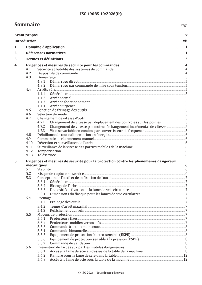
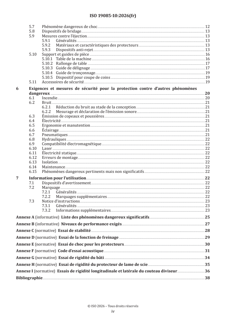
ISO 19085-10:2026 - Machines à bois — Sécurité — Partie 10: Scies de chantier
ISO 19085-10 is an ISO safety standard for building site saws, also called contractor saws, including displaceable machines used to cut wood and materials with similar physical characteristics. It specifies safety requirements and protective measures for designers, manufacturers, suppliers and importers, and it is a type-C standard, so its machine-specific requirements take precedence over type-A and type-B standards where they differ.
What does ISO 19085-10 specify?
ISO 19085-10 specifies safety requirements for building site saws intended for continuous production use, including the machine in intended operation, reasonably foreseeable misuse, and the life-cycle phases of transport, assembly, adjustment, maintenance, dismantling and scrapping. It also covers machines fitted with a device for manually raising and lowering the saw blade through the table, and it applies only to machines designed to cut against the feed.
The standard is organised into Clauses 1 to 7 and Annexes A to I. Annex A lists significant hazards, Annex B summarizes required performance levels, and Annexes C to I give the verification tests for stability, braking, guards, noise, frame rigidity and riving knife rigidity.
| Annex | What it covers |
|---|---|
| A | Informative list of significant hazards |
| B | Informative summary of required performance levels |
| C | Stability test |
| D | Braking function test |
| E | Impact test for guards |
| F | Noise test code |
| G | Frame rigidity test |
| H | Saw blade guard rigidity test |
| I | Riving knife longitudinal and lateral rigidity test |
The scope excludes machines with saw blades smaller than 350 mm or larger than 500 mm, hand-held motor-operated electric tools, transportable motor-operated electric tools, machines with a tilting blade for angle cutting, machines with more than one saw blade rotational speed, and machines with a sliding table. It also excludes machines for potentially explosive atmospheres and machines made before the publication date.
What are the key requirements of ISO 19085-10?
Control functions and stopping
ISO 19085-10 relies on the common control-system requirements in Clause 4, with the performance levels for each safety function summarized in Annex B. In practice, this means the saw's controls, stopping functions and any speed-monitoring function must be designed and verified as safety functions, not as ordinary convenience features.
The normal stop control for the saw blade has to be next to the start control and both have to be on the front side of the machine. That layout matters because the operator can reach the controls quickly without moving around the machine.
ISO 19085-10 allows direct start, but it does not allow starting via control power-on. Operational stop, emergency stop, mode selection, manual reset control, standstill detection and machine-moving-parts speed monitoring are not required for this machine type. Where a frequency inverter is provided, the manufacturer has to preset a fixed speed and monitor it so the drive stops automatically if the speed exceeds the preset value by more than 10 percent.
Mechanical protection and anti-kickback measures
Clause 5 sets the mechanical safety measures, starting with stability. The machine needs integral lifting provisions so it does not overturn during lifting, and any stored parts such as fences must stay in place during lifting. The standard also requires verification by the stability test in Annex C and the frame rigidity test in Annex G.
ISO 19085-10 requires an automatically adjustable saw blade guard above the table. The guard has to be transparent, rest on the table when not in use, rise only as needed during feeding, and pass the rigidity test in Annex H. Its opening and support geometry are controlled so the operator can see the cut while keeping hands away from the blade.
For access below the table, the blade has to be enclosed by fixed guards. If the blade is changed from below the table, the machine needs a movable interlocking guard with guard locking and interlocking to blade rotation. The table slot and any replaceable table insert are also controlled so access remains limited.
To reduce ejection and kickback, guards used for ejection protection must be class B, and the machine must be supplied with a riving knife mounting arrangement and one or more riving knives matched to the blade range. The riving knife has to meet specific material, thickness, positioning and rigidity requirements, and its verification is given in Annex I. In practice, this is the part that keeps the cut open behind the blade and reduces the chance of the workpiece closing on the blade.
Workpiece guidance, safety appliances and user information
ISO 19085-10 requires a machine table, and where needed an extension table, with dimensions given in Table 2. The machine also has to have a rip fence, a cross-cut fence and a wedge cutting device, each with defined materials, adjustment ranges and tool-free adjustment or fastening where required. These requirements matter because the saw is meant to guide the workpiece securely and consistently during ripping, cross-cutting and wedge cutting.
The machine must be supplied with a push block handle and a push stick. The push stick has a minimum length requirement and material requirement, so the user has a safe way to feed small or awkward workpieces without putting hands near the blade.
Clause 6 and Clause 7 deal with the other hazards and the information the user needs. The standard covers noise, chips and dust extraction, electricity, ergonomics, marking and the instruction handbook. Marking includes blade diameter limits, blade rotation direction, bore diameter, riving knife identification, the guaranteed sound power level and a warning sign against tampering with the saw blade guard.
What terms does ISO 19085-10 define?
- Building site saw / contractor saw - a hand-fed machine with a saw blade mounted under the table, designed for outdoor building-site use and equipped with integral lifting provisions.
- Wedge cutting device - a device used to cut wedges with different angles.
- Riving knife - the splitting element behind the blade that helps keep the kerf open and reduces kickback risk.
- Safety-related parts of control systems (SRP/CS) - the parts of the control system that perform safety functions, such as speed monitoring.
- Performance level required (PLr) - the target performance level for a safety function, summarized for this standard in Annex B.
- Safely-limited speed (SLS) - the drive safety function used when a frequency inverter is present and speed has to be monitored.
Who uses ISO 19085-10?
ISO 19085-10 is used by machine manufacturers, designers, suppliers and importers who build or place building site saws on the market. It is also used by health and safety bodies, regulators, accident prevention organisations and market surveillance authorities when checking whether a saw meets the expected safety level.
In practice, machine users, employers and maintenance providers use it to understand how the saw should be guarded, marked, tested and documented. It is also relevant to service providers and, where the machine is intended for consumer use, to consumers who need to understand the safety features and instructions.
What changed in ISO 19085-10 from the previous edition?
ISO 19085-10 is the second edition and it replaces ISO 19085-10:2018. The changes stated for this edition are:
- references to ISO 19085-1:2021 were simplified and the introductory boilerplate was removed
- the scope was revised to state that the machines are intended for continuous production use
- the list of significant hazards was moved to Annex A
- verification sentences were removed where the text is self-evident
- new dimensions for the guard opening were added in 5.6.1
- the machine table and extension table dimensions were moved into 5.10.1
- the wedge cutting device requirements were moved into 5.10.5
- Clause 6.2 was updated and Annex F now gives a full noise test code
Which standards are used with ISO 19085-10?
ISO 19085-10 is intended to be used with ISO 19085-1:2021, which provides the common requirements for woodworking machines. It also depends on the following referenced standards:
- ISO 12100:2010 - the basis for risk assessment and risk reduction
- ISO 13849-1:2023 - safety-related parts of control systems
- ISO 13857:2019 - safety distances to prevent reach into hazard zones
- IEC 60204-1:2016+A1:2021 - electrical equipment of machines
- IEC 61800-5-2:2016 - functional safety for adjustable speed drive systems
What does the ISO 19085-10 document contain?
ISO 19085-10 contains a clause-by-clause safety specification, plus figures, tables and annexes that support design, verification and user information. The main content includes control requirements, mechanical guarding, ejection control, workpiece guidance, noise, dust extraction, ergonomics, marking and instructions for use.
The document also includes:
- Table A.1 on significant hazards and where they are addressed
- Table B.1 on safety functions and required performance levels
- Figures showing guard mounting, riving knife position, fence adjustment and push devices
- Table 2 for the machine table, extension table and table insert dimensions
- Annexes C to I with the verification tests used for design checking, type testing and declaration support
Relations
- Effective Date
- 12-Feb-2026
- Consolidates
ISO 9098-2:2023 - Bunk beds and high beds — Safety requirements and tests — Part 2: Test methods - Effective Date
- 07-Jan-2025
- Revises
ISO 19085-10:2018 - Woodworking machines — Safety — Part 10: Building site saws (contractor saws) - Effective Date
- 07-Jan-2025
Buy Documents
ISO 19085-10:2026 - Woodworking machines — Safety — Part 10: Building site saws (contractor saws)
ISO 19085-10:2026 - Machines à bois — Sécurité — Partie 10: Scies de chantier
Get Certified
Connect with accredited certification bodies for this standard

CIS Institut d.o.o.
Personal Protective Equipment (PPE) certification body. Notified Body NB-2890 for EU Regulation 2016/425 PPE.
Gozdarski inštitut Slovenije
Slovenian Forestry Institute. Forest management certification support, timber testing.

Kiwa BDA Testing
Building and construction product certification.
Sponsored listings
Frequently Asked Questions
ISO 19085-10:2026 is a standard published by the International Organization for Standardization (ISO). Its full title is "Woodworking machines — Safety — Part 10: Building site saws (contractor saws)". This standard covers: This document gives the safety requirements and measures for building site saws, designed to cut wood and materials with similar physical characteristics to wood, capable of continuous production use, hereinafter referred to also as “machines”. This document deals with all significant hazards, hazardous situations or hazardous events, listed in Annex A, relevant to the machines, when it is used as intended and under conditions of misuse which are reasonably foreseeable by the manufacturer. This document is also applicable to the other life cycle phases of the machines: transport, assembly, adjustment, maintenance, dismantling and scrapping. This document applies to a machine that can also be fitted with a device for the saw blade to be manually raised and lowered through the table, whose hazards have been dealt with. This document applies to a machine designed to cut against the feed only. This document does not apply to: machines with a maximum saw blade diameter smaller than 350 mm or greater than 500 mm; hand-held motor-operated electric tools, including any adaptation permitting their use in a different mode, i.e. bench mounting; transportable motor-operated electric tools; machines with a device to tilt the saw blade for angle cutting, machines with more than one saw blade rotational speed and machines equipped with a sliding table. NOTE 1 Hand-held motor-operated electric tools are covered by IEC 62841-1 together with IEC 62841-2-5. NOTE 2 Transportable motor-operated electric tools are covered by IEC 62841-1 together with IEC 62841-3-1. NOTE 3 Machines with the device to tilt the saw blade for angle cutting, machines with more than one saw blade rotational speed and machines equipped with a sliding table are considered as table saws, covered by ISO 19085-9. This document is not applicable to machines intended for use in potentially explosive atmospheres or to machines manufactured prior to the date of its publication.
This document gives the safety requirements and measures for building site saws, designed to cut wood and materials with similar physical characteristics to wood, capable of continuous production use, hereinafter referred to also as “machines”. This document deals with all significant hazards, hazardous situations or hazardous events, listed in Annex A, relevant to the machines, when it is used as intended and under conditions of misuse which are reasonably foreseeable by the manufacturer. This document is also applicable to the other life cycle phases of the machines: transport, assembly, adjustment, maintenance, dismantling and scrapping. This document applies to a machine that can also be fitted with a device for the saw blade to be manually raised and lowered through the table, whose hazards have been dealt with. This document applies to a machine designed to cut against the feed only. This document does not apply to: machines with a maximum saw blade diameter smaller than 350 mm or greater than 500 mm; hand-held motor-operated electric tools, including any adaptation permitting their use in a different mode, i.e. bench mounting; transportable motor-operated electric tools; machines with a device to tilt the saw blade for angle cutting, machines with more than one saw blade rotational speed and machines equipped with a sliding table. NOTE 1 Hand-held motor-operated electric tools are covered by IEC 62841-1 together with IEC 62841-2-5. NOTE 2 Transportable motor-operated electric tools are covered by IEC 62841-1 together with IEC 62841-3-1. NOTE 3 Machines with the device to tilt the saw blade for angle cutting, machines with more than one saw blade rotational speed and machines equipped with a sliding table are considered as table saws, covered by ISO 19085-9. This document is not applicable to machines intended for use in potentially explosive atmospheres or to machines manufactured prior to the date of its publication.
ISO 19085-10:2026 is classified under the following ICS (International Classification for Standards) categories: 13.110 - Safety of machinery; 79.120.10 - Woodworking machines. The ICS classification helps identify the subject area and facilitates finding related standards.
ISO 19085-10:2026 has the following relationships with other standards: It is inter standard links to FprEN ISO 19085-10, ISO 9098-2:2023, ISO 19085-10:2018. Understanding these relationships helps ensure you are using the most current and applicable version of the standard.
ISO 19085-10:2026 is available in PDF format for immediate download after purchase. The document can be added to your cart and obtained through the secure checkout process. Digital delivery ensures instant access to the complete standard document.
Standards Content (Sample)
International
Standard
ISO 19085-10
Second edition
Woodworking machines — Safety —
2026-11
Part 10:
Building site saws (contractor saws)
Machines à bois — Sécurité —
Partie 10: Scies de chantier
Reference number
© ISO 2026
All rights reserved.
This ISO publication is protected by copyright and is owned by ISO and/or its licensors.
The content of this ISO publication is provided under licence, not sold. Use is subject to the applicable licence terms issued by ISO,
an ISO member body, or an authorized third-party distributor.
Except as required for implementation or expressly permitted by a separate licence, no part of this ISO publication may be
reproduced, distributed, modified, used, or made available in any form or by any means – electronic or mechanical, including
photocopying, scanning, recording, or posting on internal or external digital platforms.
Any use beyond the scope of the granted rights is prohibited and may result in legal action.
ISO copyright office
CP 401 • CH-1214 Vernier, Geneva
Phone: +41 22 749 01 11
Email: copyright@iso.org
Website: www.iso.org
Published in Switzerland
ii
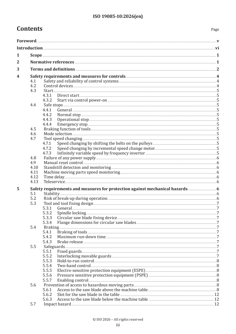
Contents Page
Foreword .v
Introduction .vi
1 Scope . 1
2 Normative references . 1
3 Terms and definitions . 2
4 Safety requirements and measures for controls . 4
4.1 Safety and reliability of control systems.4
4.2 Control devices .4
4.3 Start .5
4.3.1 Direct start .5
4.3.2 Start via control power-on .5
4.4 Safe stops .5
4.4.1 General .5
4.4.2 Normal stop .5
4.4.3 Operational stop .5
4.4.4 Emergency stop .5
4.5 Braking function of tools .5
4.6 Mode selection .5
4.7 Tool speed changing .5
4.7.1 Speed changing by shifting the belts on the pulleys .5
4.7.2 Speed changing by incremental speed change motor .5
4.7.3 Infinitely variable speed by frequency inverter .5
4.8 Failure of any power supply .6
4.9 Manual reset control .6
4.10 Standstill detection and monitoring .6
4.11 Machine moving parts speed monitoring.6
4.12 Time delay.6
4.13 Teleservice .6
5 Safety requirements and measures for protection against mechanical hazards . 6
5.1 Stability .6
5.2 Risk of break-up during operation .6
5.3 Tool and tool fixing design .7
5.3.1 General .7
5.3.2 Spindle locking .7
5.3.3 Circular saw blade fixing device .7
5.3.4 Flange dimensions for circular saw blades .7
5.4 Braking .7
5.4.1 Braking of tools .7
5.4.2 Maximum run-down time .7
5.4.3 Brake release .7
5.5 Safeguards .7
5.5.1 Fixed guards .7
5.5.2 Interlocking movable guards .7
5.5.3 Hold-to-run control .8
5.5.4 Two-hand control .8
5.5.5 Electro-sensitive protection equipment (ESPE) .8
5.5.6 Pressure sensitive protection equipment (PSPE) .8
5.5.7 Enabling control .8
5.6 Prevention of access to hazardous moving parts .8
5.6.1 Access to the saw blade above the machine table .8
5.6.2 Slot for the saw blade in the table . 12
5.6.3 Access to the saw blade below the machine table . 12
5.7 Impact hazard . 12
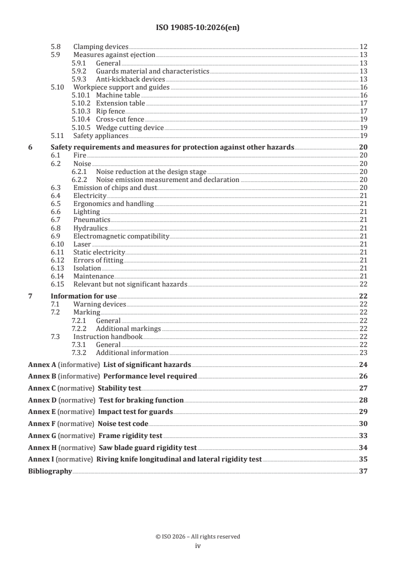
iii
5.8 Clamping devices . 12
5.9 Measures against ejection . 13
5.9.1 General . 13
5.9.2 Guards material and characteristics . 13
5.9.3 Anti-kickback devices . 13
5.10 Workpiece support and guides .16
5.10.1 Machine table .16
5.10.2 Extension table .17
5.10.3 Rip fence . .17
5.10.4 Cross-cut fence .19
5.10.5 Wedge cutting device .19
5.11 Safety appliances .19
6 Safety requirements and measures for protection against other hazards .20
6.1 Fire . 20
6.2 Noise . 20
6.2.1 Noise reduction at the design stage . 20
6.2.2 Noise emission measurement and declaration . 20
6.3 Emission of chips and dust . 20
6.4 Electricity .21
6.5 Ergonomics and handling .21
6.6 Lighting .21
6.7 Pneumatics .21
6.8 Hydraulics .21
6.9 Electromagnetic compatibility.21
6.10 Laser .21
6.11 Static electricity.21
6.12 Errors of fitting .21
6.13 Isolation .21
6.14 Maintenance .21
6.15 Relevant but not significant hazards . 22
7 Information for use .22
7.1 Warning devices . 22
7.2 Marking . 22
7.2.1 General . 22
7.2.2 Additional markings . 22
7.3 Instruction handbook. 22
7.3.1 General . 22
7.3.2 Additional information . 23
Annex A (informative) List of significant hazards .24
Annex B (informative) Performance level required .26
Annex C (normative) Stability test . .27
Annex D (normative) Test for braking function .28
Annex E (normative) Impact test for guards . .29
Annex F (normative) Noise test code . .30
Annex G (normative) Frame rigidity test .33
Annex H (normative) Saw blade guard rigidity test .34
Annex I (normative) Riving knife longitudinal and lateral rigidity test .35
Bibliography .37
iv
Foreword
ISO (the International Organization for Standardization) is a worldwide federation of national standards
bodies (ISO member bodies). The work of preparing International Standards is normally carried out through
ISO technical committees. Each member body interested in a subject for which a technical committee
has been established has the right to be represented on that committee. International organizations,
governmental and non-governmental, in liaison with ISO, also take part in the work. ISO collaborates closely
with the International Electrotechnical Commission (IEC) on all matters of electrotechnical standardization.
The procedures used to develop this document and those intended for its further maintenance are described
in the ISO/IEC Directives, Part 1. In particular, the different approval criteria needed for the different types
of ISO documents should be noted. This document was drafted in accordance with the editorial rules of the
ISO/IEC Directives, Part 2 (see www.iso.org/directives).
ISO draws attention to the possibility that the implementation of this document may involve the use of (a)
patent(s). ISO takes no position concerning the evidence, validity or applicability of any claimed patent
rights in respect thereof. As of the date of publication of this document, ISO had not received notice of (a)
patent(s) which may be required to implement this document. However, implementers are cautioned that
this may not represent the latest information, which may be obtained from the patent database available at
www.iso.org/patents. ISO shall not be held responsible for identifying any or all such patent rights.
Any trade name used in this document is information given for the convenience of users and does not
constitute an endorsement.
For an explanation of the voluntary nature of standards, the meaning of ISO specific terms and expressions
related to conformity assessment, as well as information about ISO's adherence to the World Trade
Organization (WTO) principles in the Technical Barriers to Trade (TBT), see www.iso.org/iso/foreword.html.
This document was prepared by Technical Committee ISO/TC 39, Machine tools, Subcommittee SC 4,
Woodworking machines, in collaboration with the European Committee for Standardization (CEN) Technical
Committee CEN/TC 142, Woodworking machines - Safety, in accordance with the Agreement on technical
cooperation between ISO and CEN (Vienna Agreement).
This second edition cancels and replaces the first edition (ISO 19085-10:2018), which has been technically
revised.
The main changes are as follows:
— the referencing structure to ISO 19085-1:2021 has been simplified;
— the Scope has been revised to specify that machines are intended for continuous production use;
— the list of significant hazards has been moved to a new Annex A;
— the verification methods at the end of each subclause have been deleted;
— requirements on dimensions of the guard opening have been added in 5.6.1 b) and replacing the test
probe figure and dimensions in former Annex K;
— the table and figure for the dimensions of machine table and extension table have been moved from the
former Annex H to 5.10.1;
— the requirements on the wedge cutting device have been moved from 5.11 to the new 5.10.5;
— subclause 6.2 has been updated and a new full noise test code has been added in Annex F.
This document is intended to be used in conjunction with ISO 19085-1:2021.
A list of all parts in the ISO 19085 series can be found on the ISO website.
Any feedback or questions on this document should be directed to the user’s national standards body. A
complete listing of these bodies can be found at www.iso.org/members.html.
v
Introduction
The ISO 19085 series provides technical safety requirements for the design and construction of woodworking
machinery, as well as for the content of the relevant instruction handbook. The ISO 19085 series is intended
for designers, manufacturers, suppliers and importers of the machines specified in the Scope of its parts.
This document is a type-C standard as stated in ISO 12100:2010.
This document is of relevance, in particular, for the following stakeholder groups representing the market
players with regard to machinery safety:
— machine manufacturers (small, medium and large enterprises);
— health and safety bodies (regulators, accident prevention organisations, market surveillance, etc.).
Others can be affected by the level of machinery safety achieved with the means of the document by the
above-mentioned stakeholder groups:
— machine users/employers (small, medium and large enterprises);
— machine users/employees (e.g. trade unions, organizations for people with special needs);
— service providers, for example, for maintenance (small, medium and large enterprises);
— consumers (in the case of machinery intended for use by consumers).
The above-mentioned stakeholder groups have been given the possibility to participate in the drafting
process of this document.
The machinery concerned and the extent to which hazards, hazardous situations or hazardous events are
covered are indicated in the Scope of this document.
When requirements of this type-C standard are different from those which are stated in type-A or type-B
standards, the requirements of this type-C standard take precedence over the requirements of the other
standards for machines that have been designed and built according to the requirements of this type-C
standard.
In this document, a subclause can refer to the same subclause of ISO 19085-1:2021 or give specific
requirements or both. The specific text can be subdivided into further subclauses.
vi
International Standard ISO 19085-10:2026(en)
Woodworking machines — Safety —
Part 10:
Building site saws (contractor saws)
1 Scope
This document gives the safety requirements and measures for building site saws, designed to cut wood and
materials with similar physical characteristics to wood, capable of continuous production use, hereinafter
referred to also as “machines”.
This document deals with all significant hazards, hazardous situations or hazardous events, listed in
Annex A, relevant to the machines, when it is used as intended and under conditions of misuse which are
reasonably foreseeable by the manufacturer.
This document is also applicable to the other life cycle phases of the machines: transport, assembly,
adjustment, maintenance, dismantling and scrapping.
This document applies to a machine that can also be fitted with a device for the saw blade to be manually
raised and lowered through the table, whose hazards have been dealt with.
This document applies to a machine designed to cut against the feed only.
This document does not apply to:
a) machines with a maximum saw blade diameter smaller than 350 mm or greater than 500 mm;
b) hand-held motor-operated electric tools, including any adaptation permitting their use in a different
mode, i.e. bench mounting;
c) transportable motor-operated electric tools;
d) machines with a device to tilt the saw blade for angle cutting, machines with more than one saw blade
rotational speed and machines equipped with a sliding table.
NOTE 1 Hand-held motor-operated electric tools are covered by IEC 62841-1 together with IEC 62841-2-5.
NOTE 2 Transportable motor-operated electric tools are covered by IEC 62841-1 together with IEC 62841-3-1.
NOTE 3 Machines with the device to tilt the saw blade for angle cutting, machines with more than one saw blade
rotational speed and machines equipped with a sliding table are considered as table saws, covered by ISO 19085-9.
This document is not applicable to machines intended for use in potentially explosive atmospheres or to
machines manufactured prior to the date of its publication.
2 Normative references
The following documents are referred to in the text in such a way that some or all of their content constitutes
requirements of this document. For dated references, only the edition cited applies. For undated references,
the latest edition of the referenced document (including any amendments) applies.
ISO 12100:2010, Safety of machinery — General principles for design — Risk assessment and risk reduction
ISO 13849-1:2023, Safety of machinery — Safety-related parts of control systems — Part 1: General principles
for design
ISO 13857:2019, Safety of machinery — Safety distances to prevent hazard zones being reached by upper and
lower limbs
ISO 19085-1:2021, Woodworking machines — Safety — Part 1: Common requirements
I EC 6 020 4 -1:2016 +A 1: 2021, Safety of machinery — Electrical equipment of machines — Part 1: General
requirements
IEC 61800-5-2:2016, Adjustable speed electrical power drive systems — Part 5-2: Safety requirements —
Functional
3 Terms and definitions
For the purposes of this document, the terms and definitions given in ISO 12100:2010, ISO 13849-1:2023,
ISO 19085-1:2021 and the following apply.
ISO and IEC maintain terminology databases for use in standardization at the following addresses:
— ISO Online browsing platform: available at https:// www .iso .org/ obp
— IEC Electropedia: available at https:// www .electropedia .org/
3.1
building site saw
contractor saw
hand-fed machine fitted with a saw blade mounted under the table designed for use on building sites outdoor
and equipped with integral provisions for lifting (e.g. lifting eyes)
Note 1 to entry: The saw blade is mounted on a horizontal spindle below the table. The machine can have the device for
the saw blade to be raised and lowered through the table. An example of a building site saw is given in Figure 1.
a) Building site saw with saw blade guard mounted onto the riving knife
b) Building site saw with saw blade guard mounted separately from the riving knife
Key
1 riving knife
2 saw blade guard
3 saw blade guard support
4 fixed guard beneath table
5 rip fence
6 cross-cut fence
7 machine table
8 controls on the front side
9 push block or push stick
10 extension table
11 table insert
12 chips and dust outlet (for indoor use)
13 lifting eyes
14 cutting height adjustment (optional)
Figure 1 — Examples of a building site saw with different mountings of the saw blade guard
3.2
wedge cutting device
device to cut wedges with different angles
Note 1 to entry: An example of a wedge cutting device is shown in Figure 2.
Key
1 wedge cutting device
2 push stick
Figure 2 — Example of a wedge cutting device
4 Safety requirements and measures for controls
4.1 Safety and reliability of control systems
ISO 19085-1:2021, 4.1 shall apply.
NOTE ISO 19085-1:2021, 4.1 references subclauses of ISO 13849-1:2015, which has since been cancelled
and replaced by ISO 13849-1:2023. The correspondence between the subclauses of ISO 13849-1:2015 cited in
ISO 19085-1:2021, 4.1 and the subclauses with the same content of ISO 13849-1:2023 (cited in this document) is given
in Table 1.
Table 1 — Correspondence of the subclauses of ISO 13849-1:2015 cited in ISO 19085-1:2021, 4.1,
with those in ISO 13849-1:2023
ISO 13849-1:2015 ISO 13849-1:2023
4.6.1 7.1
4.6.2 7.3
4.6.3 7.4
4.7 8
8 10
Table B.1 summarizes the performance levels required (PL ) in Clauses 4 and 5 for each safety function.
r
4.2 Control devices
ISO 19085-1:2021, 4.2 shall apply.
The normal stop control device for the saw blade shall be positioned adjacent to the start control device.
Both shall be positioned on the front side of the machine (see Figure 1).
4.3 Start
4.3.1 Direct start
ISO 19085-1:2021, 4.3.1 shall apply, except the requirement on powered feed, which is not mounted on
building site saws.
4.3.2 Start via control power-on
Starting via control power-on is not relevant to this machine.
4.4 Safe stops
4.4.1 General
ISO 19085-1:2021, 4.4.1 shall apply.
4.4.2 Normal stop
ISO 19085-1:2021, 4.4.2 shall apply.
4.4.3 Operational stop
Operational stop is not relevant to this machine.
4.4.4 Emergency stop
Emergency stop is not relevant to this machine.
4.5 Braking function of tools
ISO 19085-1:2021, 4.5 shall apply.
4.6 Mode selection
Mode selection is not relevant to this machine, which has one operating mode only.
4.7 Tool speed changing
4.7.1 Speed changing by shifting the belts on the pulleys
No change of tool speed is relevant to this machine, which has one fixed value of tool speed only.
4.7.2 Speed changing by incremental speed change motor
No change of tool speed is relevant to this machine, which has one fixed value of tool speed only.
4.7.3 Infinitely variable speed by frequency inverter
If frequency inverter is provided, a speed fixed value shall be pre-set by the machine manufacturer and the
speed shall be monitored.
The control for speed monitoring shall ensure that, as soon as the speed exceeds the pre-set fixed value by
more than 10 %, the drive is stopped automatically in stop category 0 in accordance with IEC 60204-1+A1:
2021: 2016 , 9. 2 . 2 .
The safety related parts of control systems (SRP/CS) for speed monitoring shall achieve PL = c.
r
For speed monitoring of power drive system (safety-related) [PDS(SR)], IEC 61800-5-2:2016, 4.2.4.5 [safely-
limited speed (SLS)], 6.5.4 and 9.2 shall apply.
4.8 Failure of any power supply
ISO 19085-1:2021, 4.8 shall apply.
4.9 Manual reset control
Manual reset control is not relevant to this machine.
4.10 Standstill detection and monitoring
Standstill detection and monitoring are not relevant to this machine.
4.11 Machine moving parts speed monitoring
Machine moving parts speed monitoring is not relevant to this machine.
4.12 Time delay
ISO 19085-1:2021, 4.12 shall apply.
4.13 Teleservice
Teleservice is not relevant to this machine, which has no control computer, therefore it has no connection
capability.
5 Safety requirements and measures for protection against mechanical hazards
5.1 Stability
ISO 19085-1:2021, 5.1 shall apply.
The machine shall be equipped with integral provisions for lifting, so that overturning is prevented during
lifting. If lifting eyes are used for this purpose, use four lifting eyes (see Figure 1 Key 13).
All parts stored on the machines, like fences, shall not fall down during lifting of the machine.
The machine shall pass the stability test required in Annex C.
The machine shall pass the frame rigidity test required in Annex G.
5.2 Risk of break-up during operation
ISO 19085-1:2021, 5.2 shall apply.
The machine table slot shall be lined with easily machinable material (see ISO 19085-1:2021, 3.3).
5.3 Tool and tool fixing design
5.3.1 General
ISO 19085-1:2021, 5.3.1 shall apply.
−2
Saw spindles shall be manufactured from steel with an ultimate tensile strength of at least 580 N mm .
5.3.2 Spindle locking
ISO 19085-1:2021, 5.3.2 shall apply.
5.3.3 Circular saw blade fixing device
ISO 19085-1:2021, 5.3.3 shall apply.
5.3.4 Flange dimensions for circular saw blades
ISO 19085-1:2021, 5.3.4 shall apply.
5.4 Braking
5.4.1 Braking of tools
ISO 19085-1:2021, 5.4.1 shall apply.
The machine shall pass the test for braking function given in Annex D.
5.4.2 Maximum run-down time
ISO 19085-1:2021, 5.4.2 shall apply.
5.4.3 Brake release
ISO 19085-1:2021, 5.4.3 shall apply.
5.5 Safeguards
5.5.1 Fixed guards
ISO 19085-1:2021, 5.5.1 shall apply.
5.5.2 Interlocking movable guards
5.5.2.1 General
ISO 19085-1:2021, 5.5.2.1 shall apply.
5.5.2.2 Movable guards with interlocking
Movable guards with interlocking without guard locking are not relevant to this machine.
5.5.2.3 Movable guards with interlocking and guard locking
ISO 19085-1:2021, 5.5.2.3 shall apply.
5.5.3 Hold-to-run control
Hold-to-run control is not relevant to this machine.
5.5.4 Two-hand control
Two-hand control is not relevant to this machine.
5.5.5 Electro-sensitive protection equipment (ESPE)
No ESPE is relevant to this machine.
5.5.6 Pressure sensitive protection equipment (PSPE)
No PSPE is relevant to this machine.
5.5.7 Enabling control
Enabling control is not relevant to this machine.
5.6 Prevention of access to hazardous moving parts
5.6.1 Access to the saw blade above the machine table
An automatically adjustable guard shall restrict access to the saw blade above the machine table. It shall
be fitted to the riving knife or to the machine separately from the riving knife. In the latter case, it shall be
mounted to the machine with a support not being in line with the riving knife (see Figure 1).
The saw blade guard shall be in accordance with the following requirements.
a) It shall be made of transparent material.
b) A front opening in the guard shall provide an unobstructed view of the saw blade and the cutting line to
a machine operator feeding the material to be cut, and shall fulfil the following requirements.
1) Position and size of the opening shall be such that the operator does not need to assume an unnatural
position, e.g. slouching or bend-over.
2) The maximum width of this opening shall be 35 mm and its distance to the saw blade teeth shall
be at least 50 mm, with the guard on the table and the largest saw blade adjusted to its maximum
height.
3) The upper side of the opening shall not extend beyond the first point of contact of the guard with
the table, in feed direction.
4) Any other opening in the guard shall be in accordance with the safety distance requirements of
ISO 13857:2019.
c) In the area where the saw blade guard can come in contact with the rip fence in the lower position, the
maximum width of the saw blade guard shall not exceed 50 mm.
d) It shall rest on the table when the machine is not in use (see Figures 1 and 6). The pivots in the mounting
arrangement for the saw blade guard shall be designed in such a way that it is not possible to lock the
saw blade guard in an elevated position.
e) The lower inner edges of the sides of the saw blade guard shall be lined with a rib, made of plastic, light
alloy, wood or wood-based materials. This rib shall be a minimum 3 mm in width and shall be designed
so as to prevent the saw blade teeth from cutting into the saw blade guard in case the saw blade guard
is displaced from the line of cut (see Figure 3). If the rib is replaceable, the fixing arrangement shall be
such that it does not damage the saw blade, e.g. with brass screws.
f) It shall be capable of upward movement during workpiece feeding. The vertical force required to open
the saw blade guard, applied to measuring point A in Figure H.1, key 1, shall not exceed 8 N.
g) During workpiece feeding, the bottom of the saw blade guard shall rest on the workpiece (see Figure 6).
h) Any part of the support of the saw blade guard shall be higher of at least 3 mm than the lower edge of the
saw blade guard in its highest position, that is at the maximum cutting capacity (see Figure 4), and the
support shall be provided with an end stop at this position to avoid jamming of the workpiece during
feeding.
i) The mounting arrangement of the saw blade guard shall not be capable of being moved out of position
without the aid of a tool.
j) The in-feed end of the saw blade guard shall have a “lead-in”. If the saw unit is fitted with the maximum
saw blade and raised to the maximum height, the lead-in shall allow the saw blade guard to be raised
by a workpiece with a thickness equal to at least the maximum cutting height for which the machine
is designed plus 2 mm. This can be achieved by an inclination of an angle α of not more than 45° (see
Figure 5).
k) The saw blade guard shall pass the saw blade guard rigidity test in Annex H.
Dimensions in millimetres
Key
1 side walls of the saw blade guard
2 fixing screws
3 ribbings
Figure 3 — Example of replaceable ribs at the underside of saw blade guard side walls
Dimensions in millimetres
Key
1 saw blade guard in its highest position
2 saw blade
3 assembly device with end stop
4 riving knife
Figure 4 — Riving knife mounted saw blade guard in its highest position
Key
α angle
Figure 5 — Design of the “lead-in”
Key
1 top guard support
2 workpiece
3 top guard fixing on riving knife
4 riving knife
5 saw blade
6 direction of feed
7 extraction outlet
Figure 6 — Example of an automatically adjustable saw blade guard
5.6.2 Slot for the saw blade in the table
The total width of the slot, L, (see Figure 7) shall not exceed 12 mm. On the fixed saw flange side of the table,
the distance, D, between the fixed saw flange and the edge of the table slot shall not exceed 3 mm.
Dimensions in millimetres
Key
L total width of the table slot
D distance between the fixed saw flange and the table edge
Figure 7 — Dimensions of the slot for the saw blade in the table
In cases where the saw blade is changed from above the table, a replaceable table insert shall be provided on
the non-fixed flange side and shall:
a) have a minimum width in accordance with the dimension “c” in Table 2 (see 5.10.1);
b) be made of easily machinable material (see ISO 19085-1:2021, 3.3);
c) be held in position such that it would not be dislodged in the event of contact with the saw blade;
d) be able to be dismounted without the use of a tool (e.g. by a wing screw).
5.6.3 Access to the saw blade below the machine table
The access to the saw blade below the table shall be prevented by fixed guards.
If the saw blade is changed from below the table, a movable interlocking guard with guard locking shall be
provided for this purpose and interlocked with the saw blade rotation.
An opening at the bottom of the fixed guards casing shall be provided and be as wide as possible to allow
easy leakage of chips and dust, but shall in any case meet the requirements for safety distances in accordance
with ISO 13857:2019, Table 4.
5.7 Impact hazard
Impact hazard is not relevant to this machine.
5.8 Clamping devices
No clamping device is relevant to this machine.
...
Norme
internationale
ISO 19085-10
Deuxième édition
Machines à bois — Sécurité —
2026-11
Partie 10:
Scies de chantier
Woodworking machines — Safety —
Part 10: Building site saws (contractor saws)
Numéro de référence
DOCUMENT PROTÉGÉ PAR COPYRIGHT
© ISO 2026
Tous droits réservés. Sauf prescription différente ou nécessité dans le contexte de sa mise en œuvre, aucune partie de cette
publication ne peut être reproduite ni utilisée sous quelque forme que ce soit et par aucun procédé, électronique ou mécanique,
y compris la photocopie, ou la diffusion sur l’internet ou sur un intranet, sans autorisation écrite préalable. Une autorisation peut
être demandée à l’ISO à l’adresse ci-après ou au comité membre de l’ISO dans le pays du demandeur.
ISO copyright office
Case postale 401 • Ch. de Blandonnet 8
CH-1214 Vernier, Genève
Tél.: +41 22 749 01 11
E-mail: copyright@iso.org
Web: www.iso.org
Publié en Suisse
ii
Sommaire Page
Avant-propos .v
Introduction .vii
1 Domaine d’application . 1
2 Références normatives . 1
3 Termes et définitions . 2
4 Exigences et mesures de sécurité pour les commandes . 4
4.1 Sécurité et fiabilité des systèmes de commande .4
4.2 Dispositifs de commande .4
4.3 Démarrage .5
4.3.1 Démarrage direct .5
4.3.2 Démarrage par commande de mise sous tension .5
4.4 Arrêts sûrs .5
4.4.1 Généralités .5
4.4.2 Arrêt normal .5
4.4.3 Arrêt de fonctionnement .5
4.4.4 Arrêt d’urgence .5
4.5 Fonction de freinage des outils .5
4.6 Sélection du mode .5
4.7 Changement de vitesse d’outil .5
4.7.1 Changement de vitesse par déplacement des courroies sur les poulies .5
4.7.2 Changement de vitesse par moteur à changement incrémental de vitesse .5
4.7.3 Vitesse variable en continu par convertisseur de fréquence .5
4.8 Défaillance de toute alimentation en énergie .6
4.9 Commande de réarmement manuel.6
4.10 Détection et surveillance de l’arrêt .6
4.11 Surveillance de la vitesse des parties mobiles de la machine .6
4.12 Temporisation .6
4.13 Téléservice .6
5 Exigences et mesures de sécurité pour la protection contre les phénomènes dangereux
mécaniques . 6
5.1 Stabilité .6
5.2 Risque de rupture en service .6
5.3 Conception de l'outil et de la fixation de l’outil .7
5.3.1 Généralités .7
5.3.2 Blocage de l’arbre .7
5.3.3 Dispositif de fixation de la lame de scie circulaire .7
5.3.4 Dimensions du flasque pour les lames de scie circulaires .7
5.4 Freinage .7
5.4.1 Freinage des outils .7
5.4.2 Temps d'arrêt maximal .7
5.4.3 Relâchement du frein .7
5.5 Moyens de protection .7
5.5.1 Protecteurs fixes . .7
5.5.2 Protecteurs mobiles verrouillés .7
5.5.3 Commande à action maintenue .8
5.5.4 Commande bimanuelle .8
5.5.5 Équipement de protection électro-sensible (ESPE) .8
5.5.6 Équipement de protection sensible à la pression (PSPE) .8
5.5.7 Commande de validation .8
5.6 Prévention de l’accès aux parties mobiles dangereuses .8
5.6.1 Accès à la lame de scie au-dessus de la table de la machine .8
5.6.2 Rainure pour la lame de scie dans la table . 12
5.6.3 Accès à la lame de scie sous la table de la machine . 12
iii
5.7 Phénomène dangereux de choc . 12
5.8 Dispositifs de bridage . 13
5.9 Mesures contre l'éjection. 13
5.9.1 Généralités . 13
5.9.2 Matériaux et caractéristiques des protecteurs . 13
5.9.3 Dispositifs anti-rejet . 13
5.10 Support et guides de pièce .16
5.10.1 Table de la machine .16
5.10.2 Rallonge de table .17
5.10.3 Guide de délignage .17
5.10.4 Guide de tronçonnage .19
5.10.5 Dispositif pour coupe de coins .19
5.11 Accessoires de sécurité .19
6 Exigences et mesures de sécurité pour la protection contre d'autres phénomènes
dangereux .20
6.1 Incendie . 20
6.2 Bruit .21
6.2.1 Réduction du bruit au stade de la conception .21
6.2.2 Mesurage et déclaration de l'émission sonore .21
6.3 Émission de copeaux et poussières .21
6.4 Électricité .21
6.5 Ergonomie et manutention .21
6.6 Éclairage .21
6.7 Pneumatiques .21
6.8 Hydrauliques . 22
6.9 Compatibilité électromagnétique . 22
6.10 Laser . 22
6.11 Électricité statique . . 22
6.12 Erreurs de montage. 22
6.13 Isolation . 22
6.14 Maintenance . 22
6.15 Phénomènes dangereux pertinents mais non significatifs . 22
7 Information pour l’utilisation . .22
7.1 Dispositifs d'avertissement . 22
7.2 Marquage . 22
7.2.1 Généralités . 22
7.2.2 Marquages supplémentaires . 22
7.3 Notice d'instructions . . 23
7.3.1 Généralités . 23
7.3.2 Informations supplémentaires . 23
Annexe A (informative) Liste des phénomènes dangereux significatifs.25
Annexe B (informative) Niveaux de performance exigés .27
Annexe C (normative) Essai de stabilité .28
Annexe D (normative) Essai de la fonction de freinage .29
Annexe E (normative) Essai de choc pour les protecteurs .30
Annexe F (normative) Code d’essai acoustique .31
Annexe G (normative) Essai de rigidité du bâti .34
Annexe H (normative) Essai de rigidité du protecteur de lame de scie .35
Annexe I (normative) Essais de rigidité longitudinale et latérale du couteau diviseur .36
Bibliographie .38
iv
Avant-propos
L'ISO (Organisation internationale de normalisation) est une fédération mondiale d'organismes nationaux
de normalisation (comités membres de l'ISO). L'élaboration des Normes internationales est en général
confiée aux comités techniques de l'ISO. Chaque comité membre intéressé par une étude a le droit de faire
partie du comité technique créé à cet effet. Les organisations internationales, gouvernementales et non
gouvernementales, en liaison avec l'ISO participent également aux travaux. L'ISO collabore étroitement avec
la Commission électrotechnique internationale (IEC) en ce qui concerne la normalisation électrotechnique.
Les procédures utilisées pour élaborer le présent document et celles destinées à sa mise à jour sont
décrites dans les Directives ISO/IEC, Partie 1. Il convient, en particulier, de prendre note des différents
critères d'approbation requis pour les différents types de documents ISO. Le présent document a
été rédigé conformément aux règles de rédaction données dans les Directives ISO/IEC, Partie 2 (voir
www.iso.org/directives).
L’ISO attire l’attention sur le fait que la mise en application du présent document peut entraîner l’utilisation
d’un ou de plusieurs brevets. L’ISO ne prend pas position quant à la preuve, à la validité et à l’applicabilité de
tout droit de propriété revendiqué à cet égard. À la date de publication du présent document, l’ISO n'avait pas
reçu notification qu’un ou plusieurs brevets pouvaient être nécessaires à sa mise en application. Toutefois,
il y a lieu d’avertir les responsables de la mise en application du présent document que des informations
plus récentes sont susceptibles de figurer dans la base de données de brevets, disponible à l'adresse
www.iso.org/brevets. L’ISO ne saurait être tenue pour responsable de ne pas avoir identifié tout ou partie de
tels droits de propriété.
Les appellations commerciales éventuellement mentionnées dans le présent document sont données pour
information, par souci de commodité, à l’intention des utilisateurs et ne sauraient constituer un engagement.
Pour une explication de la nature volontaire des normes, la signification des termes et expressions
spécifiques de l'ISO liés à l'évaluation de la conformité, ou pour toute information au sujet de l'adhésion de
l'ISO aux principes de l’Organisation mondiale du commerce (OMC) concernant les obstacles techniques au
commerce (OTC), voir www.iso.org/avant-propos.
Le présent document a été élaboré par le comité technique ISO/TC 39, Machines-outils, sous-comité SC 4
Machines à bois, en collaboration avec le comité technique CEN/TC 142 Machines à bois – Sécurité, du Comité
européen de normalisation (CEN) conformément à l’Accord de coopération technique entre l’ISO et le CEN
(Accord de Vienne).
Cette deuxième édition annule et remplace la première édition (ISO 19085-10:2018), qui a fait l’objet d’une
révision technique.
Les principales modifications sont les suivantes:
— les références à l'ISO 19085-1:2021 ont été simplifiées;
— le Domaine d'application a été révisé pour spécifier que les machines sont destinées à une utilisation en
production continue;
— la liste des phénomènes dangereux significatifs a été déplacée dans une nouvelle Annexe A;
— les méthodes de vérification à la fin de chaque paragraphe ont été supprimées;
— des exigences relatives aux dimensions de l'ouverture du protecteur ont été ajoutées au 5.6.1 b) et
remplaçant la figure et les dimensions de la sonde d'essai dans l'ancienne Annexe K);
— le tableau et la figure concernant les dimensions de la table de la machine et de la rallonge de table ont
été déplacés de l'ancienne Annexe H au 5.10.1;
— les exigences relatives au dispositif pour coupe de coins ont été déplacées du 5.11 au nouveau 5.10.5;
— le paragraphe 6.2 a été mis à jour et un nouveau code d’essai acoustique complet a été ajouté à l’Annexe F.
Le présent document est destiné à être utilisé conjointement avec l'ISO 19085-1:2021.
v
Une liste de toutes les parties de la série ISO 19085 se trouve sur le site web de l’ISO.
Il convient que l’utilisateur adresse tout retour d’information ou toute question concernant le présent
document à l’organisme national de normalisation de son pays. Une liste exhaustive desdits organismes se
trouve à l’adresse www.iso.org/fr/members.html.
vi
Introduction
La série ISO 19085 fournit les exigences techniques de sécurité pour la conception et la fabrication
des machines à bois ainsi que pour le contenu de la notice d'instructions correspondante. La série
ISO 19085 s'adresse aux concepteurs, fabricants, fournisseurs et importateurs des machines spécifiées dans
le Domaine d’application.
Le présent document est une norme de type C tel que mentionné dans l’ISO 12100:2010.
Le présent document concerne, en particulier, les groupes de parties prenantes suivants représentant les
acteurs du marché dans le domaine de la sécurité des machines:
— fabricants de machines (petites, moyennes et grandes entreprises);
— organismes de santé et de sécurité (autorités réglementaires, organismes de prévention des risques
professionnels, surveillance du marché, etc.).
D’autres partenaires peuvent être concernés par le niveau de sécurité des machines atteint au moyen du
document par les groupes de parties prenantes mentionnés ci-dessus.
— utilisateurs de machines/employeurs (petites, moyennes et grandes entreprises);
— utilisateurs de machines/salariés (par exemple syndicats de salariés, organisations représentant des
personnes ayant des besoins particuliers);
— prestataires de services, par exemple sociétés de maintenance (petites, moyennes et grandes entreprises);
— consommateurs (dans le cas de machines destinées à être utilisées par des consommateurs).
Les groupes de parties prenantes mentionnés ci-dessus ont eu la possibilité de participer à l’élaboration du
présent document.
Les machines concernées et l’étendue des phénomènes dangereux, situations dangereuses ou événements
dangereux couverts sont indiquées dans le domaine d’application du présent document.
Lorsque des exigences de la présente norme de type C sont différentes de celles énoncées dans les normes de
type A ou les normes de type B, les exigences de la présente norme de type C prévalent sur celles des autres
normes pour les machines ayant été conçues et fabriquées conformément aux exigences de la présente
norme de type C.
Dans le présent document, un paragraphe peut se référer au même paragraphe de l'ISO 19085-1:2021
ou donner des exigences spécifiques, ou les deux. Le texte spécifique peut être subdivisé en d’autres
paragraphes.
vii
Norme internationale ISO 19085-10:2026(fr)
Machines à bois — Sécurité —
Partie 10:
Scies de chantier
1 Domaine d’application
Le présent document donne les exigences et les mesures de sécurité pour les scies de chantier conçues pour
la coupe de bois et de matériau ayant des caractéristiques physiques similaires à celles du bois, capables de
fonctionner en production continue, ci-après désignées également «machines».
Le présent document traite tous les phénomènes dangereux, situations dangereuses ou événements
dangereux significatifs, énumérés à l’Annexe A, qui sont pertinents pour les machines, lorsqu'elles sont
utilisées normalement et lorsqu’elles font l’objet d’un mauvais usage raisonnablement prévisible par le
fabricant.
Le présent document s'applique également aux autres phases de cycle de vie des machines: le transport,
l'assemblage, le réglage, la maintenance, le démontage et la mise au rebut.
Le présent document s'applique à une machine qui peut également être munie d'un dispositif pour élever et
abaisser manuellement la lame de scie à travers la table, dont les phénomènes dangereux ont été traités.
Le présent document s'applique à une machine conçue pour couper uniquement contre l'avance.
Le présent document ne s’applique pas:
a) aux machines avec un diamètre maximal de lame de scie inférieur à 350 mm ou supérieur à 500 mm;
b) aux outils électroportatifs à moteur, y compris toute adaptation permettant leur utilisation de manière
différente, c'est-à-dire fixés sur un établi;
c) aux outils électriques motorisés transportables;
d) aux machines équipées d’un dispositif d'inclinaison de la lame de scie pour réaliser une coupe oblique,
aux machines ayant plusieurs vitesses de rotation de la lame de scie et aux machines équipées d'une
table mobile.
NOTE 1 Les outils électroportatifs à moteur sont couverts par l’IEC 62841-1 conjointement à l’IEC 62841-2-5.
NOTE 2 Les outils électriques motorisés transportables sont couverts par l’IEC 62841-1 conjointement à
l’IEC 62841-3-1.
NOTE 3 Les machines équipées d’un dispositif d'inclinaison de la lame de scie pour réaliser une coupe oblique,
les machines ayant plusieurs vitesses de rotation de la lame de scie et les machines équipées d'une table mobile sont
considérées comme des scies à table couvertes par l'ISO 19085-9.
Le présent document n'est pas applicable aux machines prévues pour une utilisation en atmosphères
explosibles ni aux machines fabriquées avant la date de publication du présent document.
2 Références normatives
Les documents suivants sont cités dans le texte de sorte qu’ils constituent, pour tout ou partie de leur
contenu, des exigences du présent document. Pour les références datées, seule l’édition citée s’applique. Pour
les références non datées, la dernière édition du document de référence s'applique (y compris les éventuels
amendements).
ISO 12100:2010, Sécurité des machines — Principes généraux de conception — Appréciation du risque et
réduction du risque
ISO 13849-1:2023, Sécurité des machines — Parties des systèmes de commande relatives à la sécurité — Partie
1: Principes généraux de conception
ISO 13857:2019, Sécurité des machines — Distances de sécurité empêchant les membres supérieurs et inférieurs
d'atteindre les zones dangereuses
ISO 19085-1:2021, Machines à bois — Sécurité — Partie 1: Exigences communes
I EC 6 020 4 -1:2016 +A 1: 2021, Sécurité des machines — Équipement électrique des machines — Partie 1:
Exigences générales
IEC 61800-5-2:2016, Entraînements électriques de puissance à vitesse variable — Partie 5-2: Exigences de
sécurité — Fonctionnelle
3 Termes et définitions
Pour les besoins du présent document, les termes et définitions de l'ISO 12100:2010, l'ISO 13849-1:2023,
l'ISO 19085-1:2021 ainsi que les suivants s'appliquent.
L'ISO et l'IEC tiennent à jour des bases de données terminologiques destinées à être utilisées en normalisation,
consultables aux adresses suivantes:
— ISO Online browsing platform: disponible à l'adresse https:// www .iso .org/ obp
— IEC Electropedia: disponible à l'adresse https:// www .electropedia .org/
3.1
scie de chantier
scie de chantier
machine à avance manuelle munie d'une lame de scie montée sous la table, conçue pour une utilisation sur
des chantiers en extérieur et équipée de dispositions intégrées pour le levage (par exemple, anneaux de
levage)
Note 1 à l'article: La lame de scie est montée sur un arbre horizontal situé sous la table. La machine peut être munie
d'un dispositif pour élever et abaisser la lame de scie à travers la table. Un exemple de scie de chantier est donné à la
Figure 1.
a) Protecteur de lame de scie monté sur le couteau diviseur
b) Protecteur de lame de scie monté séparément du couteau diviseur
Légende
1 couteau diviseur
2 protecteur de lame de scie
3 support du protecteur de lame de scie
4 protecteur fixe sous la table
5 guide de délignage
6 guide de tronçonnage
7 table de la machine
8 commande sur la face avant
9 bloc-poussoir/poussoir de fin de passe
10 rallonge de table
11 insert de table
12 extraction des copeaux et de la poussière (optionnel)
13 anneaux de levage
14 réglage de la hauteur de coupe (optionnel)
Figure 1 — Exemples de scies de chantier avec différents montages du protecteur de lame de scie
3.2
dispositif pour coupe de coins
dispositif pour couper des coins avec des angles différents
Note 1 à l'article: Un exemple de dispositif pour coupe de coins est présenté à la Figure 2.
Légende
1 dispositif pour coupe de coins
2 poussoir de fin de passe
Figure 2 — Exemple d'un dispositif pour coupe de coins
4 Exigences et mesures de sécurité pour les commandes
4.1 Sécurité et fiabilité des systèmes de commande
L’ISO 19085-1:2021, 4.1 doit s'appliquer.
NOTE L'ISO 19085-1:2021, 4.1 fait référence à des paragraphe de l'ISO 13849-1:2015, qui a depuis été annulée et
remplacée par la norme ISO 13849-1:2023. La correspondance entre les paragraphes de l'ISO 13849-1:2015 cités dans
l'ISO 19085-1:2021, 4.1, et les paragraphes de même contenu de l'ISO 13849-1:2023 (cité dans le présent document) est
donnée dans le Tableau 1.
Tableau 1 — Correspondance des paragraphes de l'ISO 13849-1:2015 cités dans l'ISO 19085-1:2021,
4.1, avec ceux de l'ISO 13849-1:2023
ISO 13849-1:2015 ISO 13849-1:2023
4.6.1 7.1
4.6.2 7.3
4.6.3 7.4
4.7 8
8 10
Le Tableau B.1 résume les niveaux de performance requis (PL ) prévus aux Articles 4 et 5 pour chaque
r
fonction de sécurité.
4.2 Dispositifs de commande
L’ISO 19085-1:2021, 4.2 doit s'appliquer.
Le dispositif de commande d'arrêt normal pour la lame de scie doit être situé à proximité du dispositif de
commande de démarrage. Les deux doivent être situés sur la face avant de la machine (voir Figure 1).
4.3 Démarrage
4.3.1 Démarrage direct
L’ISO 19085-1:2021, 4.3.1 doit s'appliquer, à l'exception de l'exigence relative à l'avance mécanisée, qui n'est
pas montée sur les scies de chantier.
4.3.2 Démarrage par commande de mise sous tension
Le démarrage par commande de mise sous tension n'est pas pertinent sur cette machine.
4.4 Arrêts sûrs
4.4.1 Généralités
L’ISO 19085-1:2021, 4.4.1 doit s'appliquer.
4.4.2 Arrêt normal
L’ISO 19085-1:2021, 4.4.2 doit s'appliquer.
4.4.3 Arrêt de fonctionnement
L'arrêt de fonctionnement n'est pas pertinent sur cette machine.
4.4.4 Arrêt d’urgence
L'arrêt d'urgence n'est pas pertinent sur cette machine.
4.5 Fonction de freinage des outils
L’ISO 19085-1:2021, 4.5 doit s'appliquer.
4.6 Sélection du mode
La sélection du mode n'est pas pertinent sur cette machine, qui n'a qu'un seul mode de fonctionnement.
4.7 Changement de vitesse d’outil
4.7.1 Changement de vitesse par déplacement des courroies sur les poulies
Aucun changement de vitesse d'outil n'est pertinent sur cette machine, qui n'a qu'une seule valeur fixe de
vitesse d'outil.
4.7.2 Changement de vitesse par moteur à changement incrémental de vitesse
Aucun changement de vitesse d'outil n'est pertinent sur cette machine, qui n'a qu'une seule valeur fixe de
vitesse d'outil.
4.7.3 Vitesse variable en continu par convertisseur de fréquence
Si un convertisseur de fréquence est fourni, une valeur fixe de vitesse doit être préréglée par le fabricant de
la machine et la vitesse doit être surveillée.
La commande de surveillance de la vitesse doit assurer que, dès que la vitesse dépasse la valeur fixe
préréglée de plus de 10 %, l'entraînement s’arrête automatiquement en catégorie d'arrêt 0 conformément à
l'I EC 6 020 4 -1+A 1: 2021: 2016 , 9. 2 . 2 .
Les parties des systèmes de commande relatives à la sécurité (SRP/CS) pour la surveillance de vitesse
doivent atteindre PL = c.
r
Pour la surveillance de vitesse des systèmes d’entraînement (relatif à la sécurité), [PDS(SR)],
l’IEC 61800-5-2:2016, 4.2.4.5 [(limitation sûre de la vitesse, SLS)] 6.5.4 et 9.2 doivent s'appliquer.
4.8 Défaillance de toute alimentation en énergie
L’ISO 19085-1:2021, 4.8 doit s'appliquer.
4.9 Commande de réarmement manuel
La commande de réarmement manuel n'est pas pertinent sur cette machine.
4.10 Détection et surveillance de l’arrêt
La détection et la surveillance de l'arrêt ne sont pas pertinents sur cette machine.
4.11 Surveillance de la vitesse des parties mobiles de la machine
La surveillance de la vitesse des parties mobiles de la machine n'est pas pertinent sur cette machine.
4.12 Temporisation
L’ISO 19085-1:2021, 4.12 doit s'appliquer.
4.13 Téléservice
Le téléservice n'est pas pertinent sur cette machine, qui n'a pas de commande numérique, donc il n'y a pas de
possibilité de connexion.
5 Exigences et mesures de sécurité pour la protection contre les phénomènes
dangereux mécaniques
5.1 Stabilité
L’ISO 19085-1:2021, 5.1 doit s'appliquer.
La machine doit être équipée de dispositifs de levage intégrés, de manière à éviter tout renversement
pendant le levage. Si des anneaux de levage sont utilisés à cette fin, utiliser quatre anneaux de levage
(Figure 1 Légende 13).
Toutes les parties stockées sur les machines, comme les guides, ne doivent pas tomber pendant le levage de
la machine.
La machine doit satisfaire à l’essai de stabilité exigé à l’Annexe C.
La machine doit satisfaire à l’essai de rigidité du bâti exigé à l’Annexe G.
5.2 Risque de rupture en service
L’ISO 19085-1:2021, 5.2 doit s'appliquer.
La rainure de la table de la machine doit être revêtue d’un matériau facilement usinable (voir 3.3 de
l’ISO 19085-1:2021).
5.3 Conception de l'outil et de la fixation de l’outil
5.3.1 Généralités
L’ISO 19085-1:2021, 5.3.1 doit s'appliquer.
Les arbres porte-lame doivent être fabriqués en acier ayant une résistance minimale à la rupture en traction
−2
d’au moins 580 N mm .
5.3.2 Blocage de l’arbre
L’ISO 19085-1:2021, 5.3.2 doit s'appliquer.
5.3.3 Dispositif de fixation de la lame de scie circulaire
L’ISO 19085-1:2021, 5.3.3 doit s'appliquer.
5.3.4 Dimensions du flasque pour les lames de scie circulaires
L’ISO 19085-1:2021, 5.3.4 doit s'appliquer.
5.4 Freinage
5.4.1 Freinage des outils
L’ISO 19085-1:2021, 5.4.1 doit s'appliquer.
La machine doit réussir l'essai de fonction de freinage donné en Annexe D.
5.4.2 Temps d'arrêt maximal
L’ISO 19085-1:2021, 5.4.2 doit s'appliquer.
5.4.3 Relâchement du frein
L’ISO 19085-1:2021, 5.4.3 doit s'appliquer.
5.5 Moyens de protection
5.5.1 Protecteurs fixes
L’ISO 19085-1:2021, 5.5.1 doit s'appliquer.
5.5.2 Protecteurs mobiles verrouillés
5.5.2.1 Généralités
L’ISO 19085-1:2021, 5.5.2.1 doit s'appliquer.
5.5.2.2 Protecteurs mobiles verrouillés
Les protecteurs mobiles verrouillés sans interverrouillage ne sont pas pertinents sur cette machine.
5.5.2.3 Protecteurs mobiles interverrouillés
L’ISO 19085-1:2021, 5.5.2.3 doit s'appliquer.
5.5.3 Commande à action maintenue
La commande à action maintenue n'est pas pertinent sur cette machine.
5.5.4 Commande bimanuelle
La commande bimanuelle n'est pas pertinent sur cette machine.
5.5.5 Équipement de protection électro-sensible (ESPE)
L'ESPE n'est pas pertinent sur cette machine.
5.5.6 Équipement de protection sensible à la pression (PSPE)
Le PSPE n'est pas pertinent sur cette machine.
5.5.7 Commande de validation
La commande de validation n'est pas pertinente sur cette machine.
5.6 Prévention de l’accès aux parties mobiles dangereuses
5.6.1 Accès à la lame de scie au-dessus de la table de la machine
Un protecteur réglable automatiquement doit restreindre l'accès à la lame de scie au-dessus de la table de la
machine. Il doit être monté sur le couteau diviseur ou sur la machine séparément du couteau diviseur. Dans
ce dernier cas, il doit être monté sur la machine avec un support qui n'est pas aligné avec le couteau diviseur
(voir Figure 1).
Le protecteur de lame de scie doit être conforme aux exigences suivantes.
a) Il doit être constitué d'un matériau transparent.
b) Une ouverture à l'avant dans le protecteur doit fournir une vue dégagée de la lame de scie et de la ligne
de coupe à un opérateur de la machine alimentant le matériau à couper, et doit répondre aux exigences
suivantes:
1) La position et la taille de l'ouverture doivent être telles que l'opérateur n'ait pas besoin de prendre
une position non naturelle, par exemple, en se voûtant ou en se pliant.
2) La largeur maximale de cette ouverture doit être de 35 mm et sa distance par rapport à la denture
de la lame de scie doit être d'au moins 50 mm, avec le protecteur sur la table et la lame de scie la plus
grande réglée à sa hauteur maximale.
3) La partie supérieure de l'ouverture ne doit pas dépasser le premier point de contact du protecteur
avec la table, dans le sens de l'avance.
4) Toute autre ouverture dans le protecteur doit être conforme aux exigences de distance de sécurité
de l'ISO 13857:2019.
c) Dans la zone où le protecteur de lame de scie peut entrer en contact avec le guide de délignage dans la
position basse, la largeur maximale du protecteur de lame de scie ne doit pas dépasser 50 mm.
d) Il doit reposer sur la table lorsque la machine n'est pas utilisée (voir Figures 1 et 6). Les pivots dans
l'agencement de montage pour le protecteur de lame de scie doivent être conçus de sorte qu'il ne soit pas
possible de bloquer le protecteur de lame de scie dans une position élevée.
e) Les bords intérieurs inférieurs des flancs du protecteur de lame de scie doivent être revêtus d'une
nervure de renforcement fabriquée en plastique, en alliage léger, en bois ou en matériau à base de bois.
Cette nervure de renforcement doit avoir une largeur minimale de 3 mm et doit être conçue de sorte à
empêcher la denture de la lame de scie de couper le protecteur de lame de scie au cas où le protecteur
de lame de scie est décalé par rapport à la ligne de coupe (voir Figure 3). Si la nervure de renforcement
est remplaçable, le dispositif de fixation doit être tel qu'il n'endommage pas la lame de scie, par exemple,
avec des vis en laiton.
f) Il doit pouvoir effectuer un mouvement ascendant pendant l'avance de la pièce. La force verticale exigée
pour ouvrir le protecteur de lame de scie, appliquée au point de mesure A de la Figure H.1, légende 1, ne
doit pas dépasser 8 N.
g) Pendant l'avance de la pièce, le bas du protecteur de lame de scie doit reposer sur la pièce (voir Figure 6).
h) Toute partie du support du protecteur de lame de scie doit être plus haute d'au moins 3 mm que le bord
inférieur du protecteur de lame de scie dans sa position la plus haute, c'est-à-dire à la capacité de coupe
maximale (voir Figure 4), et le support doit être muni d'une butée à cette position pour éviter que la
pièce ne se coince pendant l'avance.
i) Le dispositif de montage du protecteur de lame de scie ne doit pas pouvoir être déplacé sans l’aide d’un
outil.
j) L'extrémité d'entrée du protecteur de lame de scie doit être munie d'un «dispositif d'entrée». Si l'unité
de sciage est équipée de la lame de scie maximale et levée à la hauteur maximale, le dispositif d'entrée
doit permettre au protecteur de lame de scie d'être soulevé par une pièce ayant une épaisseur égale ou
au moins de la hauteur de coupe maximale pour laquelle la machine est conçue plus 2 mm. Cela peut être
atteint par une inclinaison d'un angle α ne dépassant pas 45° (voir Figure 5).
k) Le protecteur de lame de scie doit satisfaire à l'essai de rigidité du protecteur de lame de scie de
l'Annexe H.
...