


ISO/FDIS 11607-3
(Main)Packaging for terminally sterilized medical devices — Part 3: Requirements for process development for forming, sealing and assembly
General Information
- Abstract
This document specifies requirements for process development for forming, sealing and assembly of packaging for medical devices to be terminally sterilized, when utilizing heat sealing technologies. This document recommends minimum heat sealing equipment features to support subsequent validation, process control and monitoring. This document applies to both preformed sterile barrier systems and sterile barrier systems. This document utilizes the sterile barrier system specification to develop the process specification using the principles of risk management. This document is intended to be used prior to process validation. NOTE ISO 11607-2 provides requirements for process specification and process validation.
- Status
- Not Published
- Technical Committee
- ISO/TC 198 - Sterilization of health care products
- Drafting Committee
- ISO/TC 198 - Sterilization of health care products
- Current Stage
- 5020 - FDIS ballot initiated: 2 months. Proof sent to secretariat
- Start Date
- 02-Jun-2026
- Completion Date
- 02-Jun-2026
Buy Documents

ISO/FDIS 11607-3 - Packaging for terminally sterilized medical devices — Part 3: Requirements for process development for forming, sealing and assembly
REDLINE ISO/FDIS 11607-3 - Packaging for terminally sterilized medical devices — Part 3: Requirements for process development for forming, sealing and assembly
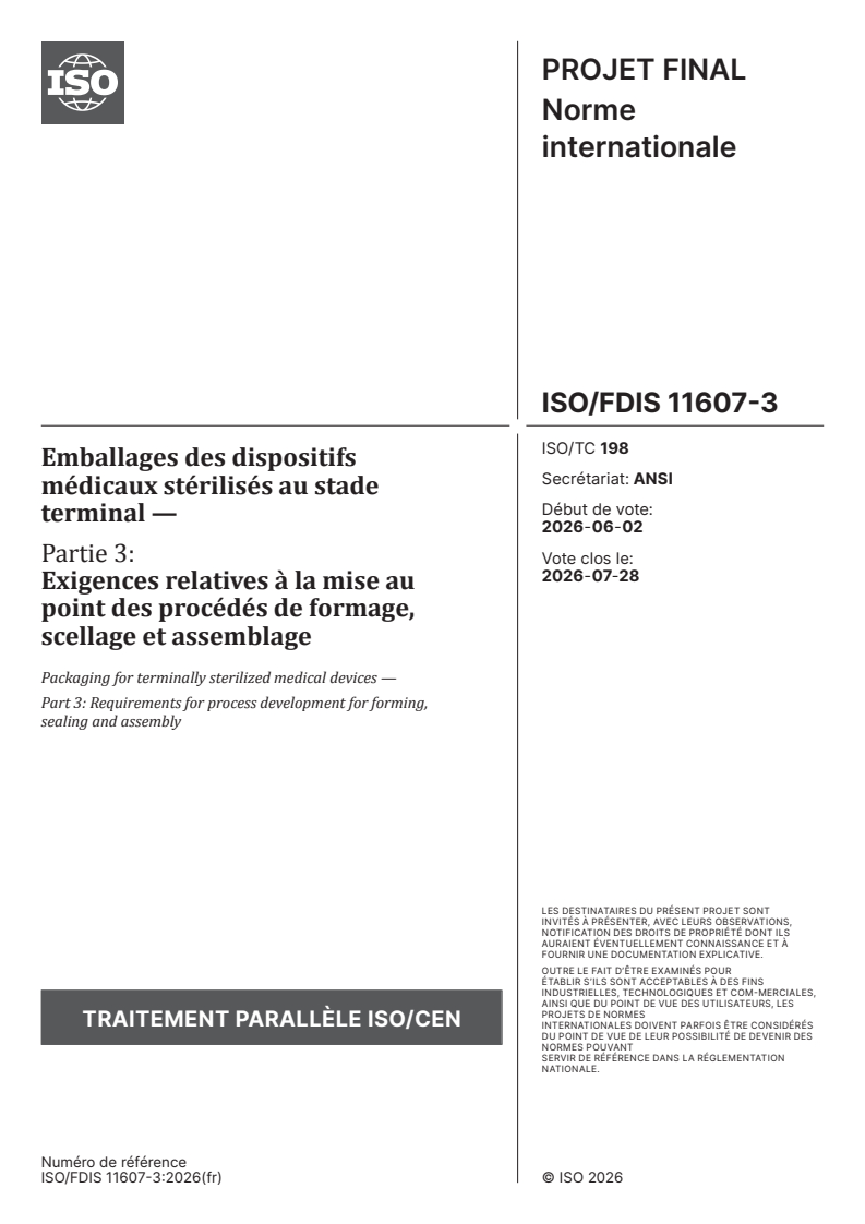

ISO/FDIS 11607-3 - Emballages des dispositifs médicaux stérilisés au stade terminal — Partie 3: Exigences relatives à la mise au point des procédés de formage, scellage et assemblage
Overview
ISO/FDIS 11607-3:2026 establishes requirements for process development related to forming, sealing, and assembly of packaging for terminally sterilized medical devices, specifically when using heat sealing technologies. Issued by the International Organization for Standardization (ISO), this standard targets both preformed sterile barrier systems (SBS) and SBSs, ensuring the integrity and sterility of medical devices up to the point of use. It builds on the sterile barrier system specification, implementing risk management principles to develop consistent, reliable processes, and identifies minimum heat sealing equipment features essential for validation, process control, and monitoring.
Key Topics
Process Development for Sealing and Assembly
- Defines step-by-step requirements for developing heat sealing processes before formal validation.
- Emphasizes iterative risk assessment and process enhancement until risk reaches an acceptable level.
Minimum Equipment Features
- Recommends essential features in heat sealing equipment to support effective process validation and monitoring.
Risk Management
- Requires integration with quality systems (e.g., ISO 9001, ISO 13485).
- Mandates risk management in line with ISO 11607-2/Amd 1:2023, including initial process risk analysis and management plans.
Process Control and Documentation
- Outlines the need for thorough documentation, including process specifications, monitoring plans, and acceptance criteria.
- Stresses the importance of establishing and documenting process variables (e.g., temperature, dwell time, contact pressure).
Process Equivalence
- Details the criteria for considering alternative heat sealing equipment or processes as equivalent, supporting change control and leveraging prior validation efforts.
Applications
ISO/FDIS 11607-3 is vital for organizations involved in the design, development, and assembly of packaging for terminally sterilized medical devices. Key applications include:
- Medical Device Manufacturers: Ensures packaging processes maintain sterile integrity through validated heat sealing methods, reducing the risk of contamination.
- Preformed Sterile Barrier System Producers: Provides a standardized framework for developing robust and consistent forming and sealing processes for commercial-scale production.
- Change Control & Process Transfer: Supports manufacturers in documenting process equivalence when introducing new or alternate sealing equipment, minimizing the need for repeated validation and testing.
- Regulated Environments: Offers guidance supporting regulatory compliance and harmonization with global standards, facilitating smooth market access and audit readiness.
- Risk Mitigation: Drives the implementation of quality and risk management systems, identifying potential process failures early to enhance patient safety.
Related Standards
Understanding and implementing ISO/FDIS 11607-3 often involves reference to other international standards in packaging and sterilization:
- ISO 11607-1: Packaging for terminally sterilized medical devices - Requirements for materials, sterile barrier systems, and packaging systems.
- ISO 11607-2: Validation requirements for forming, sealing, and assembly processes, including process specification and process validation.
- ISO 13485: Medical devices - Quality management systems - Requirements for regulatory purposes.
- ISO/TS 16775: Guidance for application of ISO 11607 (especially relevant for healthcare facilities).
- ISO 11139: Definitions of terms used in sterilization and associated equipment.
- ISO 31073: Risk management - Vocabulary.
- ASTM F1886/F1886M, ASTM F2029: Guidance for seal strength and visual inspection methods in packaging.
Summary
ISO/FDIS 11607-3:2026 provides essential guidance on developing and documenting forming, sealing, and assembly processes for sterile packaging of medical devices. By ensuring robust risk management and process control, the standard helps medical device manufacturers maintain sterility, compliance, and patient safety across evolving technologies and global markets. For organizations seeking to enhance their packaging processes, ISO/FDIS 11607-3 serves as a key resource for achieving validated, consistent, and regulatory-compliant packaging solutions.
Relations
- Effective Date
- 12-Feb-2026
- Effective Date
- 07-Jan-2025
Buy Documents
ISO/FDIS 11607-3 - Packaging for terminally sterilized medical devices — Part 3: Requirements for process development for forming, sealing and assembly
REDLINE ISO/FDIS 11607-3 - Packaging for terminally sterilized medical devices — Part 3: Requirements for process development for forming, sealing and assembly
ISO/FDIS 11607-3 - Emballages des dispositifs médicaux stérilisés au stade terminal — Partie 3: Exigences relatives à la mise au point des procédés de formage, scellage et assemblage
Get Certified
Connect with accredited certification bodies for this standard

BSI Group
BSI (British Standards Institution) is the business standards company that helps organizations make excellence a habit.

TÜV Rheinland
TÜV Rheinland is a leading international provider of technical services.

TÜV SÜD
TÜV SÜD is a trusted partner of choice for safety, security and sustainability solutions.
Sponsored listings
Frequently Asked Questions
ISO/FDIS 11607-3 is a draft published by the International Organization for Standardization (ISO). Its full title is "Packaging for terminally sterilized medical devices — Part 3: Requirements for process development for forming, sealing and assembly". This standard covers: This document specifies requirements for process development for forming, sealing and assembly of packaging for medical devices to be terminally sterilized, when utilizing heat sealing technologies. This document recommends minimum heat sealing equipment features to support subsequent validation, process control and monitoring. This document applies to both preformed sterile barrier systems and sterile barrier systems. This document utilizes the sterile barrier system specification to develop the process specification using the principles of risk management. This document is intended to be used prior to process validation. NOTE ISO 11607-2 provides requirements for process specification and process validation.
This document specifies requirements for process development for forming, sealing and assembly of packaging for medical devices to be terminally sterilized, when utilizing heat sealing technologies. This document recommends minimum heat sealing equipment features to support subsequent validation, process control and monitoring. This document applies to both preformed sterile barrier systems and sterile barrier systems. This document utilizes the sterile barrier system specification to develop the process specification using the principles of risk management. This document is intended to be used prior to process validation. NOTE ISO 11607-2 provides requirements for process specification and process validation.
ISO/FDIS 11607-3 is classified under the following ICS (International Classification for Standards) categories: 11.080.30 - Sterilized packaging. The ICS classification helps identify the subject area and facilitates finding related standards.
ISO/FDIS 11607-3 has the following relationships with other standards: It is inter standard links to FprEN ISO 11607-3, ISO 24409-4:2023. Understanding these relationships helps ensure you are using the most current and applicable version of the standard.
ISO/FDIS 11607-3 is available in PDF format for immediate download after purchase. The document can be added to your cart and obtained through the secure checkout process. Digital delivery ensures instant access to the complete standard document.
Standards Content (Sample)
FINAL DRAFT
International
Standard
ISO/TC 198
Packaging for terminally sterilized
Secretariat: ANSI
medical devices —
Voting begins on:
2026-06-02
Part 3:
Requirements for process
Voting terminates on:
2026-07-28
development for forming, sealing
and assembly
Emballages des dispositifs médicaux stérilisés au stade
terminal —
Partie 3: Exigences relatives à la mise au point des procédés de
formage, scellage et assemblage
RECIPIENTS OF THIS DRAFT ARE INVITED TO SUBMIT,
WITH THEIR COMMENTS, NOTIFICATION OF ANY
RELEVANT PATENT RIGHTS OF WHICH THEY ARE AWARE
AND TO PROVIDE SUPPOR TING DOCUMENTATION.
IN ADDITION TO THEIR EVALUATION AS
BEING ACCEPTABLE FOR INDUSTRIAL, TECHNO-
ISO/CEN PARALLEL PROCESSING LOGICAL, COMMERCIAL AND USER PURPOSES, DRAFT
INTERNATIONAL STANDARDS MAY ON OCCASION HAVE
TO BE CONSIDERED IN THE LIGHT OF THEIR POTENTIAL
TO BECOME STAN DARDS TO WHICH REFERENCE MAY BE
MADE IN NATIONAL REGULATIONS.
Reference number
FINAL DRAFT
International
Standard
ISO/TC 198
Packaging for terminally sterilized
Secretariat: ANSI
medical devices —
Voting begins on:
Part 3:
Requirements for process
Voting terminates on:
development for forming, sealing
and assembly
Emballages des dispositifs médicaux stérilisés au stade
terminal —
Partie 3: Exigences relatives à la mise au point des procédés de
formage, scellage et assemblage
RECIPIENTS OF THIS DRAFT ARE INVITED TO SUBMIT,
WITH THEIR COMMENTS, NOTIFICATION OF ANY
RELEVANT PATENT RIGHTS OF WHICH THEY ARE AWARE
AND TO PROVIDE SUPPOR TING DOCUMENTATION.
© ISO 2026
IN ADDITION TO THEIR EVALUATION AS
All rights reserved. Unless otherwise specified, or required in the context of its implementation, no part of this publication may
BEING ACCEPTABLE FOR INDUSTRIAL, TECHNO-
ISO/CEN PARALLEL PROCESSING
LOGICAL, COMMERCIAL AND USER PURPOSES, DRAFT
be reproduced or utilized otherwise in any form or by any means, electronic or mechanical, including photocopying, or posting on
INTERNATIONAL STANDARDS MAY ON OCCASION HAVE
the internet or an intranet, without prior written permission. Permission can be requested from either ISO at the address below
TO BE CONSIDERED IN THE LIGHT OF THEIR POTENTIAL
or ISO’s member body in the country of the requester.
TO BECOME STAN DARDS TO WHICH REFERENCE MAY BE
MADE IN NATIONAL REGULATIONS.
ISO copyright office
CP 401 • Ch. de Blandonnet 8
CH-1214 Vernier, Geneva
Phone: +41 22 749 01 11
Email: copyright@iso.org
Website: www.iso.org
Published in Switzerland Reference number
ii
Contents Page
Foreword .iv
Introduction .v
1 Scope . 1
2 Normative references . 1
3 Terms and definitions . 1
4 General requirements . 3
4.1 Quality systems .3
4.2 Risk management .3
4.3 Sampling .3
4.4 Test methods .3
4.5 Documentation .3
5 Process development. 3
5.1 General .3
5.2 Process development activities .4
5.3 Predetermined SBS specification(s) .5
5.4 Draft process specification . .5
5.5 Initial process risk analysis .6
5.6 Process variables .6
5.7 Initial process control and monitoring plans .7
5.8 Process specification .7
5.9 Process risk management plan .7
6 Process equivalence . 7
Annex A (informative) Guidance on establishing process parameters .10
Annex B (informative) First principles of heat sealing materials . 14
Annex C (informative) Minimum heat sealing equipment features to support subsequent
validation, process control and monitoring .18
Annex D (informative) Example of FMEA on SBS heat sealing process .22
Annex E (informative) Guidance on evaluating the equivalence of sealing outputs .24
Bibliography .27
iii
Foreword
ISO (the International Organization for Standardization) is a worldwide federation of national standards
bodies (ISO member bodies). The work of preparing International Standards is normally carried out through
ISO technical committees. Each member body interested in a subject for which a technical committee
has been established has the right to be represented on that committee. International organizations,
governmental and non-governmental, in liaison with ISO, also take part in the work. ISO collaborates closely
with the International Electrotechnical Commission (IEC) on all matters of electrotechnical standardization.
The procedures used to develop this document and those intended for its further maintenance are described
in the ISO/IEC Directives, Part 1. In particular, the different approval criteria needed for the different types
of ISO documents should be noted. This document was drafted in accordance with the editorial rules of the
ISO/IEC Directives, Part 2 (see www.iso.org/directives).
ISO draws attention to the possibility that the implementation of this document may involve the use of (a)
patent(s). ISO takes no position concerning the evidence, validity or applicability of any claimed patent
rights in respect thereof. As of the date of publication of this document, ISO had not received notice of (a)
patent(s) which may be required to implement this document. However, implementers are cautioned that
this may not represent the latest information, which may be obtained from the patent database available at
www.iso.org/patents. ISO shall not be held responsible for identifying any or all such patent rights.
Any trade name used in this document is information given for the convenience of users and does not
constitute an endorsement.
For an explanation of the voluntary nature of standards, the meaning of ISO specific terms and expressions
related to conformity assessment, as well as information about ISO’s adherence to the World Trade
Organization (WTO) principles in the Technical Barriers to Trade (TBT), see www.iso.org/iso/foreword.html.
This document was prepared by Technical Committee ISO/TC 198, Sterilization of health care products, in
collaboration with the European Committee for Standardization (CEN) Technical Committee CEN/TC 102,
Sterilizers and associated equipment for processing of medical devices, in accordance with the Agreement on
technical cooperation between ISO and CEN (Vienna Agreement).
A list of all parts in the ISO 11607 series can be found on the ISO website.
Any feedback or questions on this document should be directed to the user’s national standards body. A
complete listing of these bodies can be found at www.iso.org/members.html.
iv
Introduction
ISO 11607-1 and ISO 11607-2 specify requirements for the design and validation of sterile barrier systems for
terminally sterilized medical devices, and the validation requirements for manufacturing processes of sterile
barrier systems, respectively. The heat sealing of a sterile barrier system is critical to the maintenance of
sterile barrier integrity to the point of use; however, there is little content available for process development
in the current edition of ISO 11607-2.
This document specifies requirements for the development of heat sealing processes to meet sterile barrier
seal design requirements. A thorough development process with a high-quality output is an important
input to an efficient validation of the process. While a successful validation is essential to ensure the
safety of terminally sterilized medical devices, there is no intention to imply that the process development
approach proposed in this document is the only valid approach. Users of this document can use the activities
described in this standard to control risks associated with heat sealing processes, if they find it appropriate.
Additionally, this document specifies a process for documenting the equivalence of heat sealing processes
which can be a benefit to users in support of change control activities since it can create the basis to leverage
the efforts over a range of heat sealing equipment or over a sterile barrier system family.
This document is intended for use by industrial manufacturers engaged in the design and development of
sterile barrier systems and heat sealing processes. Effective application of the requirements described in
this document requires proficiency in design of experiment (DOE) methodologies and access to the requisite
testing resources for result evaluation. Producers of preformed sterile barrier systems, as well as medical
device manufacturers, rely heavily on heat sealing, among other techniques, to create sterile barrier
systems that ensure device integrity and sterility at various stages of distribution and handling of sterile
devices until the point of use and aseptic presentation. This process often involves the operation of multiple,
interchangeable heat sealers to produce commercial quantities of sterile barrier systems.
For healthcare facilities (e.g. hospitals), ISO/TS 16775:2021, Annex B contains all relevant guidance for
sterile barrier system closure technologies including sealing, reusable container closures and wrapping
processes.
v
FINAL DRAFT International Standard ISO/FDIS 11607-3:2026(en)
Packaging for terminally sterilized medical devices —
Part 3:
Requirements for process development for forming, sealing
and assembly
1 Scope
This document specifies requirements for process development for forming, sealing and assembly of
packaging for medical devices to be terminally sterilized, when utilizing heat sealing technologies.
This document recommends minimum heat sealing equipment features to support subsequent validation,
process control and monitoring.
This document applies to both preformed sterile barrier systems and sterile barrier systems.
This document utilizes the sterile barrier system specification to develop the process specification using the
principles of risk management.
This document is intended to be used prior to process validation.
NOTE ISO 11607-2 provides requirements for process specification and process validation.
2 Normative references
The following documents are referred to in the text in such a way that some or all of their content constitutes
requirements of this document. For dated references, only the edition cited applies. For undated references,
the latest edition of the referenced document (including any amendments) applies.
ISO 11607-2:2019, Packaging for terminally sterilized medical devices — Part 2: Validation requirements for
forming, sealing and assembly processes
ISO 11607-2:2019/Amd 1:2023, Packaging for terminally sterilized medical devices — Part 2: Validation
requirements for forming, sealing and assembly processes — Amendment 1: Application of risk management
3 Terms and definitions
For the purposes of this document, the following terms and definitions apply.
ISO and IEC maintain terminology databases for use in standardization at the following addresses:
— ISO Online browsing platform: available at https:// www .iso .org/ obp
— IEC Electropedia: available at https:// www .electropedia .org/
3.1
assembly
process of putting together all components of a sterile barrier system, including packaging
materials and contents
3.2
control
regulation of variables within specified limits
[SOURCE: ISO 11139:2018, 3.63]
3.3
forming
process of bringing materials into contact with each other or into the necessary position for
heat sealing or closure processes to create a sterile barrier system
Note 1 to entry: Forming in this context does not include thermoforming, cold-forming, forming thermoform portion
of form-fill-seal, fabrication of the material.
3.4
monitoring
continual checking, supervising, critically observing or determining the status in order to identify change
from the performance level required or expected
[SOURCE: ISO 31073:2022, 3.3.40, modified — Note to entry has been deleted.]
3.5
process parameter
specified value for a process variable
Note 1 to entry: The specification for a process includes the process parameters and their tolerances.
[SOURCE: ISO 11139:2018, 3.211]
3.6
process specification
documented procedure that includes all equipment, process parameters, monitors and materials required
to manufacture a product that consistently meets requirements
[SOURCE: ISO 11607-2:2019, 3.15]
3.7
process variable
chemical or physical attribute within a cleaning, disinfection, packaging or sterilization process, changes in
which can alter its effectiveness
EXAMPLE Time, temperature, pressure, concentration, humidity, wavelength.
[SOURCE: ISO 11139:2018, 3.213]
3.8
seal
result of joining surfaces together by fusion to form a microbial barrier
Note 1 to entry: For sealing by thermal fusion, this can include multiple heat sealing equipment technologies, but not
cold sealing.
[SOURCE: ISO 11139:2018, 3.244, modified — Note 1 to entry has been added.]
3.9
sterile barrier system
SBS
minimum package that minimizes the risk of ingress of microorganisms and allows aseptic presentation of
the sterile contents at the point of use
[SOURCE: ISO 11139:2018, 3.272]
4 General requirements
4.1 Quality systems
The activities described within this document shall be carried out within a formal quality system.
NOTE ISO 9001 and ISO 13485 contain requirements for suitable quality systems. Additional requirements can
be specified by a country or region.
4.2 Risk management
A risk management process conforming with the requirements of ISO 11607-2/Amd 1:2023 shall be
implemented.
4.3 Sampling
Sampling plans based upon a statistically valid rationale is required for validation per ISO 11607-2.
Application of statistical aspects for sampling plans used in development of heat sealing processes is helpful.
This can include a rationale on statistical aspects regarding the materials, risks and sterile barrier systems
being evaluated.
NOTE Statistically valid indicates the use of a methodology that ensures the sample size and selection process are
appropriate for drawing reliable and accurate conclusions.
4.4 Test methods
Test methods used for activities described in this document shall meet the test method validation
requirements of ISO 11607-2. Process development may include preliminary evaluation methods which do
not require validation.
NOTE Preliminary evaluation methods focus on understanding the characteristics, attributes, or qualities of a
product or process (e.g. visual scoring method for heat seals which includes estimating attributes of a heat seal). See
Annex A, particularly A.2.4.
4.5 Documentation
Documentation of activities described in this document shall meet the documentation requirements of
ISO 11607-2:2019, 4.5.
5 Process development
5.1 General
5.1.1 The requirements of this document are intended to be applied to heat sealing processes that have
not yet been validated. Existing SBS and preformed SBS heat sealing processes that have successfully
met the validation requirements of ISO 11607-2 may be regarded as sufficient evidence that appropriate
process development has occurred; therefore, no additional process development activities according to this
document shall be required.
NOTE 1 The heat sealing processes of interest are those for SBS seals that establish a microbial barrier. Other types
of seals, such as those used for containment or spot welds for wraps bonding, are not used to create a microbial barrier
and are not covered in this document.
NOTE 2 This document provides an approach that meets the process development requirements for consistency;
however, there can be other valid approaches.
5.1.2 When process development is conducted prior to installation qualification (IQ), a documented
rationale should assess any risk with production equivalence and impact to process input and design output.
5.2 Process development activities
The process development activities as illustrated in Figure 1 shall be followed in an iterative way (not
linearly) until the objective is achieved. Process development concludes when an acceptable level of risk
has been achieved prior to proceeding to process validation. If the risk is not yet acceptable, the process
development activities shall be reviewed and improved until the risk level is acceptable.
NOTE Additional detailed information for each step of the process is provided in 5.3 through 5.9.
Figure 1 — Process development activities
5.3 Predetermined SBS specification(s)
5.3.1 Process development shall be based on predetermined SBS specification requirements:
a) SBS forming and assembly requirements (e.g. top/bottom web overlap, free from wrinkles or creases
that can impact seal quality, sequence of assembly operations);
b) SBS seal requirements (e.g. seal width, seal strength);
c) packaging materials (e.g. trays, lids, preformed SBS, roll stock, retainers to keep product in place);
d) SBS contents (if applicable).
NOTE Annex B provides information on heat sealing materials to assist process development.
5.3.2 Process development may be leveraged across families of similar SBSs, SBS specifications, or process
specifications. The rationale for such families shall be documented.
5.4 Draft process specification
5.4.1 Process elements and production provisions required to achieve process outputs shall be identified.
NOTE In this document, production provisions refer to the surrounding conditions and supporting arrangements
necessary to consistently achieve the specified process outputs.
5.4.1.1 Process elements can include but are not limited to:
a) equipment [e.g. heat sealer, form-fill-seal (FFS) machine];
b) equipment accessories (e.g. heating plates, tooling, fixtures, gaskets, product positioning guides);
c) measurement (e.g. test equipment, gauges);
d) workflow equipment (e.g. conveyors, tables, bins, verification device to confirm material is correct);
e) process consumables (e.g. seal jaw tape, mats, web cleaners).
5.4.1.2 Production provisions can include, but are not limited to:
a) environmental conditions (e.g. temperature, humidity, cleanroom requirements, inspection lighting);
b) utilities (e.g. compressed air, electrical supply);
c) process for using cleaning agents, disinfectants;
d) procedures for installation, operation, and maintenance of equipment if available;
e) personal protective equipment (e.g. gloves, cleanroom gowns);
f) personnel.
NOTE 1 A well-developed heat sealing process window is essential. However, SBS integrity issues can be caused by
the elements and provisions surrounding the heat sealing process.
NOTE 2 Annex C provides guidance on equipment features to enable process validation, monitoring, and control.
5.4.2 Process outputs and acceptance criteria based on predetermined SBS specifications shall be
documented in the process specification.
5.5 Initial process risk analysis
5.5.1 An initial process risk analysis shall be performed to identify potential process failure modes that
prevent the process outputs from meeting predetermined SBS specifications. Performing initial risk analysis
can facilitate accomplishment of the Process Risk Management Plan in 5.9 of this document.
NOTE Risk analysis tools can aid in the establishment of input and output relationships during process
development, see Annex D for an example of a failure modes and effects analysis (FMEA) for an SBS heat sealing
process.
Example failure modes include, but are not limited to:
a) seal strength out of specification (e.g. weak or strong seal);
b) narrow seal (e.g. voids within the seal area, seal not meeting dimensional specification);
c) channels or open seals;
d) damaged SBS materials (e.g. punctures, tears, excessive melting, deformation);
e) unintended material delamination for seals designed to be opened by peeling;
f) any known risk from previous validations if using an existing process.
5.5.2 A previously documented process risk analysis can be leveraged; in this case an initial risk analysis
according to 5.5 may be omitted.
NOTE 1 ISO 11607-2:2019/Amd 1:2023, Table B.1 includes possible contributing factors of process provisions that
can result in a hazardous situation.
NOTE 2 Labelling can be considered if it creates a risk to the sealing process. Otherwise it is not in scope of this
document.
5.5.3 Initial process risk analysis shall identify process related causes of failure modes for all process
elements and production provisions in 5.4.1.
Example causes include, but are not limited to:
a) contamination of seal tool or seal bar (e.g. debris, lack of cleanliness);
b) contamination of SBS material (e.g. residues of cleaning agents, contaminated gloves);
c) incorrect sealing equipment output (e.g. wrong parameter setting, calibration offset issue, pneumatic
loss, poor heat distribution);
d) damaged process elements (e.g. seal bar, gasket, improper maintenance);
e) incorrect tool or equipment accessory (e.g. alignment guide);
f) incorrect set up (e.g. web tension, web alignment, web position, poor line clearance).
5.5.4 Initial process risk analysis shall identify process variables and the controls or monitoring of those
variables that can be required to mitigate process related failure modes.
5.6 Process variables
5.6.1 The process variables required to achieve the required process outputs shall be identified.
Examples of process variables can include, but are not limited to:
a) temperature;
b) contact pressure;
c) dwell time or line speed.
NOTE Process time between heat seal cycles can affect the process output.
5.6.2 Process variables shall be evaluated by:
a) determining the effect of the identified process variables on the process outputs;
NOTE Design of experiments (DOE) is an approach often used to efficiently study process variables. Further
guidance can be found in Annex A.
b) determining the upper and lower limits of process variables that produce the required process outputs.
NOTE Some materials have a wide process window which produces the desired process outputs, making it of
little added value to determine the absolute upper and lower limits.
5.6.3 Process parameters to be used in process validation activities shall be determined.
5.7 Initial process control and monitoring plans
5.7.1 Process parameters required to consistently meet required process outputs shall be documented, as
well as the means of monitoring or controlling as appropriate.
NOTE Heat sealing equipment can include systems to set, control or monitor process variables. Systems can
include alarms, warnings or machine stops in the event a process variable exceeds limits.
5.7.2 Process outputs to be monitored including the frequency of monitoring, sample size, test method,
acceptance criteria and reaction plans shall be documented.
NOTE A control plan is an example of an approach that can be used to define how process outputs and variables
are monitored.
5.8 Process specification
The process specification shall be established based on the outputs of the activities completed in 5.4 through
5.7, meeting the requirements of ISO 11607-2.
NOTE 1 ISO 11607-2 includes requirements for the process specification to be documented as an output of process
development, traceable to the predetermined design specification and as the basis for process validation.
NOTE 2 The process specification can be a document or series of documents.
5.9 Process risk management plan
The output of process development activities supports the risk management plan.
NOTE ISO 11607-2:2019/Amd 1:2023, Annex B contains requirements for sterile barrier system process risk
management. ISO 11607-2/Amd 1:2023 includes the permission to combine risk management plans and related
records and documentation for forming, sealing and assembly of sterile barrier systems with those for the medical
device.
6 Process equivalence
6.1 Processes run on alternate sealing equipment may be considered equivalent if all requirements below
(as illustrated in Figure 2) are met:
NOTE 1 The term “alternate” is intended to cover multiple scenarios for deploying sealing equipment at a
manufacturing location including, but not limited, to new machines, used machines, refurbished machines, or machines
that have been moved to a new location that can affect machine output, such as a geography with a different electrical
power system.
a) SBS specification requirements shall be the same.
b) Alternate heat sealing equipment shall be based on equivalent heat sealing technology. The heat sealing
technology may be considered equivalent when it is within the same category (e.g. constant heat bar
sealer, rotary sealer, blister tray sealer), regardless of model or manufacturer.
NOTE 2 Relevant tolerances of process variables of alternate heat sealing equipment are an important
consideration in the assessment of equivalence. Equivalent process variables can have a bias in settings due to
temperature measurement, dwell time or pressure output as documented in equipment calibration, see Annex C.
This can result in different settings on alternate equipment to run the equivalent process.
c) Alternate heat sealing equipment shall use equivalent process elements.
d) Alternate heat sealing equipment shall not introduce any new, different, unique or increased risks
related to heat sealing which would require new risk controls or risk management plan.
e) Process outputs on alternate equipment shall meet SBS specifications.
NOTE 3 Statistical analysis of process outputs can be used to support process equivalence to leverage prior SBS
testing. Guidance on statistical equivalence evaluation is contained in Annex E.
6.2 In case of documented process equivalence based on 6.1, previous process development may be
leveraged. Validation activities on the alternate equipment shall meet the requirements of ISO 11607-2 in
alignment with change controls.
6.3 For processes documented as equivalent, previous testing activities such as those that demonstrate
conformity to ISO 11607-1:2019, Clause 8 are not impacted and may be considered as still valid.
NOTE 1 It is possible that alternate heat sealing equipment can require modifications or adjustments to process
variables or settings to achieve the same sealing energy. However, the focus of the equivalency assessment is on the
ability of the sealing process output to meet the SBS specification.
NOTE 2 ISO 11607-1 contains requirements for change management and revalidation if changes are made to the
design, contents, packaging materials, or configurations that compromise the original validation and can affect the
integrity of the sterile barrier system.
Figure 2 — Equivalence decision tree
Annex A
(informative)
Guidance on establishing process parameters
A.1 General
This annex is applicable to industrial manufacturers of both preformed SBSs and SBSs.
Process parameters, including ranges and tolerances, are necessary to ensure that a product satisfies the
defined requirements under all the anticipated conditions of manufacturing. These parameters should be
established using statistically valid techniques. Examples of approaches that can be used include:
— design of experiments (DOE);
— heat seal curve analysis;
— scoring of visual attributes of heat seals.
A.2 Example of forming and sealing an SBS (lidded tray)
A.2.1 Design of experiments (DOE)
Design of experiments is used to optimize the process parameter window and identify the process conditions
that will ensure that good quality product is consistently produced. The more detailed information obtained
at this stage, the easier it is to maintain control of the process. DOE activities can start with process
characterization to identify key process inputs that influence process outputs prior to full DOE.
Heat sealing a lid to a formed tray requires consideration of temperature, pressure, and dwell time. The DOE
activity should identify the range of process conditions that will have the minimum effect on the resulting
SBS.
For example, the process conditions necessary to ensure an acceptable seal when heat sealing the lid should:
— be sufficiently removed from those process conditions which will result in failure of the seal;
— produce a seal meeting specifications;
— show acceptable variation in seal strength.
Various levels of experiments can be conducted which could be simple, linear screening studies (sometimes
referred to as process characterization) to determine the relative effect of various parameters on the
resulting seal or highly complex, fractional factorial quadratic studies. Often a simple, linear experiment
is conducted to confirm the significance of parameters, potentially followed by a more complex study with
centre points to ensure a good mathematical model of the process is generated which fits the data. It is often
found that temperature is the most important variable, followed by time and then pressure.
The approaches used to establish the optimum conditions for heat seals are:
— heat seal curve analysis;
— scoring of visual attributes of heat seals;
— a combination of the heat seal curve analysis and scoring of visual attributes;
— initial analysis of process variability in support of process capability;
— evaluation of seal integrity.
NOTE For information on visual inspection of seals, see ASTM F1886/F1886M.
A.2.2 Heat seal curve analysis (process range assessment)
This procedure involves evaluating how a matrix of temperature, pressure and dwell time will impact
the material characteristics for seal strength. Curves constructed to determine the effects of the various
parameters normally show that varying pressure and dwell time have less of an effect on seal strength,
so these are kept constant while the temperature is varied. The heat seal curve analysis can support the
development of process limits over the range where the seal strength meets specification. These limits should
be established in a way that seal strength is maintained and other visually undesirable seal characteristics
are minimized (see Figure A.1, Tables A.1 and A.2). For additional details on how to create heat seal curves,
see ASTM F2029.
NOTE 1 Depending on the type of equipment, temperature and time are inversely correlated. Pressure is also
important but often fixed. Sealants and heat seal coatings will soften or melt at a certain temperature. At temperatures
above that softening or melting point, higher temperature settings can enable shorter dwell times, while longer
dwell times can be needed at lower temperature settings. Sealant squeeze out can be the result of applying too much
pressure.
NOTE 2 Heat seal curve analysis is often performed on a calibrated sealing device, with a precise adjustment,
control and monitoring of process parameters. Settings illustrated on heat seal curves obtained on a lab sealing device
can be different from settings on production equipment.
Key
X temperature
Y seal strength
1 proposed process limits
Figure A.1 — Heat seal curve for optimum process parameters
A.2.3 Visual scoring method for heat seals
Seals should be scored for visual observations and defects at both ends of the process range. Higher scores
indicate better quality. Specific acceptance criteria for visual scoring should be established. The following
tables provide visual scoring examples:
a) lower end of heat sealing range (see Table A.1);
Table A.1 — Lower end of sealing range
Score Visual seal observations
0 Open seals
Spotty or nonhomogeneous seals resulting in seal width less than 50 % of the specified value (spotty
appearance caused by incomplete softening or melting of the sealant material)
2 Spotty or nonhomogeneous seals resulting in seal width between 50 % and 74 % of the specified value
3 Spotty or nonhomogeneous seals resulting in seal width between 75 % and 94 % of the specified value
4 Seal width >95 % of the specified value with sporadic spotty or nonhomogeneous spots
5 Full intended seal (>95 % of the specified value), fully continuous and homogenous
b) upper end of heat sealing range (see Table A.2).
Table A.2 — Upper end of sealing range
Score Visual seal observations
0 Holes in materials
Welded seals or melted polymer
Severe curl of the flange of the tray
Severe transparentization of polymer based nonwoven lids
Severe fibre tearing of paper-based lids
Moderate curl of the flange of the tray
2 Moderate transparentization of polymer based nonwoven lids
Significant fibre tear of paper-based lids
Mottled (also spotty appearance but due to overactivation of the material) seals
3 Minor transparentization of polymer based nonwoven lids
Moderate fibre tearing of paper-based lids
Slight curl of the flange of the tray
Slight transparentization of polymer based nonwoven lids
Occasional mottling
Slight fibre tearing of paper-based lids
5 Good quality seals
A.2.4 Combining heat seal curve analysis and visual scoring
The results obtained from the analysis of heat seals can be combined with those obtained using the visual
scoring method to produce a graph as represented in Figure A.2.
Key
X temperature
Y1 seal strength
Y2 visual seal quality
1 proposed process limits
2 specification limits
Figure A.2 — Seal strength and visual seal quality vs. temperature
Annex B
(informative)
First principles of heat sealing materials
B.1 General
Heat sealing is a critical process in the forming of a sterile barrier system. The process joins one flexible SBS
material to another, or a flexible SBS material to a rigid SBS material. A basic discussion of SBS materials
is presented to provide a general understanding of the function of materials used to create seals. This
information is intended to add value to the development of heat sealing processes.
B.2 Fundamentals of heat-seal materials
B.2.1 General
There are two main ways for creating a sealable surface on an SBS material: films with sealant layers and
heat seal coatings.
B.2.2 Sealant films
Film sealant layers are used extensively in the creation of both peelable and weld seals. In most cases,
the nonporous film used to create a SBS is a multilayer structure comprising two or more layers that are
combined by coextrusion, adhesive lamination, extrusion coating or extrusion lamination. Multilayer films
offer many advantages for creating a robust SBS. One layer of the film can be used to provide mechanical
strength to the film while another layer is used to enhance barrier properties. The inner layer (product
facing) of such a composite film is the heat seal layer.
For peelable seals, the sealant layer includes a mixture of two polymers, a base sealant polymer and a second
immiscible polymer. The base sealant polymer creates the seal while the second polymer is used to control
the point of fracture, or controlled point of failure when the SBS is peeled open. This formulation of the
second polymer is what drives the cohesive strength.
Some film sealant layers are designed and formulated to create a weld seal, or a non-peelable seal. A non-
peelable seal is not intended to be opened by the end user.
B.2.3 Heat seal coatings or treatments
Heat seal coatings or treatments are thermoplastic, polymer-based materials that can be applied to porous
and nonporous substrates and are designed to adhere to and peel cleanly from common materials of
construction for SBS packaging. The interface between a heat seal coating or treatment and the SBS web
materials will be a sharp interface in most cases.
During heat sealing the coating or treatment is heated and melted to fully wet the companion web surface
to create a seal with integrity. The adhesive strength is dependent on intermolecular forces, or the chemical
similarity that makes the materials attracted to one another resulting in the adhesive force being greater
than the cohesive force or strength of the adhesive material. The cohesive force or strength is designed to be
the weak point of the SBS seal ensuring peelability without creating particulate upon opening.
Porous web surface treatment is a technology where the heat seal adhesive is applied simultaneously during
the creation of the breathable webs using specialized surface treatment machinery, rather than being
applied offline as a layer coating after the breathable web manufacturing process.
NOTE See also EN 868-7 and EN 868-10 for coated material applications.
The adhesive weight can influence the cohesive or adhesive failure modes of the seal during peeling, which
can affect the consistency of seal strength and the coating transfer appearance between two substrates.
B.3 Fundamentals of heat sealing
B.3.1 General
Heat sealing creates a bond between two materials through melting of the polymers at the seal interface,
polymer chain entanglement at the interface, and through chemical attractions. As a rule, polymers of
similar chemistry are required to create good heat seals. For example, low-density polyethylene (LDPE)
will seal well to other polyethylene materials, but not to polypropylene. In typical SBS applications, thermal
energy (heat) is used to initiate and complete the heat seal. In many cases, the webs that are sealed together
are multi-layer structures such as laminated films or coextruded films. An example of two webs before and
after sealing is shown in Figure B.1.
Key
seal interface
Figure B.1 — Unsealed and sealed structures (not to scale)
B.3.2 Molecular attraction
Adhesive force is a function of molecular attraction that acts between the heat seal coating or sealant and
the adherend material. There are several mechanisms available to create this force, primarily this adhesive
force is driven by chemical similarity of the materials. The materials of the of heat seal coating or sealant and
the adherends, when in very close proximity, will create intermolecular forces which hold the two materials
together at the interface. During heat sealing, the seal created will have a diffuse interface, a sharp interface
or a mechanical bond.
B.3.3 Interface
For the development of heat sealing processes, an understandi
...
ISO/TC 198/WG 7
Secretariat: ANSI
Date: 2026-04-2105-18
Packaging for terminally sterilized medical devices — —
Part 3:
Requirements for process development for forming, sealing and
assembly
Emballages des dispositifs médicaux stérilisés au stade terminal —
Partie 3: Exigences relatives à la mise au point des procédés de formage, scellage et assemblage
FDIS stage
TTTTThThhhhhiiiiiiss drs drs drs drs dr draaaaaafffffftttttt i i i i i is s s s s s susususususubbbbbbmmmmmmiiiiiitttttttttttteeeeeed d d d d d ttttttoooooo aaaaaa ppppppaaaaaarrrrrraaaaaallellellellellellel l l l ll vvvvvvooooootttttteeeeee i i i iininnnnn IIIIIISSSSSSOOOOOO,,,,,, CCCCCCEEEEEEN.N.N.N.NN.
ISO/DIS FDIS 11607-3:20252026(en)
All rights reserved. Unless otherwise specified, or required in the context of its implementation, no part of this publication
may be reproduced or utilized otherwise in any form or by any means, electronic or mechanical, including photocopying,
or posting on the internet or an intranet, without prior written permission. Permission can be requested from either ISO
at the address below or ISO’s member body in the country of the requester.
ISO copyright office
CP 401 • Ch. de Blandonnet 8
CH-1214 Vernier, Geneva
Phone: + 41 22 749 01 11
EmailE-mail: copyright@iso.org
Website: www.iso.org
Published in Switzerland
ii
Contents
Foreword . iv
Introduction . v
1 Scope . 1
2 Normative references . 1
3 Terms and definitions . 1
4 General requirements . 3
4.1 Quality systems . 3
4.2 Risk management . 3
4.3 Sampling . 3
4.4 Test methods . 3
4.5 Documentation . 3
5 Process development . 3
5.1 General . 3
5.2 Process development activities . 4
5.3 Predetermined SBS specification(s) . 5
5.4 Draft process specification . 6
5.5 Initial process risk analysis . 7
5.6 Process variables . 7
5.7 Initial process control and monitoring plans . 8
5.8 Process specification . 8
5.9 Process risk management plan . 8
6 Process equivalence . 9
Annex A (informative) Guidance on establishing process parameters . 11
Annex B (informative) First principles of heat sealing materials . 15
Annex C (informative) Minimum heat sealing equipment features to support subsequent
validation, process control and monitoring . 19
Annex D (informative) Example of FMEA on SBS heat sealing process . 24
Annex E (informative) Guidance on evaluating the equivalence of sealing outputs . 26
Bibliography . 29
iii
ISO/DIS FDIS 11607-3:20252026(en)
Foreword
ISO (the International Organization for Standardization) is a worldwide federation of national standards
bodies (ISO member bodies). The work of preparing International Standards is normally carried out through
ISO technical committees. Each member body interested in a subject for which a technical committee has been
established has the right to be represented on that committee. International organizations, governmental and
non-governmental, in liaison with ISO, also take part in the work. ISO collaborates closely with the
International Electrotechnical Commission (IEC) on all matters of electrotechnical standardization.
The procedures used to develop this document and those intended for its further maintenance are described
in the ISO/IEC Directives, Part 1. In particular, the different approval criteria needed for the different types of
ISO documents should be noted. This document was drafted in accordance with the editorial rules of the
ISO/IEC Directives, Part 2 (see www.iso.org/directives).
ISO draws attention to the possibility that the implementation of this document may involve the use of (a)
patent(s). ISO takes no position concerning the evidence, validity or applicability of any claimed patent rights
in respect thereof. As of the date of publication of this document, ISO had not received notice of (a) patent(s)
which may be required to implement this document. However, implementers are cautioned that this may not
represent the latest information, which may be obtained from the patent database available at
www.iso.org/patents. ISO shall not be held responsible for identifying any or all such patent rights.
Any trade name used in this document is information given for the convenience of users and does not
constitute an endorsement.
For an explanation of the voluntary nature of standards, the meaning of ISO specific terms and expressions
related to conformity assessment, as well as information about ISO'sISO’s adherence to the World Trade
Organization (WTO) principles in the Technical Barriers to Trade (TBT), see www.iso.org/iso/foreword.html.
This document was prepared by Technical Committee ISO/TC 198, Sterilization of health care products, in
collaboration with the European Committee for Standardization (CEN) Technical Committee CEN/TC 102,
Sterilizers and associated equipment for processing of medical devices, in accordance with the Agreement on
technical cooperation between ISO and CEN (Vienna Agreement).
A list of all parts in the ISO 11607 series can be found on the ISO website.
Any feedback or questions on this document should be directed to the user’s national standards body. A
complete listing of these bodies can be found at www.iso.org/members.html.
iv
Introduction
ISO 11607-1 and ISO 11607-2 specify requirements for the design and validation of sterile barrier systems for
terminally sterilized medical devices, and the validation requirements for manufacturing processes of sterile
barrier systems, respectively. The heat sealing of a sterile barrier system is critical to the maintenance of
sterile barrier integrity to the point of use; however, there is little content available for process development
in the current edition of ISO 11607-2.
This document specifies requirements for the development of heat sealing processes to meet sterile barrier
seal design requirements. A thorough development process with a high-quality output is an important input
to an efficient validation of the process. While a successful validation is essential to ensure the safety of
terminally sterilized medical devices, there is no intention to imply that the process development approach
proposed in this document is the only valid approach. Users of this document can use the activities described
in this standard to control risks associated with heat sealing processes, if they find it appropriate. Additionally,
this document specifies a process for documenting the equivalence of heat sealing processes which can be a
benefit to users in support of change control activities since it can create the basis to leverage the efforts over
a range of heat sealing equipment or over a sterile barrier system family.
This document is intended for use by industrial manufacturers engaged in the design and development of
sterile barrier systems and heat sealing processes. Effective application of the requirements described in this
document requires proficiency in design of experiment (DOE) methodologies and access to the requisite
testing resources for result evaluation. Producers of preformed sterile barrier systems, as well as medical
device manufacturers, rely heavily on heat sealing, among other techniques, to create sterile barrier systems
that ensure device integrity and sterility at various stages of distribution and handling of sterile devices until
the point of use and aseptic presentation. This process often involves the operation of multiple,
interchangeable heat sealers to produce commercial quantities of sterile barrier systems.
For healthcare facilities (e.g. hospitals), ISO/TS 16775:2021, Annex B contains all relevant guidance for sterile
barrier system closure technologies including sealing, reusable container closures and wrapping processes.
v
FINAL DRAFT International Standard ISO/FDIS 11607-3:2026(en)
Packaging for terminally sterilized medical devices —
Part 3:
Requirements for process development for forming, sealing and
assembly
1 Scope
This document specifies requirements for process development for forming, sealing and assembly of
packaging for medical devices to be terminally sterilized, when utilizing heat sealing technologies.
This document recommends minimum heat sealing equipment features to support subsequent validation,
process control and monitoring.
This document applies to both preformed sterile barrier systems and sterile barrier systems.
This document utilizes the sterile barrier system specification to develop the process specification using the
principles of risk management.
This document is intended to be used prior to process validation.
NOTE ISO 11607-2 provides requirements for process specification and process validation.
2 Normative references
The following documents are referred to in the text in such a way that some or all of their content constitutes
requirements of this document. For dated references, only the edition cited applies. For undated references,
the latest edition of the referenced document (including any amendments) applies.
ISO 11607-2:2019 & Amd -2:2019, Packaging for terminally sterilized medical devices — Part 2: Validation
requirements for forming, sealing and assembly processes
ISO 11607-2:2019/Amd 1:2023, Packaging for terminally sterilized medical devices — Part 2: Validation
requirements for forming, sealing and assembly processes & — Amendment 1: Application of Risk
Managementrisk management
3 Terms and definitions
For the purposes of this document, the following terms and definitions apply.
ISO and IEC maintain terminology databases for use in standardization at the following addresses:
— — ISO Online browsing platform: available at https://www.iso.org/obp
— — IEC Electropedia: available at https://www.electropedia.org/
3.1 3.1
assembly
process of putting together all components of a sterile barrier system, including packaging
materials and contents
3.2 3.2
control
regulation of variables within specified limits
[SOURCE: ISO 11139:2018, 3.63]
3.3 3.3
forming
process of bringing materials into contact with each other or into the necessary position for heat
sealing or closure processes to create a sterile barrier system
Note 1 to entry: Forming in this context does not include thermoforming, cold-forming, forming thermoform portion of
form-fill-seal, fabrication of the material.
3.4 3.4
monitoring
continual checking, supervising, critically observing or determining the status in order to identify change from
the performance level required or expected
[SOURCE: ISO 31073:2022, 3.3.40, modified — Note to entry has been deleted.]
3.5 3.5
process parameter
specified value for a process variable
Note 1 to entry: The specification for a process includes the process parameters and their tolerances.
[SOURCE: ISO 11139:2018, 3.211]
3.6 3.6
process specification
documented procedure that includes all equipment, process parameters, monitors and materials required to
manufacture a product that consistently meets requirements
[SOURCE: ISO 11607-2:2019, 3.15]
3.7 3.7
process variable
chemical or physical attribute within a cleaning, disinfection, packaging or sterilization process, changes in
which can alter its effectiveness
EXAMPLE Time, temperature, pressure, concentration, humidity, wavelength.
[SOURCE: ISO 11139:2018, 3.213]
3.8 3.8
seal
result of joining surfaces together by fusion to form a microbial barrier
Note 1 to entry: For sealing by thermal fusion, this can include multiple heat sealing equipment technologies, but not cold
sealing.
[SOURCE: ISO 11139:2018, 3.244, modified — Note 1 to entry has been added.]
3.9 3.9
sterile barrier system
SBS
minimum package that minimizes the risk of ingress of microorganisms and allows aseptic presentation of the
sterile contents at the point of use
[SOURCE: ISO 11139:2018, 3.272]
4 General requirements
4.1 Quality systems
The activities described within this document shall be carried out within a formal quality system.
NOTE ISO 9001 and ISO 13485 contain requirements for suitable quality systems. Additional requirements can be
specified by a country or region.
4.2 Risk management
A risk management process conforming with the requirements of ISO 11607-2/Amd 1:2023 shall be
implemented.
4.3 Sampling
Sampling plans based upon a statistically valid rationale is required for validation per ISO 11607-2.
Application of statistical aspects for sampling plans used in development of heat sealing processes is helpful.
This can include a rationale on statistical aspects regarding the materials, risks and sterile barrier systems
being evaluated.
NOTE Statistically valid indicates the use of a methodology that ensures the sample size and selection process are
appropriate for drawing reliable and accurate conclusions.
4.4 Test methods
Test methods used for activities described in this document shall meet the test method validation
requirements of ISO 11607-2. Process development may include preliminary evaluation methods which do
not require validation.
NOTE Preliminary evaluation methods focus on understanding the characteristics, attributes, or qualities of a
product or process (e.g. visual scoring method for heat seals which includes estimating attributes of a heat seal). See
Annex AAnnex A,, particularly A.2.4A.2.4.
4.5 Documentation
Documentation of activities described in this document shall meet the documentation requirements of
ISO 11607-2:2019, 4.5.
5 Process development
5.1 General
5.1.1 5.1.1 The requirements of this document are intended to be applied to heat sealing processes that
have not yet been validated. Existing SBS and preformed SBS heat sealing processes that have successfully met
the validation requirements of ISO 11607-2 may be regarded as sufficient evidence that appropriate process
development has occurred; therefore, no additional process development activities according to this
document shall be required.
NOTE 1 The heat sealing processes of interest are those for SBS seals that establish a microbial barrier. Other types of
seals, such as those used for containment or spot welds for wraps bonding, are not used to create a microbial barrier and
are not covered in this document.
NOTE 2 This document provides an approach that meets the process development requirements for consistency;
however, there can be other valid approaches.
5.1.2 5.1.2 When process development is conducted prior to installation qualification (IQ), a documented
rationale should assess any risk with production equivalence and impact to process input and design output.
5.2 Process development activities
The process development activities as illustrated in Figure 1Figure 1 shall be followed in an iterative way (not
linearly) until the objective is achieved. Process development concludes when an acceptable level of risk has
been achieved prior to proceeding to process validation. If the risk is not yet acceptable, the process
development activities shall be reviewed and improved until the risk level is acceptable.
NOTE Additional detailed information for each step of the process is provided in 5.35.3 through 5.95.9.
Figure 1 — Process development activities
5.3 Predetermined SBS specification(s)
5.3.1 5.3.1 Process development shall be based on predetermined SBS specification requirements:
a) a) SBS forming and assembly requirements (e.g. top/bottom web overlap, free from wrinkles or
creases that can impact seal quality, sequence of assembly operations);
b) b) SBS seal requirements (e.g. seal width, seal strength);
c) c) packaging materials (e.g. trays, lids, preformed SBS, roll stock, retainers to keep product in
place);
d) d) SBS contents (if applicable).
NOTE Annex BAnnex B provides information on heat sealing materials to assist process development.
5.3.2 5.3.2 Process development may be leveraged across families of similar SBSs, SBS specifications, or
process specifications. The rationale for such families shall be documented.
5.4 Draft process specification
5.4.1 5.4.1 Process elements and production provisions required to achieve process outputs shall be
identified.
NOTE In this document, production provisions refer to the surrounding conditions and supporting arrangements
necessary to consistently achieve the specified process outputs.
5.4.1.1 5.4.1.1 Process elements can include but are not limited to:
a) a) equipment ([e.g. heat sealer, form-fill-seal (FFS) machine);];
b) b) equipment accessories (e.g. heating plates, tooling, fixtures, gaskets, product positioning
guides);
c) c) measurement (e.g. test equipment, gauges);
d) d) workflow equipment (e.g. conveyors, tables, bins, verification device to confirm material is
correct);
e) e) process consumables (e.g. seal jaw tape, mats, web cleaners).
5.4.1.2 5.4.1.2 Production provisions can include, but are not limited to:
a) a) environmental conditions (e.g. temperature, humidity, cleanroom requirements, inspection
lighting);
b) b) utilities (e.g. compressed air, electrical supply);
c) c) process for using cleaning agents, disinfectants;
d) d) procedures for installation, operation, and maintenance of equipment if available;
e) e) personal protective equipment (e.g. gloves, cleanroom gowns);
f) f) personnel.
NOTE 1 A well-developed heat sealing process window is essential. However, SBS integrity issues can be caused by
the elements and provisions surrounding the heat sealing process.
NOTE 2 Annex CAnnex C provides guidance on equipment features to enable process validation, monitoring, and
control.
5.4.2 5.4.2 Process outputs and acceptance criteria based on predetermined SBS specifications shall be
documented in the process specification.
5.5 Initial process risk analysis
5.5.1 5.5.1 An initial process risk analysis shall be performed to identify potential process failure modes
that prevent the process outputs from meeting predetermined SBS specifications. Performing initial risk
analysis can facilitate accomplishment of the Process Risk Management Plan in 5.9subclause 5.9 of this
document.
NOTE Risk analysis tools can aid in the establishment of input and output relationships during process development,
see Annex DAnnex D for an example of an a failure modes and effects analysis (FMEA) for aan SBS heat sealing process.
Example failure modes include, but are not limited to:
a) a) seal strength out of specification (e.g. weak or strong seal);
b) b) narrow seal (e.g. voids within the seal area, seal not meeting dimensional specification);
c) c) channels or open seals;
d) d) damaged SBS materials (e.g. punctures, tears, excessive melting, deformation);
e) e) unintended material delamination for seals designed to be opened by peeling;
f) f) any known risk from previous validations if using an existing process.
5.5.2 5.5.2 A previously documented process risk analysis can be leveraged; in this case an initial risk
analysis according to 5.55.5 may be omitted.
NOTE 1 ISO 11607-2:2019/Amd 1:2023, Table B.1 includes possible contributing factors of process provisions that
can result in a hazardous situation.
NOTE 2 Labelling can be considered if it creates a risk to the sealing process. Otherwise it is not in scope of this
document.
5.5.3 5.5.3 Initial process risk analysis shall identify process related causes of failure modes for all process
elements and production provisions in 5.4.15.4.1.
Example causes include, but are not limited to:
a) a) contamination of seal tool or seal bar (e.g. debris, lack of cleanliness);
b) b) contamination of SBS material (e.g. residues of cleaning agents, contaminated gloves);
c) c) incorrect sealing equipment output (e.g. wrong parameter setting, calibration offset issue,
pneumatic loss, poor heat distribution);
d) d) damaged process elements (e.g. seal bar, gasket, improper maintenance);
e) e) incorrect tool or equipment accessory (e.g. alignment guide);
f) f) incorrect set up (e.g. web tension, web alignment, web position, poor line clearance).
5.5.4 5.5.4 Initial process risk analysis shall identify process variables and the controls or monitoring of
those variables that can be required to mitigate process related failure modes.
5.6 Process variables
5.6.1 5.6.1 The process variables required to achieve the required process outputs shall be identified.
Examples of process variables can include, but are not limited to:
a) a) temperature;
b) b) contact pressure;
c) c) dwell time or line speed.
NOTE Process time between heat seal cycles can affect the process output.
5.6.2 5.6.2 Process variables shall be evaluated by:
a) a) determining the effect of the identified process variables on the process outputs;
NOTE Design of experiments (DOE) is an approach often used to efficiently study process variables. Further
guidance can be found in Annex AAnnex A.
b) b) determining the upper and lower limits of process variables that produce the required process
outputs.
NOTE Some materials have a wide process window which produces the desired process outputs, making it of little
added value to determine the absolute upper and lower limits.
5.6.3 5.6.3 Process parameters to be used in process validation activities shall be determined.
5.7 Initial process control and monitoring plans
5.7.1 5.7.1 Process parameters required to consistently meet required process outputs shall be
documented, as well as the means of monitoring or controlling as appropriate.
NOTE Heat sealing equipment can include systems to set, control or monitor process variables. Systems can include
alarms, warnings or machine stops in the event a process variable exceeds limits.
5.7.2 5.7.2 Process outputs to be monitored including the frequency of monitoring, sample size, test
method, acceptance criteria and reaction plans shall be documented.
NOTE A control plan is an example of an approach that can be used to define how process outputs and variables are
monitored.
5.8 Process specification
The process specification shall be established based on the outputs of the activities completed in 5.45.4
through 5.75.7,, meeting the requirements of ISO 11607-2.
NOTE 1 ISO 11607-2 includes requirements for the process specification to be documented as an output of process
development, traceable to the predetermined design specification and as the basis for process validation.
NOTE 2 The process specification can be a document or series of documents.
5.9 Process risk management plan
The output of process development activities supports the risk management plan.
NOTE ISO 11607-2:2019/Amd1Amd 1:2023, Annex B contains requirements for sterile barrier system process risk
management. ISO 11607-2/Amd1Amd 1:2023 includes the permission to combine risk management plans and related
records and documentation for forming, sealing and assembly of sterile barrier systems with those for the medical device.
6 Process equivalence
6.1 6.1 Processes run on alternate sealing equipment may be considered equivalent if all requirements
below (as illustrated in Figure 2Figure 2)) are met:
NOTE 1 The term “alternate” is intended to cover multiple scenarios for deploying sealing equipment at a
manufacturing location including, but not limited, to new machines, used machines, refurbished machines, or machines
that have been moved to a new location that can affect machine output, such as a geography with a different electrical
power system.
a) SBS specification requirements shall be the same.
b) Alternate heat sealing equipment shall be based on equivalent heat sealing technology. The heat sealing
technology may be considered equivalent when it is within the same category (e.g. constant heat bar
sealer, rotary sealer, blister tray sealer), regardless of model or manufacturer.
NOTE 2 Relevant tolerances of process variables of alternate heat sealing equipment are an important
consideration in the assessment of equivalence. Equivalent process variables can have a bias in settings due to
temperature measurement, dwell time or pressure output as documented in equipment calibration, see
Annex CAnnex C. This can result in different settings on alternate equipment to run the equivalent process.
c) Alternate heat sealing equipment shall use equivalent process elements.
d) Alternate heat sealing equipment shall not introduce any new, different, unique or increased risks related
to heat sealing which would require new risk controls or risk management plan.
e) Process outputs on alternate equipment shall meet SBS specifications.
NOTE 3 Statistical analysis of process outputs can be used to support process equivalence to leverage prior SBS
testing. Guidance on statistical equivalence evaluation is contained in Annex EAnnex E.
6.2 6.2 In case of documented process equivalence based on 6.16.1,, previous process development
may be leveraged. Validation activities on the alternate equipment shall meet the requirements of ISO 11607-
2 in alignment with change controls.
6.3 6.3 For processes documented as equivalent, previous testing activities such as those that
demonstrate conformity to ISO 11607-1:2019, Clause 8 are not impacted and may be considered as still valid.
NOTE 1 It is possible that alternate heat sealing equipment can require modifications or adjustments to process
variables or settings to achieve the same sealing energy. However, the focus of the equivalency assessment is on the
ability of the sealing process output to meet the SBS specification.
NOTE 2 ISO 11607-1 contains requirements for change management and revalidation if changes are made to the
design, contents, packaging materials, or configurations that compromise the original validation and can affect the
integrity of the sterile barrier system.
Figure 2 — Equivalence decision tree
Annex A
(informative)
Guidance on establishing process parameters
A.1 General
This annex is applicable to industrial manufacturers of both preformed SBSs and SBSs.
Process parameters, including ranges and tolerances, are necessary to ensure that a product satisfies the
defined requirements under all the anticipated conditions of manufacturing. These parameters should be
established using statistically valid techniques. Examples of approaches that can be used include:
— — design of experiments (DOE);
— — heat seal curve analysis;
— — scoring of visual attributes of heat seals.
A.2 Example of forming and sealing an SBS (lidded tray)
A.2.1 Design of experiments (DOE)
Design of experiments is used to optimize the process parameter window and identify the process conditions
that will ensure that good quality product is consistently produced. The more detailed information obtained
at this stage, the easier it is to maintain control of the process. DOE activities can start with process
characterization to identify key process inputs that influence process outputs prior to full DOE.
Heat sealing a lid to a formed tray requires consideration of temperature, pressure, and dwell time. The DOE
activity should identify the range of process conditions that will have the minimum effect on the resulting SBS.
For example, the process conditions necessary to ensure an acceptable seal when heat sealing the lid should:
— — be sufficiently removed from those process conditions which will result in failure of the seal;
— — produce a seal meeting specifications;
— — show acceptable variation in seal strength.
Various levels of experiments can be conducted which could be simple, linear screening studies (sometimes
referred to as process characterization) to determine the relative effect of various parameters on the resulting
seal or highly complex, fractional factorial quadratic studies. Often a simple, linear experiment is conducted
to confirm the significance of parameters, potentially followed by a more complex study with centre points to
ensure a good mathematical model of the process is generated which fits the data. It is often found that
temperature is the most important variable, followed by time and then pressure.
The approaches used to establish the optimum conditions for heat seals are:
— — heat seal curve analysis;
— — scoring of visual attributes of heat seals;
— — a combination of the heat seal curve analysis and scoring of visual attributes;
— — initial analysis of process variability in support of process capability;
— — evaluation of seal integrity.
NOTE For information on visual inspection of seals, see ASTM F1886/F1886M.
A.2.2 Heat seal curve analysis (process range assessment)
This procedure involves evaluating how a matrix of temperature, pressure and dwell time will impact the
material characteristics for seal strength. Curves constructed to determine the effects of the various
parameters normally show that varying pressure and dwell time have less of an effect on seal strength, so
these are kept constant while the temperature is varied. The heat seal curve analysis can support the
development of process limits over the range where the seal strength meets specification. These limits should
be established in a way that seal strength is maintained and other visually undesirable seal characteristics are
minimized (see Figure A.1Figure A.1, Tables A.2, Tables A.1 and A.2A.3).). For additional details on how to
create heat seal curves, see ASTM F2029.
NOTE 1 Depending on the type of equipment, temperature and time are inversely correlated. Pressure is also
important but often fixed. Sealants and heat seal coatings will soften or melt at a certain temperature. At temperatures
above that softening or melting point, higher temperature settings can enable shorter dwell times, while longer dwell
times can be needed at lower temperature settings. Sealant squeeze out can be the result of applying too much pressure.
NOTE 2 Heat seal curve analysis is often performed on a calibrated sealing device, with a precise adjustment, control
and monitoring of process parameters. Settings illustrated on heat seal curves obtained on a lab sealing device can be
different from settings on production equipment.
Key
X temperature
Y seal strength
1 proposed process limits
X temperature
Y seal strength
1 proposed process limits
Figure A.1 — Heat seal curve for optimum process parameters
A.2.3 Visual scoring method for heat seals
Seals should be scored for visual observations and defects at both ends of the process range. Higher scores
indicate better quality. Specific acceptance criteria for visual scoring should be established. The following
tables provide visual scoring examples:
a) a) lower end of heat sealing range (see Table A.1Table A.2););
Table A.21 — Lower end of sealing range
Score Visual seal observations
0 Open seals
Spotty or nonhomogeneous seals resulting in seal width less than 50 % of the specified value (spotty
appearance caused by incomplete softening or melting of the sealant material)
2 Spotty or nonhomogeneous seals resulting in seal width between 50 % and 74 % of the specified value
3 Spotty or nonhomogeneous seals resulting in seal width between 75 % and 94 % of the specified value
4 Seal width >95 % of the specified value with sporadic spotty or nonhomogeneous spots
5 Full intended seal (>95 % of the specified value), fully continuous and homogenous
b) b) upper end of heat sealing range (see Table A.2Table A.3).).
Table A.3 2 — Upper end of sealing range
Score Visual seal observations
0 Holes in materials
Welded seals or melted polymer
Severe curl of the flange of the tray
Severe transparentization of polymer based nonwoven lids
Severe fibre tearing of paper-based lids
Moderate curl of the flange of the tray
2 Moderate transparentization of polymer based nonwoven lids
Significant fibre tear of paper-based lids
Mottled (also spotty appearance but due to overactivation of the material) seals
3 Minor transparentization of polymer based nonwoven lids
Moderate fibre tearing of paper-based lids
Slight curl of the flange of the tray
Slight transparentization of polymer based nonwoven lids
Occasional mottling
Slight fibre tearing of paper-based lids
Score Visual seal observations
5 Good quality seals
A.2.4 Combining heat seal curve analysis and visual scoring
The results obtained from the analysis of heat seals can be combined with those obtained using the visual
scoring method to produce a graph as represented in Figure A.2Figure A.2.
Key
X temperature
Y1 seal strength
Y2 visual seal quality
1 proposed process limits
2 specification limits
X temperature
Y1 seal strength
Y2 visual seal quality
1 proposed process limits
2 specification limits
Figure A.2 — Seal strength and visual seal quality vs. temperature
Annex B
(informative)
First principles of heat sealing materials
B.1 General
Heat sealing is a critical process in the forming of a sterile barrier system. The process joins one flexible SBS
material to another, or a flexible SBS material to a rigid SBS material. A basic discussion of SBS materials is
presented to provide a general understanding of the function of materials used to create seals. This
information is intended to add value to the development of heat sealing processes.
B.2 Fundamentals of heat-seal materials
B.2.1 General
There are two main ways for creating a sealable surface on an SBS material: films with sealant layers and heat
seal coatings.
B.2.2 Sealant films
Film sealant layers are used extensively in the creation of both peelable and weld seals. In most cases, the
nonporous film used to create a SBS is a multilayer structure comprising two or more layers that are combined
by coextrusion, adhesive lamination, extrusion coating or extrusion lamination. Multilayer films offer many
advantages for creating a robust SBS. One layer of the film can be used to provide mechanical strength to the
film while another layer is used to enhance barrier properties. The inner layer (product facing) of such a
composite film is the heat seal layer.
For peelable seals, the sealant layer includes a mixture of two polymers, a base sealant polymer and a second
immiscible polymer. The base sealant polymer creates the seal while the second polymer is used to control
the point of fracture, or controlled point of failure when the SBS is peeled open. This formulation of the second
polymer is what drives the cohesive strength.
Some film sealant layers are designed and formulated to create a weld seal, or a non-peelable seal. A non-
peelable seal is not intended to be opened by the end user.
B.2.3 Heat seal coatings or treatments
Heat seal coatings or treatments are thermoplastic, polymer-based materials that can be applied to porous
and nonporous substrates and are designed to adhere to and peel cleanly from common materials of
construction for SBS packaging. The interface between a heat seal coating or treatment and the SBS web
materials will be a sharp interface in most cases.
During heat sealing the coating or treatment is heated and melted to fully wet the companion web surface to
create a seal with integrity. The adhesive strength is dependent on intermolecular forces, or the chemical
similarity that makes the materials attracted to one another resulting in the adhesive force being greater than
the cohesive force or strength of the adhesive material. The cohesive force or strength is designed to be the
weak point of the SBS seal ensuring peelability without creating particulate upon opening.
Porous web surface treatment is a technology where the heat seal adhesive is applied simultaneously during
the creation of the breathable webs using specialized surface treatment machinery, rather than being applied
offline as a layer coating after the breathable web manufacturing process.
NOTE See also EN 868-7 and EN 868-10 for coated material applications.
The adhesive weight can influence the cohesive or adhesive failure modes of the seal during peeling, which
can affect the consistency of seal strength and the coating transfer appearance between two substrates.
B.3 Fundamentals of heat sealing
B.3.1 General
Heat sealing creates a bond between two materials through melting of the polymers at the seal interface,
polymer chain entanglement at the interface, and through chemical attractions. As a rule, polymers of similar
chemistry are required to create good heat seals. For example, low-density polyethylene (LDPE) will seal well
to other polyethylene materials, but not to polypropylene. In typical SBS applications, thermal energy (heat)
is used to initiate and complete the heat seal. In many cases, the webs that are sealed together are multi-layer
structures such as laminated films or coextruded films. An example of two webs before and after sealing is
shown in Figure B.1Figure B.1.
Key
seal interface
Figure B.1 — Unsealed and sealed structures (not to scale)
B.3.2 Molecular attraction
Adhesive force is a function of molecular attraction that acts between the heat seal coating or sealant and the
adherend material. There are several mechanisms available to create this force, primarily this adhesive force
is driven by chemical similarity of the materials. The materials of the of heat seal coating or sealant and the
adherends, when in very close proximity, will create intermolecular forces which hold the two materials
together at the interface. During heat sealing, the seal created will have a diffuse interface, a sharp interface
or a mechanical bond.
B.3.3 Interface
For the development of heat sealing processes, an understanding of the interface of the two materials at the
sealed area is helpful. In general, there are multiple types of interfaces common in medical device packaging
applications: sharp, diffuse, and mechanical bonds.
Heat seals with a sharp interface are those with a clear and distinct boundary between two joined materials.
When the heat is applied, typically only one surface melts and wets the other surface, allowing them to adhere
at the interface. Unlike a diffuse interface, where the boundary is gradual and blended, a sharp interface results
in a precise line of adhesion between the two materials, such as when sealing a flexible lid to a rigid tray.
Heat seals with a diffuse interface are those in which it is difficult, if not impossible, to discern a sharp
boundary between the two materials after they have been joined. This transition zone occurs because the heat
applied causes the materials to soften, allowing polymer chains at the interface to entangle, creating a blended
region rather than a distinct boundary. As the interface region blends, polymer chain segments diffuse across
the interface and begin to create molecular entanglements as a joined structure.
Heat seals with a mechanical bond interface are characterized by adhesion that is achieved primarily through
physical interlocking rather than mol
...
PROJET FINAL
Norme
internationale
ISO/TC 198
Emballages des dispositifs
Secrétariat: ANSI
médicaux stérilisés au stade
Début de vote:
terminal —
2026-06-02
Partie 3:
Vote clos le:
2026-07-28
Exigences relatives à la mise au
point des procédés de formage,
scellage et assemblage
Packaging for terminally sterilized medical devices —
Part 3: Requirements for process development for forming,
sealing and assembly
LES DESTINATAIRES DU PRÉSENT PROJET SONT
INVITÉS À PRÉSENTER, AVEC LEURS OBSERVATIONS,
NOTIFICATION DES DROITS DE PROPRIÉTÉ DONT ILS
AURAIENT ÉVENTUELLEMENT CONNAISSANCE ET À
FOURNIR UNE DOCUMENTATION EXPLICATIVE.
OUTRE LE FAIT D’ÊTRE EXAMINÉS POUR
ÉTABLIR S’ILS SONT ACCEPTABLES À DES FINS
INDUSTRIELLES, TECHNOLOGIQUES ET COM-MERCIALES,
AINSI QUE DU POINT DE VUE DES UTILISATEURS, LES
PROJETS DE NORMES
TRAITEMENT PARALLÈLE ISO/CEN
INTERNATIONALES DOIVENT PARFOIS ÊTRE CONSIDÉRÉS
DU POINT DE VUE DE LEUR POSSI BILITÉ DE DEVENIR DES
NORMES POUVANT
SERVIR DE RÉFÉRENCE DANS LA RÉGLEMENTATION
NATIONALE.
Numéro de référence
PROJET FINAL
Norme
internationale
ISO/TC 198
Emballages des dispositifs
Secrétariat: ANSI
médicaux stérilisés au stade
Début de vote:
terminal —
2026-06-02
Partie 3:
Vote clos le:
2026-07-28
Exigences relatives à la mise au
point des procédés de formage,
scellage et assemblage
Packaging for terminally sterilized medical devices —
Part 3: Requirements for process development for forming,
sealing and assembly
LES DESTINATAIRES DU PRÉSENT PROJET SONT
INVITÉS À PRÉSENTER, AVEC LEURS OBSERVATIONS,
NOTIFICATION DES DROITS DE PROPRIÉTÉ DONT ILS
AURAIENT ÉVENTUELLEMENT CONNAISSANCE ET À
FOURNIR UNE DOCUMENTATION EXPLICATIVE.
DOCUMENT PROTÉGÉ PAR COPYRIGHT
OUTRE LE FAIT D’ÊTRE EXAMINÉS POUR
ÉTABLIR S’ILS SONT ACCEPTABLES À DES FINS
© ISO 2026 INDUSTRIELLES, TECHNOLOGIQUES ET COM-MERCIALES,
AINSI QUE DU POINT DE VUE DES UTILISATEURS, LES
Tous droits réservés. Sauf prescription différente ou nécessité dans le contexte de sa mise en œuvre, aucune partie de cette
PROJETS DE NORMES
TRAITEMENT PARALLÈLE ISO/CEN
INTERNATIONALES DOIVENT PARFOIS ÊTRE CONSIDÉRÉS
publication ne peut être reproduite ni utilisée sous quelque forme que ce soit et par aucun procédé, électronique ou mécanique,
DU POINT DE VUE DE LEUR POSSI BILITÉ DE DEVENIR DES
y compris la photocopie, ou la diffusion sur l’internet ou sur un intranet, sans autorisation écrite préalable. Une autorisation peut
NORMES POUVANT
être demandée à l’ISO à l’adresse ci-après ou au comité membre de l’ISO dans le pays du demandeur.
SERVIR DE RÉFÉRENCE DANS LA RÉGLEMENTATION
NATIONALE.
ISO copyright office
Case postale 401 • Ch. de Blandonnet 8
CH-1214 Vernier, Genève
Tél.: +41 22 749 01 11
E-mail: copyright@iso.org
Web: www.iso.org
Publié en Suisse Numéro de référence
ii
Sommaire Page
Avant-propos .iv
Introduction .v
1 Domaine d'application . 1
2 Références normatives . 1
3 Termes et définitions . 1
4 Prescriptions générales . 3
4.1 Systèmes qualité .3
4.2 Gestion des risques .3
4.3 Échantillonnage .3
4.4 Méthodes d'essai .3
4.5 Documentation .3
5 Mise au point du procédé . 3
5.1 Généralités .3
5.2 Activités de mise au point du procédé.4
5.3 Spécifications prédéterminées du SBS.6
5.4 Projet de spécification de procédé .6
5.5 Analyse initiale des risques du procédé .7
5.6 Variables du procédé .8
5.7 Plans initiaux de maîtrise et de surveillance du procédé .8
5.8 Spécification de procédé .9
5.9 Plan de gestion des risques du procédé .9
6 Équivalence de procédé . 9
Annexe A (informative) Recommandations relatives à l'établissement des paramètres du
procédé .12
Annexe B (informative) Principes fondamentaux relatifs aux matériaux pour le thermoscellage . 17
Annexe C (informative) Caractéristiques minimales de l'équipement de thermoscellage pour
assurer la validation, la maîtrise et la surveillance ultérieures du procédé .21
Annexe D (informative) Exemple d'AMDE pour le procédé de thermoscellage de SBS .26
Annexe E (informative) Recommandations relatives à l'évaluation de l'équivalence des
résultats de scellage .28
Bibliographie .31
iii
Avant-propos
L'ISO (Organisation internationale de normalisation) est une fédération mondiale d'organismes nationaux
de normalisation (comités membres de l'ISO). L'élaboration des Normes internationales est en général
confiée aux comités techniques de l'ISO. Chaque comité membre intéressé par une étude a le droit de faire
partie du comité technique créé à cet effet. Les organisations internationales, gouvernementales et non
gouvernementales, en liaison avec l'ISO participent également aux travaux. L'ISO collabore étroitement avec
la Commission électrotechnique internationale (IEC) en ce qui concerne la normalisation électrotechnique.
Les procédures utilisées pour élaborer le présent document et celles destinées à sa mise à jour sont
décrites dans les Directives ISO/IEC, Partie 1. Il convient, en particulier, de prendre note des différents
critères d'approbation requis pour les différents types de documents ISO. Le présent document a
été rédigé conformément aux règles de rédaction données dans les Directives ISO/IEC, Partie 2 (voir
www.iso.org/directives).
L'ISO attire l'attention sur le fait que la mise en application du présent document peut entraîner l'utilisation
d'un ou de plusieurs brevets. L'ISO ne prend pas position quant à la preuve, à la validité et à l'applicabilité de
tout droit de propriété revendiqué à cet égard. À la date de publication du présent document, l'ISO n'avait pas
reçu notification qu'un ou plusieurs brevets pouvaient être nécessaires à sa mise en application. Toutefois,
il y a lieu d'avertir les responsables de la mise en application du présent document que des informations
plus récentes sont susceptibles de figurer dans la base de données de brevets, disponible à l'adresse
www.iso.org/brevets. L'ISO ne saurait être tenue pour responsable de ne pas avoir identifié de tels droits de
brevet.
Les appellations commerciales éventuellement mentionnées dans le présent document sont données pour
information, par souci de commodité, à l'intention des utilisateurs et ne sauraient constituer un engagement.
Pour une explication de la nature volontaire des normes, la signification des termes et expressions
spécifiques de l'ISO liés à l'évaluation de la conformité, ou pour toute information au sujet de l'adhésion de
l'ISO aux principes de l'Organisation mondiale du commerce (OMC) concernant les obstacles techniques au
commerce (OTC), voir le lien suivant: www.iso.org/avant-propos.
Le présent document a été élaboré par le comité ISO/TC 198, Stérilisation des produits de santé, en collaboration
avec le comité technique CEN/TC 102, Stérilisateurs et équipements associés pour le traitement des dispositifs
médicaux, du Comité européen de normalisation (CEN), conformément à l'Accord de coopération technique
entre l'ISO et le CEN (Accord de Vienne).
Une liste de toutes les parties de la série ISO 11607 se trouve sur le site web de l'ISO.
Il convient que l'utilisateur adresse tout retour d'information ou toute question concernant le présent
document à l'organisme national de normalisation de son pays. Une liste exhaustive desdits organismes se
trouve à l'adresse www.iso.org/members.html.
iv
Introduction
L'ISO 11607-1 et l'ISO 11607-2 spécifient les exigences relatives à la conception et à la validation des systèmes
de barrière stérile pour les dispositifs médicaux stérilisés au stade terminal et les exigences de validation
pour les procédés de fabrication des systèmes de barrière stérile, respectivement. Le thermoscellage d'un
système de barrière stérile est essentiel au maintien de l'intégrité de la barrière stérile jusqu'au point
d'utilisation, cependant, l'édition actuelle de l'ISO 11607-2 ne contient que très peu d'informations relatives
à la mise au point du procédé.
Le présent document spécifie les exigences relatives à la mise au point des procédés de thermoscellage
afin de satisfaire les exigences de conception des systèmes de barrière stérile. Un procédé de mise au
point abouti permettant d'obtenir un résultat de haute qualité est un élément d'entrée important pour une
validation efficace du procédé. Bien qu'une validation réussie soit essentielle pour garantir la sécurité des
dispositifs médicaux stérilisés en phase terminale, cela ne signifie pas que l'approche de mise au point du
procédés proposée dans le présent document soit la seule approche valable. Les utilisateurs du présent
document peuvent utiliser les activités décrites dans la présente norme pour maîtriser les risques associés
aux procédés de thermoscellage, s'ils le jugent approprié. De plus, le présent document spécifie un processus
pour documenter l'équivalence des procédés de thermoscellage, ce qui peut présenter un avantage pour les
utilisateurs dans le cadre des activités de contrôle des modifications dans la mesure où il peut constituer une
base permettant de tirer avantage des efforts accomplis sur une gamme d'équipements de thermoscellage
ou sur une famille de systèmes de barrière stérile.
Le présent document est destiné à être utilisé par des fabricants industriels engagés dans la conception
et le développement de systèmes de barrière stérile et la mise au point de procédés de thermoscellage.
Une application efficace des exigences décrites dans le présent document nécessite une maîtrise des
méthodologies du protocole expérimental (PE) et un accès aux ressources d'essai requises pour l'évaluation
des résultats. Les fabricants de systèmes de barrière stérile préformés, ainsi que les fabricants de dispositifs
médicaux, s'appuient fortement sur le thermoscellage, entre autres techniques, pour créer des systèmes de
barrière stérile qui assurent l'intégrité et la stérilité du dispositif à différentes étapes de la distribution et de
la manipulation des dispositifs stériles jusqu'au point d'utilisation et à la présentation aseptique. Ce procédé
implique souvent l'utilisation de thermoscelleuses, diverses et interchangeables, pour produire des quantités
commerciales de systèmes de barrière stérile.
En ce qui concerne les établissements de santé (par exemple les hôpitaux), l'ISO/TS 16775:2021, Annexe B
contient toutes les recommandations pertinentes pour les technologies de fermeture des systèmes de
barrière stérile, notamment les procédés de scellage, de fermeture des récipients réutilisables et d'emballage.
v
PROJET FINAL Norme internationale ISO/FDIS 11607-3:2026(fr)
Emballages des dispositifs médicaux stérilisés au stade
terminal —
Partie 3:
Exigences relatives à la mise au point des procédés de
formage, scellage et assemblage
1 Domaine d'application
Le présent document spécifie les exigences relatives à la mise au point des procédés de formage, scellage et
assemblage des emballages des dispositifs médicaux devant être stérilisés au stade terminal, lorsque des
technologies de thermoscellage sont utilisées.
Le présent document recommande des caractéristiques minimales de l'équipement de thermoscellage pour
assurer la validation, la maîtrise et la surveillance ultérieures du procédé.
Le présent document s'applique à la fois aux systèmes de barrière stérile préformés et aux autres systèmes
de barrière stérile.
Le présent document utilise la spécification du système de barrière stérile pour élaborer la spécification du
procédé tout en appliquant les principes de gestion des risques.
Le présent document est destiné à être utilisé avant la validation du procédé.
NOTE L'ISO 11607-2 fournit des exigences relatives à la spécification du procédé et à la validation du procédé.
2 Références normatives
Les documents suivants sont cités dans le texte de sorte qu'ils constituent, pour tout ou partie de leur
contenu, des exigences du présent document. Pour les références datées, seule l'édition citée s'applique. Pour
les références non datées, la dernière édition du document de référence s'applique (y compris les éventuels
amendements).
ISO 116072:2019, Emballages des dispositifs médicaux stérilisés au stade terminal — Partie 2: Exigences de
validation pour les procédés de formage, scellage et assemblage
ISO 11607-2:2019, Emballages des dispositifs médicaux stérilisés au stade terminal — Partie 2: Exigences de
validation pour les procédés de formage, scellage et assemblage
3 Termes et définitions
Pour les besoins du présent document, les termes et définitions suivants s'appliquent.
L'ISO et l'IEC tiennent à jour des bases de données terminologiques destinées à être utilisées en normalisation,
consultables aux adresses suivantes:
— ISO Online browsing platform: disponible à l'adresse https:// www .iso .org/ obp
— IEC Electropedia: disponible à l'adresse https:// www .electropedia .org/
3.1
assemblage
procédé permettant de réunir tous les composants d'un système de barrière stérile, comprenant
les matériaux d'emballage et les contenus
3.2
pilotage
régulation des variables dans les limites spécifiées
[SOURCE: ISO 11139:2018, 3.63]
3.3
formage
procédé permettant de mettre les matériaux en contact les uns avec les autres ou dans la
position nécessaire pour les procédés de thermoscellage et de fermeture afin de créer un système de
barrière stérile
Note 1 à l'article: Dans ce contexte, le formage ne comprend pas le thermoformage, le formage à froid, le formage de la
partie thermoformée du formage-remplissage-scellage, la fabrication du matériau.
3.4
surveillance
vérification, supervision, observation critique en continu ou détermination de l'état afin d'identifier des
changements par rapport au niveau de performance exigé ou attendu
[SOURCE: ISO 31073:2022, 3.3.40, modifié — la Note à l'article a été supprimée]
3.5
paramètre de procédé
valeur spécifiée pour une variable du procédé
Note 1 à l'article: La spécification pour un procédé comprend les paramètres du procédé et leurs tolérances.
[SOURCE: ISO 11139:2018, 3.211]
3.6
spécification de procédé
mode opératoire documenté qui inclut l'ensemble de l'équipement, les paramètres de procédé, les contrôles
et les matériaux requis pour fabriquer un produit répondant de façon constante à toutes les exigences
[SOURCE: ISO 11607-2:2019, 3.15]
3.7
variable de procédé
caractéristique chimique ou physique d'un procédé de nettoyage, de désinfection, d'emballage ou de
stérilisation, dont la modification peut altérer son efficacité
EXEMPLE Le temps, la température, la pression, la concentration, l'humidité, la longueur d'onde.
[SOURCE: ISO 11139:2018, 3.213]
3.8
scellage
résultat de l'assemblage de plusieurs surfaces par fusion, pour former une barrière microbienne
Note 1 à l'article: Le scellage par fusion thermique peut inclure plusieurs technologies d'équipement de thermoscellage,
mais pas le scellage à froid.
[SOURCE: ISO 11139:2018, 3.244, modifié — la Note 1 à l'article a été ajoutée]
3.9
système de barrière stérile
SBS
emballage minimal qui réduit le plus possible le risque de pénétration des microorganismes et permet une
présentation aseptique du contenu stérile au point d'utilisation
[SOURCE: ISO 11139:2018, 3.272]
4 Prescriptions générales
4.1 Systèmes qualité
Les activités décrites dans le présent document doivent être réalisées dans le cadre d'un système qualité
formalisé.
NOTE L'ISO 9001 et l'ISO 13485 contiennent des exigences pour les systèmes qualité appropriés. Des exigences
supplémentaires peuvent être spécifiées selon le pays ou la région.
4.2 Gestion des risques
Un processus de gestion des risques conforme aux exigences de l'ISO 11607-2/Amd 1:2023 doit être mis en
œuvre.
4.3 Échantillonnage
Des plans d'échantillonnage fondés sur une justification statistiquement valide sont requis pour la validation
selon l'ISO 11607-2. L'application d'aspects statistiques pour les plans d'échantillonnage utilisés dans le
développement des procédés de thermoscellage est utile. Cela peut inclure une justification des aspects
statistiques concernant les matériaux, les risques et les systèmes de barrière stérile évalués.
NOTE La validité statistique indique l'utilisation d'une méthodologie qui garantit que la taille de l'échantillon et le
processus de sélection sont appropriés pour tirer des conclusions fiables et précises.
4.4 Méthodes d'essai
Les méthodes d'essai utilisées pour les activités décrites dans le présent document doivent satisfaire aux
exigences de validation des méthodes d'essai de l'ISO 11607-2. La mise au point du procédé peut inclure des
méthodes d'évaluation préliminaire qui ne nécessitent pas de validation.
NOTE Les méthodes d'évaluation préliminaire sont axées sur la compréhension des caractéristiques, attributs
ou qualités d'un produit ou d'un procédé (par exemple, méthode de contrôle visuel pour les scellages thermiques qui
inclut une appréciation des attributs d’un thermoscellage). Voir Annexe A en A.2.4 particulier.
4.5 Documentation
La documentation des activités décrites dans le présent document doit satisfaire aux exigences de
documentation de l'ISO 11607-2:2019, 4.5.
5 Mise au point du procédé
5.1 Généralités
5.1.1 Les exigences du présent document sont destinées à être appliquées aux procédés de thermoscellage
qui n'ont pas encore été validés. Il peut être considéré que les procédés de thermoscellage existants des SBS
et des SBS préformés ayant pleinement satisfait aux exigences de validation de l'ISO 11607-2 fournissent la
preuve suffisante que la mise au point du procédé s'avère appropriée, et, par conséquent, aucune activité
supplémentaire de mise au point du procédé conformément au présent document n'est requise.
NOTE 1 Les procédés de thermoscellage étudiés sont ceux pour les scellages de SBS qui établissent une barrière
microbienne. D’autres types de scellage, tels que les systèmes de fermeture étanche utilisés pour les enveloppes de
confinement ou le soudage par points pour le collage des emballages, ne remplissent pas la même fonction, n’ont pas
les mêmes exigences ou ne présentent pas le même niveau de risque que les scellages utilisés pour créer une barrière
microbienne.
NOTE 2 Le présent document fournit une approche qui satisfait aux exigences de mise au point du procédé par
souci de cohérence, mais il peut exister d'autres approches valables.
5.1.2 Lorsque la mise au point du procédé est effectuée avant la qualification de l'installation (QI), il
convient qu'une justification documentée évalue tout risque avec l'équivalence de la production et l'impact
sur l'entrée du procédé et les résultats de conception.
5.2 Activités de mise au point du procédé
Les activités de mise au point du procédé illustrées à la Figure 1 ci-dessous doivent être suivies de manière
itérative (non linéaire) jusqu'à ce que l'objectif soit atteint. La mise au point du procédé se termine lorsqu'un
niveau de risque acceptable a été atteint avant de procéder à la validation du processus. Si le risque n'est pas
encore acceptable, les activités de mise au point du procédé doivent être revues et améliorées jusqu'à ce que
le niveau de risque soit acceptable.
NOTE Des informations détaillées supplémentaires pour chaque étape du processus sont données de 5.3 à 5.9.
Figure 1 — Activités de mise au point du procédé
5.3 Spécifications prédéterminées du SBS
5.3.1 La mise au point du procédé doit être fondée sur les exigences des spécifications prédéterminées du
SBS:
a) les exigences de formage et d'assemblage du SBS (par exemple, chevauchement de l'âme supérieure/
inférieure, absence de plis ou de plis pouvant affecter la qualité du scellage, séquence d'opérations
d'assemblage);
b) les exigences relatives au scellage du SBS (par exemple, la largeur du scellage, la solidité du scellage);
c) les matériaux d'emballage (par exemple, les plateaux, les couvercles, les SBS préformés, les rouleaux, les
dispositifs de retenue pour maintenir le produit en place);
d) le contenu du SBS (le cas échéant).
NOTE L'Annexe B fournit des informations sur les matériaux de thermoscellage pour aider à la mise au point du
procédé.
5.3.2 La mise au point du procédé peut être mise à profit dans des familles de SBS, les spécifications de
SBS ou les spécifications de procédés similaires. La justification de telles familles doit être documentée.
5.4 Projet de spécification de procédé
5.4.1 Des éléments du procédé et des dispositions de production nécessaires à l'obtention des résultats
souhaités pour le procédé doivent être identifiés.
NOTE Dans le présent document, les dispositions relatives à la production font référence aux conditions
environnantes et aux dispositions de support nécessaires pour obtenir de manière cohérente les résultats de processus
spécifiés.
5.4.1.1 Les éléments du processus peuvent comprendre, entre autres:
a) l'équipement (par exemple, une thermoscelleuse, une machine de type formage, remplissage et scellage
(FFS));
b) les accessoires de l'équipement (par exemple plaques chauffantes, outillage, fixations, joints, guides de
positionnement du produit);
c) le mesurage (par exemple, l'équipement d'essai, les jauges);
d) équipement de flux de travail (par exemple, convoyeurs, tables, bacs, dispositif de vérification pour
confirmer que le matériau est correct);
e) les consommables du procédé (par exemple, le ruban adhésif pour les mâchoires de scellage, les tapis,
les nettoyeurs de bande).
5.4.1.2 Ces dispositions de production peuvent inclure, sans toutefois s'y limiter:
a) les conditions environnementales (par exemple, la température, l'humidité, les exigences relatives aux
salles blanches, l'éclairage pour l'inspection);
b) les équipements auxiliaires (par exemple, l'alimentation en air comprimé, l'alimentation électrique);
c) le procédé pour l'utilisation d'agents de nettoyage et de désinfectants;
d) les modes opératoires d'installation, de fonctionnement et de maintenance des équipements, le cas
échéant;
e) les équipements de protection individuelle (par exemple, les gants, les blouses pour salles blanches);
f) personnel.
NOTE 1 Une fenêtre de procédé de thermoscellage bien développée est essentielle. Cependant, les problèmes
d'intégrité du SBS peuvent être causés par les éléments et les dispositions entourant le proédé de thermoscellage.
NOTE 2 L'Annexe C fournit des recommandations sur les caractéristiques de l'équipement pour permettre la
validation, la surveillance et la maîtrise du procédé.
5.4.2 Les résultats du procédé et les critères d'acceptation basés sur les spécifications prédéterminées du
SBS doivent être documentés dans la spécification du procédé.
5.5 Analyse initiale des risques du procédé
5.5.1 Une analyse initiale du risque du procédé doit être effectuée pour identifier les modes de défaillance
potentiels du processus qui empêchent les résultats du procédé de satisfaire aux spécifications du SBS
prédéterminées. La réalisation de l'analyse initiale des risques peut faciliter l'exécution du plan de gestion
des risques de processus dans 5.9 du présent document.
NOTE Les outils d'analyse des risques peuvent faciliter l'établissement de relations d'entrée et de sortie pendant
le développement du processus. Voir Annexe D pour un exemple d'analyse des modes de défaillance et des effets
(AMDE) pour un procédé de thermoscellage du SBS.
Les modes de défaillance incluent par exemple, et sans toutefois s'y limiter:
a) une solidité du scellage non conforme aux spécifications (par exemple, un scellage faible ou fort);
b) un scellage étroit (par exemple, présence de vides dans la zone du scellage, scellage non conforme aux
spécifications dimensionnelles);
c) une présence de rainures ou un scellage ouvert;
d) des matériaux du SBS endommagés (par exemple, des perforations, des déchirures, une fonte excessive,
une déformation);
e) délamination du matériau pour les scellages pelables conçus pour être ouverts en tirant sur un opercule;
f) tout risque connu provenant des validations précédentes en cas d'utilisation d'un processus existant.
5.5.2 Une analyse des risques du procédé préalablement documentée peut être exploitée; dans ce cas, une
analyse initiale des risques conformément à 5.5 n'est pas exigée.
NOTE 1 L'ISO 11607-2:2019/Amd 1:2023, Tableau B.1 inclut les facteurs possibles issus des dispositions du procédé
pouvant contribuer à une situation dangereuse.
NOTE 2 L'étiquetage peut être envisagé s'il crée un risque pour le procédé de scellage. Dans le cas contraire, il ne
fait pas partie du domaine d'application du présent document.
5.5.3 L'analyse initiale des risques du procédé doit identifier les causes liées au procédé des modes de
défaillance pour tous les éléments du procédé et les dispositions de production au 5.4.1.
On peut citer, sans s'y limiter, les exemples suivants:
a) une contamination de l'outil de scellage ou de la barre de scellage (par exemple, présence de débris,
manque de propreté);
b) une contamination du matériau du SBS (par exemple, présence de résidus d'agents nettoyants, gants
contaminés);
c) un résultat non satisfaisant de l'équipement de scellage (par exemple, réglage incorrect des paramètres,
problème de décalage de calibrage, perte pneumatique, mauvaise répartition de la chaleur);
d) des éléments du procédé endommagés (par exemple, la barre de scellage, la garniture de joint,
une maintenance inappropriée);
e) outil ou accessoire d'équipement incorrect (par exemple guide d'alignement);
f) réglage incorrect (par exemple, la tension de la toile, l'alignement de la toile, position de la toile, mauvais
vide de ligne).
5.5.4 L'analyse initiale des risques du procédé doit identifier les variables du procédé et le pilotage ou la
surveillance de ces variables qui peuvent être nécessaires pour atténuer les modes de défaillance liés au
procédé.
5.6 Variables du procédé
5.6.1 Les variables de procédé requises pour obtenir les résultats attendus du procédé doivent être
identifiées.
Les variables du procédé peuvent inclure par exemple, sans toutefois s'y limiter:
a) température;
b) pression de contact;
c) temps de contact ou cadence.
NOTE Le temps de traitement entre les cycles de thermoscellage peut affecter le résultat du procédé.
5.6.2 Les variables du procédé doivent être évaluées en:
a) déterminant l'effet que les variables du procédé identifiées produisent sur les résultats du procédé;
NOTE Un Plan d'expériences est une approche souvent utilisée pour étudier efficacement les variables du
procédé. D'autres recommandations sont fournies à l'Annexe A.
b) déterminant les limites supérieure et inférieure des variables du procédé qui produisent les résultats du
procédé attendus.
NOTE Certains matériaux ont une large fenêtre de fonctionnement qui produit les résultats souhaités, la
détermination des limites supérieure et inférieure absolues n'apporte par conséquent que peu de valeur ajoutée.
5.6.3 Les paramètres du procédé à utiliser dans les activités de validation du procédé doivent être
déterminés.
5.7 Plans initiaux de maîtrise et de surveillance du procédé
5.7.1 Les paramètres du procédé nécessaires pour assurer en permanence la conformité aux résultats
attendus du procédé doivent être documentés, ainsi que les moyens de surveillance ou de maîtrise
appropriés.
NOTE L'équipement thermoscellage peut comprendre des systèmes pour définir, piloter ou surveiller les variables
du procédé. Les systèmes peuvent inclure des alarmes, des avertissements ou des arrêts de machine dans l'éventualité
où une variable de procédé dépasserait les limites.
5.7.2 Les résultats du procédé à surveiller, y compris la fréquence de surveillance, la taille de l'échantillon,
la méthode d'essai, les critères d'acceptation et les plans de réaction, doivent être documentés.
NOTE Un plan de contrôle est un exemple d'approche qui peut être utilisé pour définir la manière dont les résultats
et les variables du procédé sont surveillés.
5.8 Spécification de procédé
La spécification du procédé doit être établie sur la base des résultats des activités réalisées des points 5.4 à
5.7, conformément aux exigences de l'ISO 11607-2.
NOTE 1 L'ISO 11607-2 comprend des exigences pour la spécification de procédé à documenter en tant que résultat
de la mise au point du procédé, traçable par rapport à la spécification de conception prédéterminée et comme base
pour la validation du procédé.
NOTE 2 La spécification de procédé peut être un document ou une série de documents.
5.9 Plan de gestion des risques du procédé
Les résultats des activités de mise au point du procédé étayent le plan de gestion des risques.
NOTE L'ISO 11607-2:2019/Amd 1:2023, Annexe B, contient des exigences relatives à la gestion des risques pour
le procédé du système de barrière stérile. L'ISO 11607-2/Amd 1:2023 inclut l'autorisation de combiner les plans de
gestion des risques avec les enregistrements et la documentation associés pour le formage, le scellage et l'assemblage
des systèmes de barrière stérile avec ceux du dispositif médical.
6 Équivalence de procédé
6.1 Les procédés exécutés sur un autre équipement de scellage peuvent être considérés comme équivalents
si toutes les exigences ci-dessous (comme illustré à la Figure 2) sont satisfaites:
NOTE 1 Le terme “de remplacement” est destiné à couvrir plusieurs scénarios de déploiement d'équipements de
scellage sur un site de fabrication, comprenant, sans s'y limiter, les nouvelles machines, les machines d'occasion, les
machines réusinées ou les machines qui ont été déplacées vers un nouveau site, ce qui peut affecter la performance
d'une machine, notamment lorsque le lieu géographique dispose d'un système d'alimentation électrique différent.”
a) Les exigences de spécification du SBS doivent être les mêmes.
b) Un équipement de thermoscellage de remplacement doit être basé sur une technologie de thermoscellage
équivalente. La technologie de thermoscellage peut être considérée comme équivalente lorsqu'elle
appartient à la même catégorie (par exemple, scelleuse à barres chauffée en continu, scelleuse rotative,
scelleuse de plateaux alvéolés), quel que soit le modèle ou le fabricant.
NOTE 2 Les tolérances pertinentes des variables du procédé d'un équipement de thermoscellage de
remplacement sont des éléments importants à prendre en compte dans l'évaluation de l'équivalence. Des variables
de procédés équivalentes peuvent avoir un biais dans les réglages en raison de la mesure de la température, du
temps de contact ou de la sortie de pression, comme cela est documenté dans l'étalonnage de l'équipement, voir
Annexe C. Cela peut entraîner des paramétrages différents sur un équipement de remplacement pour exécuter le
procédé équivalent.
c) Un équipement de thermoscellage de remplacement doit utiliser des éléments de procédé équivalents.
d) Un autre équipement de thermoscellage ne doit pas introduire de risques nouveaux, différents, uniques
ou accrus liés au thermoscellage nécessitant de nouveaux contrôles des risques ou un nouveau plan de
gestion des risques.
e) Les résultats du procédé obtenus avec un équipement de remplacement doivent satisfaire aux
spécifications du SBS.
NOTE 3 L'analyse statistique des résultats du procédé peut être utilisée pour étayer l'équivalence du procédé
afin de tirer avantage des essais antérieurs du SBS. Des recommandations relatives à l'évaluation de l'équivalence
statistique sont contenues dans l'Annexe E.
6.2 En cas d'équivalence documentée du processus basée sur le 6.1, la mise au point du procédé précédent
peut être mise à profit. Les activités de validation sur l'équipement de remplacement doivent satisfaire aux
exigences de l'ISO 11607-2, conformément aux contrôles des modifications.
6.3 Pour les procédés documentés comme équivalents, les activités d'essai précédentes telles que celles
qui démontrent la conformité à l'Article 8 de l'ISO 11607-1:2019 ne sont pas affectées et peuvent être
considérées comme toujours valides.
NOTE 1 Il est possible qu'un équipement de thermoscellage de remplacement puisse nécessiter des modifications
ou des ajustements de variables ou de paramètres du procédé pour obtenir la même énergie de scellage. Cependant,
l'évaluation de l'équivalence porte sur la capacité du procédé de scellage à satisfaire à la spécification du SBS.
NOTE 2 L'ISO 11607-1 contient des exigences relatives à la gestion des modifications et à la revalidation si
des modifications sont apportées à la conception, au contenu, aux matériaux d'emballage ou aux configurations
compromettant la validation initiale et pouvant affecter l'intégrité du système de barrière stérile.
Figure 2 — Arbre de décision d'équivalence
Annexe A
(informative)
Recommandations relatives à l'établissement des paramètres du
procédé
A.1 Généralités
La présente Annexe est applicable aux fabricants industriels de SBS et de SBS préformés.
Les paramètres du procédé, y compris les plages et les tolérances, sont nécessaires pour garantir qu'un
produit satisfait aux exigences définies dans toutes les conditions de fabrication prévues. Il convient que
ces paramètres soient établis à l'aide de techniques statistiquement valides. Les exemples d'approches qui
peuvent être utilisés incluent:
— plan d'expérience (PE)
— analyse de la courbe de thermoscellage;
— contrôle visuel des attributs des thermoscellages.
A.2 Exemple de formage et scellage d'un SBS (plateau operculé)
A.2.1 Plan d'expérience (PE)
Le plan d'expérience est utilisé pour optimiser la fenêtre des paramètres du procédé et identifier les
conditions du procédé visant à s'assurer de la fabrication constante d'un produit de bonne qualité. Plus les
informations obtenues à ce stade sont détaillées, plus il est facile de maintenir la maîtrise du procédé. Les
activités du PE peuvent commencer par la caractérisation du procédé pour identifier les principaux éléments
d'entrée du procédé qui influencent les éléments de sortie du procédé avant le PE complet.
Le thermoscellage d'un couvercle sur un plateau formé nécessite une prise en compte de la température, de
la pression et du temps de contact. Il convient que l'activité PE identifie la gamme de conditions de procédé
ayant l'effet minimal sur le SBS obtenu.
Par exemple, il convient que les conditions du procédé nécessaires pour s'assurer d'un scellage acceptable
lors du thermoscellage de l'opercule:
— soient suffisamment éloignées des conditions du procédé susceptibles d'entraîner la défaillance du
scellage;
— produisent un joint conforme aux spécifications;
— présentent une variation minimale de la solidité de scellage.
Différents niveaux d'expériences peuvent être réalisés, qui peuvent être des études de criblage linéaires
simples (parfois appelées caractérisation de procédé) pour déterminer l'effet relatif de différents paramètres
sur le joint obtenu ou des études quadratiques factorielles fractionnaires hautement complexes. Souvent,
une expérience simple et linéaire est menée pour confirmer l'importance des paramètres, suivie d'un plan
d'expérience plus complexe (avec des points centraux) visant à s'assurer qu'un modèle mathématique adéquat
du procédé est généré et que celui-ci correspond aux données. Il est souvent constaté que la température est
la variable la plus importante, suivie par le temps puis la pression.
Les approches utilisées pour établir les conditions optimales pour les thermoscellages sont:
— analyse de la courbe de thermoscellage;
— contrôle visuel attributs des thermoscellages;
— une combinaison de l'analyse de la courbe de thermoscellage et la notation des attributs visuels;
— l'analyse initiale de la variabilité du procédé à l'appui de la capacité du procédé;
— l'évaluation de l'intégrité du scellage.
NOTE Pour des informations sur le contrôle visuel des joints, voir l'ASTM F1886/F1886M.
A.2.2 Analyse de la courbe de thermoscellage (évaluation de la plage du procédé)
Cette analyse consiste à évaluer l'impact d'une matrice de température, de pression et de temps de contact
sur les caractéristiques des matériaux pour la solidité du scellage. Les courbes établies pour déterminer
les effets des différents paramètres indiquent généralement que la variation de la pression et du temps de
contact a un faible impact sur la solidité du scellage; ces paramètres sont donc maintenus constants tandis
que l'on fait varier la température. L'analyse de la courbe de thermoscellage peut étayer la mise au point des
limites du procédé sur la plage lorsque la solidité du scellage satisfait aux spécifications. Il convient que ces
limites soient établies de manière à maintenir la solidité du scellage et à réduire le plus possible les autres
caractéristiques de scellage indésirables observées visuellement (voir Figure A.1, Tableaux A.1 et A.2). Pour
plus de détails sur la façon de créer des courbes de thermoscellage, voir l'ASTM F2029.
NOTE 1 Selon le type d'équipement, la température et le temps sont souvent inversement corrélés. La pression
est également importante, mais souvent fixe. Les matériaux de scellage et les revêtements thermoscellables se
ramollissent ou fondent à une certaine température. À des températures supérieures à ce point de ramollissement ou
de fusion, des réglages de température plus élevés peuvent permettre des temps de contact plus courts, tandis que des
temps de contact plus longs peuvent être nécessaires pour des réglages de température plus faibles. La compression
du matériau de scellage peut être due à l'application d'une pression trop importante.
NOTE 2 L'analyse de la courbe de thermoscellage est souvent effectuée sur un dispositif de scellage étalonné, avec
un réglage, un contrôle et une surveillance des paramètres du procédé précis. Les réglages illustrés sur les courbes
de thermoscellage obtenues sur un dispositif de scellage de laboratoire peuvent être différents des réglages sur
l'équipement de production.
Légende
X température
Y solidité de scellage
1 limites du procédé proposé
Figure A.1 — Courbe de thermoscellage pour identifier les paramètres de procédé optimaux
A.2.3 Méthode de contrôle visuel de la qualité des thermoscellages
Il convient de contrôler visuellement les
...