

ISO/DTR 24488
(Main)Road tunnel fire safety — Overview of regulatory frameworks and research
- Status
- Not Published
- Technical Committee
- ISO/TC 92 - Fire safety
- Drafting Committee
- ISO/TC 92/WG 15 - Fire safety for tunnels
- Current Stage
- 5020 - FDIS ballot initiated: 2 months. Proof sent to secretariat
- Start Date
- 08-Oct-2026
- Completion Date
- 08-Oct-2026
Buy Documents


ISO/DTR 24488 - Road tunnel fire safety — Overview of regulatory frameworks and research

REDLINE ISO/DTR 24488 - Road tunnel fire safety — Overview of regulatory frameworks and research
ISO/DTR 24488 is an informative technical report published by ISO on road tunnel fire safety. It gives an overview of regulatory frameworks and research on fire protection and life safety in road tunnels, for people who design, operate, regulate or assess tunnel safety.
It brings together national approaches, representative fire incidents, smoke control, evacuation, firefighting, fire resistance and performance-based assessment. In practice, it helps readers compare how tunnel fire safety is handled and what technical topics the document covers.
What does ISO/DTR 24488 specify?
ISO/DTR 24488 presents information on fire safety design and facilities for mitigating fire risks in road tunnels. It describes regulatory frameworks used in different countries and regions, and it adds selected case studies and engineering approaches that are relevant to tunnel fire protection and life safety.
The document is organized as follows:
- Clause 1 Scope
- Clause 2 Normative references
- Clause 3 Terms, definitions, abbreviated terms and symbols
- Clause 4 Regulation principles
- Clause 5 Representative case studies for tunnel fires
- Clause 6 Mitigation elements for fire safety design
- Clause 7 Approach for fire resistance and reaction to fire
- Clause 8 Approach to firefighting
- Clause 9 Performance-based approach
- Annexes A to F, all informative
| Annex | What it covers |
|---|---|
| Annex A | Comparison of road tunnel fire safety facilities by country |
| Annex B | Case studies of tunnel fire incidents by country |
| Annex C | Fire resistance design for road tunnels |
| Annex D | Example road tunnel risk index in Korea |
| Annex E | Approach for smoke control |
| Annex F | Commissioning, acceptance and periodic testing |
What are the key requirements of ISO/DTR 24488?
ISO/DTR 24488 is informative, so its value is in the methods and approaches it explains rather than in a prescriptive rule set. The most useful parts are the regulatory comparisons, the fire safety design approaches, and the performance-based evaluation methods.
Clause 4 - regulation principles
Clause 4 shows that tunnel fire safety regulation varies by country and is commonly based on tunnel length, traffic volume and risk assessment. It gives examples from the United Kingdom, France, Germany, the United States, Sweden and Korea. For a practitioner, this means the applicable safety concept has to be matched to the local framework and the tunnel’s class or risk profile.
Clause 5 - case studies for tunnel fires
Clause 5 uses incidents such as Mont-Blanc, Burnley, Gwacheon Sound Barrier Tunnel and EV fires to show how fire growth, smoke management, rescue conditions and tunnel design interact. The examples highlight the effect of heavy goods vehicles, smoke control failures, sound-absorbing lining materials and battery-related fire behaviour. In practice, these cases support lessons learned for design choices, emergency response planning and retrofitting priorities.
Clause 6 - mitigation elements for fire safety design
Clause 6 groups the main mitigation measures into smoke control, fire suppression and alarm equipment, evacuation, and additional provisions. It distinguishes between smoke control in longitudinal systems and smoke exhaust in transverse or semi-transverse systems, and it describes two operational stages during a fire: evacuation and firefighting support.
The clause also covers fixed water-based firefighting systems (FFFS), fire hydrants, extinguishers, fire alarms, broadcasting, traffic control, drainage and hydrocarbon detection. For the reader, the point is that tunnel fire safety is a system-of-systems problem: detection, ventilation, suppression, traffic management and communications have to work together.
Clause 7 - fire resistance and reaction to fire
Clause 7 explains why structural fire resistance matters for primary and secondary structural elements, and why material reaction to fire matters for linings, insulation and cables. It also notes the special relevance of these criteria in sound barrier tunnels, where large surfaces of sound-absorbing material can affect heat release and smoke production. In practice, this section helps a project team decide what parts of the tunnel need fire protection and what materials deserve tighter control.
Clause 8 - firefighting
Clause 8 covers response procedures, firefighting plans, small vehicle tunnels, and training, exercises and drills. It describes the roles of tunnel operators, fire brigades and police, and it gives an example of a planned response sequence. It also points to provisional fire stations and emergency lanes for small vehicle tunnels, which matters where access and turnaround space are limited.
Clause 9 - performance-based approach
Clause 9 explains a performance-based method using fire scenario creation, flame and smoke spread simulation, evacuation analysis and risk assessment. It refers to fire size by vehicle type, computational fluid dynamics (CFD), quantitative risk assessment (QRA), available safe egress time (ASET), intended safe egress time (RSET), fractional effective dose (FED) and F/N curve analysis. In practice, this section is for teams that need to justify a design by analysis rather than by a fixed prescriptive rule.
What terms does ISO/DTR 24488 define?
- Tunnel length - The distance measured along the tunnel centreline from portal face to portal face.
- Ventilation system - A technical system that supplies fresh air or removes polluted air from the tunnel.
- Mechanical ventilation - A fan-based system that actively controls airflow for normal dilution and for smoke and heat management in fire.
- Smoke control - The direction and management of smoke and heat currents generated during a fire.
- Critical velocity - The minimum longitudinal air speed needed to prevent backlayering of smoke and hot gases.
- Backlayering - Smoke and hot gases moving against the ventilation airflow.
- Fixed water-based firefighting system (FFFS) - A spray system that discharges water at high, medium or low pressure through heads or nozzles.
- Safe area - A protected space for evacuation or firefighting that is shielded from heat and smoke.
Who uses ISO/DTR 24488?
ISO/DTR 24488 is used by tunnel designers, fire safety engineers, tunnel operators, road authorities, and emergency services. It is also useful for quality managers, regulators and buyers who need to compare tunnel fire safety approaches across countries.
In practice, these users apply it when they are:
- selecting smoke control and evacuation concepts
- planning fire suppression, alarm and communication systems
- reviewing fire resistance and material reaction to fire
- preparing emergency response and drill programs
- comparing prescriptive and performance-based safety approaches
- assessing tunnel projects against national or regional frameworks
Which standards are used with ISO/DTR 24488?
ISO/DTR 24488 cites ISO 13943, which supplies the fire safety vocabulary used in the report. It also refers readers to several related documents and reference frameworks that support tunnel fire safety work:
- NFPA 502 - a major reference for tunnel fire safety facilities and performance approaches
- PIARC technical reports - used for smoke control, fire size and tunnel fire engineering guidance
- EU Directive 2004/54/EC - a regulatory reference for minimum safety requirements in the Trans-European Road Network
- ITA Structural fire protection for road tunnels - referenced for structural fire protection concepts
- ASTM E3134 and Efectis R0695 - cited as example fire resistance test methods and procedures
- ISO 834 - cited among design fire curves for fire resistance assessment
What does the ISO/DTR 24488 document contain?
ISO/DTR 24488 contains comparative tables, incident case studies, design approaches, a critical velocity formula and validation methods. It includes country-by-country comparisons of tunnel safety facilities, Korean risk index examples, tables of representative vehicle fire sizes, and functional summaries of suppression, alarm, evacuation and support systems.
Annex E is especially technical because it explains smoke stratification, longitudinal airflow, critical velocity and the Kennedy formula for estimating it. Annex F then moves from design into practice by covering commissioning, acceptance testing and periodic testing for systems such as FFFS, fire alarms, communications, traffic control and emergency ventilation.
For design and operations teams, the document is useful as a structured map of the main tunnel fire safety topics: what should be considered, how systems interact, and which kinds of analysis and testing are used to support decisions.
Buy Documents
ISO/DTR 24488 - Road tunnel fire safety — Overview of regulatory frameworks and research
REDLINE ISO/DTR 24488 - Road tunnel fire safety — Overview of regulatory frameworks and research
Get Certified
Connect with accredited certification bodies for this standard

CIS Institut d.o.o.
Personal Protective Equipment (PPE) certification body. Notified Body NB-2890 for EU Regulation 2016/425 PPE.

Kiwa BDA Testing
Building and construction product certification.
Kmetijski inštitut Slovenije
Agricultural Institute of Slovenia. Soil testing, plant health, agricultural product analysis.
Sponsored listings
Frequently Asked Questions
ISO/DTR 24488 is a draft published by the International Organization for Standardization (ISO). Its full title is "Road tunnel fire safety — Overview of regulatory frameworks and research". This standard covers: Road tunnel fire safety — Overview of regulatory frameworks and research
Road tunnel fire safety — Overview of regulatory frameworks and research
ISO/DTR 24488 is classified under the following ICS (International Classification for Standards) categories: 13.220.01 - Protection against fire in general; 93.060 - Tunnel construction. The ICS classification helps identify the subject area and facilitates finding related standards.
ISO/DTR 24488 is available in PDF format for immediate download after purchase. The document can be added to your cart and obtained through the secure checkout process. Digital delivery ensures instant access to the complete standard document.
Standards Content (Sample)
FINAL DRAFT
Technical
Report
ISO/TC 92
Road tunnel fire safety — Overview
Secretariat: BSI
of regulatory frameworks and
Voting begins on:
research
2026-10-08
Voting terminates on:
2026-12-03
RECIPIENTS OF THIS DRAFT ARE INVITED TO SUBMIT,
WITH THEIR COMMENTS, NOTIFICATION OF ANY
RELEVANT PATENT RIGHTS OF WHICH THEY ARE AWARE
AND TO PROVIDE SUPPOR TING DOCUMENTATION.
IN ADDITION TO THEIR EVALUATION AS
BEING ACCEPTABLE FOR INDUSTRIAL, TECHNO
LOGICAL, COMMERCIAL AND USER PURPOSES, DRAFT
INTERNATIONAL STANDARDS MAY ON OCCASION HAVE
TO BE CONSIDERED IN THE LIGHT OF THEIR POTENTIAL
TO BECOME STAN DARDS TO WHICH REFERENCE MAY BE
MADE IN NATIONAL REGULATIONS.
Reference number
FINAL DRAFT
Technical
Report
ISO/TC 92
Road tunnel fire safety — Overview
Secretariat: BSI
of regulatory frameworks and
Voting begins on:
research
Voting terminates on:
© ISO 2026
All rights reserved.
RECIPIENTS OF THIS DRAFT ARE INVITED TO SUBMIT,
WITH THEIR COMMENTS, NOTIFICATION OF ANY
This ISO publication is protected by copyright and is owned by ISO and/or its licensors.
RELEVANT PATENT RIGHTS OF WHICH THEY ARE AWARE
The content of this ISO publication is provided under licence, not sold. Use is subject to the applicable licence terms issued by ISO,
AND TO PROVIDE SUPPOR TING DOCUMENTATION.
an ISO member body, or an authorized third-party distributor.
IN ADDITION TO THEIR EVALUATION AS
BEING ACCEPTABLE FOR INDUSTRIAL, TECHNO
Except as required for implementation or expressly permitted by a separate licence, no part of this ISO publication may be
LOGICAL, COMMERCIAL AND USER PURPOSES, DRAFT
reproduced, distributed, modified, used, or made available in any form or by any means – electronic or mechanical, including
INTERNATIONAL STANDARDS MAY ON OCCASION HAVE
photocopying, scanning, recording, or posting on internal or external digital platforms. TO BE CONSIDERED IN THE LIGHT OF THEIR POTENTIAL
TO BECOME STAN DARDS TO WHICH REFERENCE MAY BE
Any use beyond the scope of the granted rights is prohibited and may result in legal action.
MADE IN NATIONAL REGULATIONS.
ISO copyright office
CP 401 • CH-1214 Vernier, Geneva
Phone: +41 22 749 01 11
Email: copyright@iso.org
Website: www.iso.org
Published in Switzerland
Reference number
ii
Contents Page
Foreword .v
Introduction .vi
1 Scope . 1
2 Normative references . 1
3 Terms, definitions, abbreviated terms and symbols . 1
3.1 Terms and definitions .1
3.2 Abbreviated terms and symbols.3
4 Regulation principles . 4
5 Representative case studies for tunnel fires . 5
5.1 General .5
5.2 France-Italy: Mont-Blanc Tunnel fire incident .6
5.3 Australia: Burnley Tunnel fire incident .6
5.4 Korea: Gwacheon Sound Barrier Tunnel fire incident .6
5.5 Electric vehicle (EV) fire incident .6
5.5.1 China: Road tunnel EV fire at Qingshanhu Tunnel in Nanchang .6
5.5.2 United States: Road tunnel EV fire at Big Dig Tunnel in Boston . .6
6 Mitigation elements for fire safety design . 7
6.1 Approach for smoke control .7
6.1.1 General .7
6.1.2 Ventilation plan in case of fire .7
6.2 Approach for fire suppression equipment and alarm equipment .11
6.2.1 General .11
6.2.2 Fire suppression equipment.11
6.2.3 Fire alarm systems .11
6.3 Approach for evacuation . 12
6.4 Additional provisions . 13
7 Approach for fire resistance and reaction to fire . 14
7.1 General .14
7.2 Fire resistance of primary structural elements .14
7.3 Fire resistance of secondary structural elements .14
7.4 Reaction to fire criteria for materials . 15
8 Approach to firefighting .15
8.1 Response procedures in case of road tunnel fire incident . 15
8.2 Firefighting plan in road tunnel .16
8.3 Fire safety and rescue facilities in small vehicle tunnels .16
8.4 Training, exercises and drill .16
9 Performance-based approach . 16
9.1 Fire scenario creation and standards .16
9.1.1 General .16
9.1.2 Road tunnel incident scenario .16
9.1.3 Application of fire size by vehicle type .17
9.1.4 Further considerations .17
9.2 Fire analysis: flame and smoke spread simulation .17
9.3 Evacuation analysis: ASET/RSET or FED .17
9.4 Risk assessment using F/N curve .18
9.4.1 General .18
9.4.2 Risk assessment criteria . .18
Annex A (informative) Comparison to road tunnel fire safety facilities for each country . 19
Annex B (informative) Case study of tunnel fire incident by country .24
Annex C (informative) Fire resistance design for road tunnels .26
iii
Annex D (informative) Example road tunnel risk index in Korea .28
Annex E (informative) Approach for smoke control .31
Annex F (informative) Commissioning, acceptance and periodic testing .34
Bibliography .35
iv
Foreword
ISO (the International Organization for Standardization) is a worldwide federation of national standards
bodies (ISO member bodies). The work of preparing International Standards is normally carried out through
ISO technical committees. Each member body interested in a subject for which a technical committee
has been established has the right to be represented on that committee. International organizations,
governmental and non-governmental, in liaison with ISO, also take part in the work. ISO collaborates closely
with the International Electrotechnical Commission (IEC) on all matters of electrotechnical standardization.
The procedures used to develop this document and those intended for its further maintenance are described
in the ISO/IEC Directives, Part 1. In particular, the different approval criteria needed for the different types
of ISO document should be noted. This document was drafted in accordance with the editorial rules of the
ISO/IEC Directives, Part 2 (see www.iso.org/directives).
ISO draws attention to the possibility that the implementation of this document may involve the use of (a)
patent(s). ISO takes no position concerning the evidence, validity or applicability of any claimed patent
rights in respect thereof. As of the date of publication of this document, ISO had not received notice of (a)
patent(s) which may be required to implement this document. However, implementers are cautioned that
this may not represent the latest information, which may be obtained from the patent database available at
www.iso.org/patents. ISO shall not be held responsible for identifying any or all such patent rights.
Any trade name used in this document is information given for the convenience of users and does not
constitute an endorsement.
For an explanation of the voluntary nature of standards, the meaning of ISO specific terms and expressions
related to conformity assessment, as well as information about ISO's adherence to the World Trade
Organization (WTO) principles in the Technical Barriers to Trade (TBT), see www.iso.org/iso/foreword.html.
This document was prepared by Technical Committee ISO/TC 92, Fire safety.
Any feedback or questions on this document should be directed to the user’s national standards body. A
complete listing of these bodies can be found at www.iso.org/members.html.
v
Introduction
Fire safety is an issue of increasing importance in road tunnel design and operation, given the potential for
high-consequence events involving loss of life, significant property damage and operational disruption.
National regulations and technical guidelines for tunnel fire safety have been established in various countries
and regions, reflecting differences in regional conditions, design practices and risk management approaches.
In parallel, international and regional references such as EU Directive 2004/54/EC, NFPA standards, and
PIARC technical reports provide important guidance for the design, operation, and safety management of
road tunnels. However, a consolidated reference addressing fire safety in road tunnels from an international
perspective has not yet been established within the ISO framework. This document is intended to contribute
to that effort by bringing together existing regulatory frameworks, engineering approaches and research
relevant to tunnel fire safety.
This document is informative in nature. It provides an overview of existing regulatory frameworks and
technical approaches related to fire safety in road tunnels, synthesizing current practices and relevant
research to support knowledge sharing and to serve as a consolidated reference for fire safety considerations
in tunnel design and operation.
The objective of this document is to facilitate understanding of diverse regulatory and technical approaches
and to support improved consistency between national practices and internationally recognized safety
principles.
vi
FINAL DRAFT Technical Report ISO/DTR 24488:2026(en)
Road tunnel fire safety — Overview of regulatory frameworks
and research
1 Scope
This document presents information on fire safety design and facilities for mitigating fire risks in road
tunnels. It describes the regulatory frameworks for road tunnel fire safety in various countries and regions,
along with general principles and selected case studies. This document includes updated engineering
applications and internationally applied approaches relevant to fire protection and life safety in road
tunnels.
2 Normative references
The following documents are referred to in the text in such a way that some or all of their content constitutes
requirements of this document. For dated references, only the edition cited applies. For undated references,
the latest edition of the referenced document (including any amendments) applies.
ISO 13943, Fire safety — Vocabulary
3 Terms, definitions, abbreviated terms and symbols
For the purposes of this document, the terms and definitions given in ISO 13943 and the following apply.
ISO and IEC maintain terminology databases for use in standardization at the following addresses:
— ISO Online browsing platform: available at https:// www .iso .org/ obp
— IEC Electropedia: available at https:// www .electropedia .org/
3.1 Terms and definitions
3.1.1
tunnel length
length measured from portal face to portal face along the centreline alignment of the tunnel roadway
3.1.2
ventilation system
technical system designed to supply fresh air or exhaust polluted air in the tunnel for diluting or exhausting
polluted air
3.1.3
mechanical ventilation
system utilizing fans and powered equipment to actively control the airflow for two primary purposes:
diluting pollutants during normal operation and managing smoke and heat in a fire emergency
3.1.4
longitudinal ventilation system
ventilation system (3.1.2) that supply air from the tunnel entrance, vertical shafts, or side shafts to form
a longitudinal airflow, and exhaust polluted air from the traffic or fire smoke from tunnel exits, vertical
shafts, or side shafts
3.1.5
transverse ventilation system
ventilation system (3.1.2) that simultaneously performs fresh air supply and exhaust through supply and
exhaust ducts installed in the tunnel, which introduces fresh air during normal operation and exhausts
smoke generated by a fire during a fire
3.1.6
safe area
space for evacuation of tunnel users or firefighting activities for firefighters in the event of a fire or disaster
in the tunnel, protected from heat and smoke generated by the fire
3.1.7
sound barrier tunnel
length of roadway enclosed by a roofed structure and side barriers constructed primarily for traffic noise
mitigation through sound absorption or shielding
3.1.8
fixed water-based firefighting system
FFFS
technical system that sprays water at high, medium or low pressure through a head or nozzle, typically
consists of a pump, valve, piping and heads or nozzles
3.1.9
smoke control
direction and management of the smoke and heat currents generated during a fire from the fire area
Note 1 to entry: The term smoke ventilation is often used to refer specifically to exhausting smoke and heat.
3.1.10
smoke exhaust
process of exhausting fire smoke and heat generated during a fire from the fire area to the outside
3.1.11
jet fan
axial fan that can induce and maintain a controlled longitudinal airflow for the purpose of pollution dilution
and smoke management, generally under a tunnel ceiling which transmits momentum to the air
3.1.12
piston effect
effect in which air resistance caused by moving vehicles through the tunnel generates airflow, contributing
to the production of longitudinal ventilation flow
3.1.13
critical velocity
minimum longitudinal velocity required to prevent the backlayering (3.1.14) of the heat (smoke) flow
3.1.14
backlayering
movement of smoke and hot gases counter to the direction of the ventilation airflow
3.1.15
smoke stratification
phenomenon in which the fire smoke forms a smoke layer in the upper part of the tunnel due to buoyancy
caused by gas temperature differences
Note 1 to entry: It varies depending on fire size, tunnel geometry, intervene of mechanical and natural ventilation,
tunnel slope and distance from the fire source.
3.2 Abbreviated terms and symbols
AADT annual average daily traffic
ASET available safe egress time
BEV battery electric vehicle
CFD computational fluid dynamics
EV electric vehicle
FCEV fuel cell electric vehicle
FED fractional effective dose
FTA fault tree analysis
HGV heavy goods vehicle
HRR heat release rate
ICEV internal combustion engine vehicle
LIB lithium-ion battery
NMC nickel-manganese-cobalt
pHRR peak heat release rate
PMMA polymethyl methacrylate
QRA quantitative risk assessment
RSET intended safe egress time
SOC state of charge
SUV sport utility vehicle
THR total heat released
UPS uninterruptible power supply
A tunnel cross-sectional area perpendicular to the flow (m )
C specific heat of air (kJ/kg/K)
P
g acceleration due to gravity (m/s )
H height from base of fire to tunnel ceiling at the fire site (m)
K critical Froude number factor, as provided in Table E.1
ρ density of approach (upstream) air (kg/m )
Q convective heat release rate at the fire site (kW)
T temperature of approach air (K)
T average temperature of gases at the fire site (K)
f
V critical velocity (m/s)
c
4 Regulation principles
Road tunnel fire safety regulations vary across countries and regions, reflecting differences in regulatory
approaches, classification criteria and the responsible management bodies. Common classification criteria
include tunnel length (3.1.1), traffic volume and risk assessment methods.
In the United Kingdom, tunnel grades are classified based on tunnel length and projected traffic volume
over a 15-year period.
In France, fire safety facilities are required for tunnels of 300 m or longer on highways and arterial roads,
with higher standards applied for specific road categories.
In Germany, facility specifications are determined primarily by tunnel length, with 400 m, 600 m, and 900 m
serving as reference thresholds. Road characteristics are additionally considered when determining facility-
specific requirements.
In the United States, national safety standards prescribe the installation of fire safety facilities in tunnels
[22]
and provide criteria for determining fire safety grades based on traffic volume (see NFPA 502:2026,
A.7.2). The Federal Highway Administration (FHWA) has additionally published reports covering tunnel
fire incident analysis and safety evaluation methodologies. Detailed installation specifications are not
prescribed; instead, fire safety evaluation standards serve as the basis for determining the appropriate
scale of facilities.
In Sweden, tunnel classification is based on tunnel length and traffic volume, with length thresholds ranging
from 500 m to 3 000 m.
In many countries and regions beyond those described above, NFPA 502 is widely referenced in the design,
installation and operation of road tunnel fire protection facilities.
Annex A provides a comparative overview of fire safety facility provisions in selected countries.
Table 1 — Standards and management agency for road tunnel safety facilities in various countries
Country/Re-
Standards Management agency
gion
National Fire Protection Association, NFPA
NFPA 502: Standard for Road Tunnels, Bridg-
United States
[7]
es, and Other Limited Access Highways
(international consensus standard)
The Highways Agency
United King-
[11]
CD 352 Design of road tunnels
dom
(guidelines requirements)
Ministry for Infrastructure, Transport, Spatial Plan-
Inter-ministerial circular no 2002-63 of 25
ning, Tourism, and the Sea
France August 2002 concerning Safety in the Tun-
[25]
nels of National Route Network
(government directive guidelines)
Guidelines for the Design, Structural Config-
uration, and Equipment of Civil Engineering
Structures, Part 3: Tunnels (RE-ING, Part 3) Richtlinien für die Ausstattung von Straßentunneln ,
(RABT)
Germany
Recommendations for the Equipment and
Operation of Road Tunnels with a Design (government guidelines)
Speed of 80 km/h or 100 km/h (RABT-
[8]
80/100)
ASTRA (Swiss Federal Roads Office)
[3]
Switzerland Lüftung der Strassentunnel
(government guidelines)
Swedish Transport Administration
[10]
Sweden Krav Tunnelbyggande
(government guidelines)
TTaabblle 1 e 1 ((ccoonnttiinnueuedd))
Country/Re-
Standards Management agency
gion
Overheid.nl
Regeling aanvullende regels veiligheid we-
Netherlands
[9]
gtunnels
(government guidelines)
Road Tunnel Emergency Facilities Installa- Ministry of Land, Infrastructure, Transport and Tour-
Japan
[6]
tion Standards ism (national standards)
DIRECTIVE 2004/54/EC OF THE EUROPEAN
PARLIAMENT AND OF THE COUNCIL of 29
European THE EUROPEAN PARLIAMENT AND THE COUNCIL
April 2004 on minimum safety requirements
Union OF THE EUROPEAN UNION
for tunnels in the Trans-European Road
[5]
Network
In the Republic of Korea (hereinafter referred to as Korea), fire safety facilities in road tunnels are
determined by a classification system based on two criteria: tunnel length grade and disaster prevention
grade (risk index X).
The risk index is assessed by evaluating a range of factors, including traffic exposure (tunnel length × traffic
volume), tunnel geometry (longitudinal gradient, tunnel height, and curve radius), the proportion of heavy
vehicles, legal regulations on the transport of hazardous materials, traffic congestion levels (e.g. merging or
diverging within the tunnel, upstream intersections such as interchanges, junctions, signals, or tollgates),
and traffic flow type (bidirectional or unidirectional).
Table 1 provides the standards and management agencies in various countries. The classification thresholds
are provided in Table 2, and a summary of the detailed evaluation criteria, specifically for the cases in Korea,
is given in Annex D.
Table 2 — Standard by length grade and fire safety grade in Korea
Grade Tunnel length (L) Risk index (X) standard
1 3 000 m or more (L ≧ 3 000 m) X > 29
1 000 m or more, less than 3 000 m (1 000 ≦ L <
2 19 < X ≦ 29
3 000 m)
3 500 m or more, less than 1 000 m (500 ≦ L < 1 000 m) 14 < X ≦ 19
4 Less than 500 m (L < 500 m) X ≦ 14
5 Representative case studies for tunnel fires
5.1 General
This clause provides case studies of tunnel fire incidents categorized by technical and environmental factors,
such as initial suppression effectiveness, damage scale, and the involvement of electric vehicles (EVs) or
specific infrastructure like sound barrier tunnels (3.1.7).
For a broader compilation of international incidents, refer to Annex B.
Fires in road tunnels pose greater risk than fires in open environments due to the closed or semi-closed
nature of the space, which accelerates smoke and heat accumulation and limits evacuation and rescue
options. Depending on the design of safety facilities and emergency response, tunnel fires can escalate into
major incidents or, conversely, have their impacts mitigated.
Fire incidents in road tunnels have involved a range of vehicle types, including passenger cars, motorcycles,
vans, buses and various heavy goods vehicles (HGVs) carrying diverse cargoes, in some cases including
dangerous goods. Most incidents involving multiple fatalities have involved one or more HGVs. The
substantial fire load associated with these vehicles increases fire intensity, significantly hindering both
direct firefighting and rescue operations.
Timely notification of tunnel users in emergency situations is a key factor in incident outcomes, particularly
in long tunnels. Tunnel designers and operators are also expected to account for human behaviour in
tunnel emergency situations. Furthermore, integrating fire safety from the initial design stage rather than
considering it as a subsequent addition ensures that lessons from past incidents are effectively incorporated.
Clause 5 presents selected case studies of tunnel fire incidents from various countries, including incidents
involving electric vehicles and sound barrier tunnels. The objective is to illustrate differences in fire
development and response strategies to maintain an intended level of basic fire safety.
5.2 France-Italy: Mont-Blanc Tunnel fire incident
On 24 March 1999, a fire occurred in the Mont-Blanc Tunnel connecting France and Italy, approximately
6,3 km from the French portal. The fire originated from an engine failure in a heavy goods vehicle and
subsequently spread to the cargo of margarine and flour, eventually involving additional vehicles. The
incident lasted 53 h, resulting in 33 vehicles damaged and 39 fatalities. The average heat release rate was
estimated at 30 MW to 50 MW, with a reported peak of 100 MW. A malfunction in the smoke control (3.1.9)
system was identified as a contributing factor to the scale of casualties. At the time, tunnel operations
were managed separately by France and Italy: the French side operated a combined fresh air supply and
ventilation system, while the Italian side supplied fresh air only, resulting in a failure of coordinated smoke
control.
5.3 Australia: Burnley Tunnel fire incident
On 23 March 2007, a fire incident occurred in the Burnley Tunnel in Melbourne, Australia, following a multi-
vehicle collision involving four HGVs and seven light vehicles. The collision resulted in three fatalities and a
fire with subsequent explosions. Emergency ventilation and the FFFS (3.1.8) were activated approximately
2 min after ignition. The FFFS successfully contained the fire, with no significant fire growth recorded after
activation of the deluge system despite the initial severity of the incident.
The Burnley Tunnel is one of a non-identical pair of three-lane tubes serving one of Melbourne's principal
toll road networks, with traffic volumes typically exceeding 100 000 vehicles per day per tube.
5.4 Korea: Gwacheon Sound Barrier Tunnel fire incident
On 29 December 2022, a fire incident occurred in the Gwacheon Sound Barrier Tunnel on the Second
Gyeongin Expressway, when a waste collection vehicle caught fire near the Bukuiwang interchange. The
fire affected a 600 m section of the 845 m tunnel, resulting in five fatalities, 46 injuries, and 45 vehicles
destroyed. Sound barrier tunnels share structural characteristics with road tunnels and present similar
fire risks, including rapid temperature rise and smoke spread. The rate of fire spread is influenced by the
fire performance of the sound-absorbing materials installed. In this incident, the tunnel was predominantly
lined with PMMA (polymethyl methacrylate), a material with limited fire resistance, which contributed to
the rapid spread of the fire. The damage was further compounded by the failure of blocking facilities due to
a power outage.
5.5 Electric vehicle (EV) fire incident
5.5.1 China: Road tunnel EV fire at Qingshanhu Tunnel in Nanchang
On 8 March 2016, a fire incident occurred in the Qingshanhu Tunnel in Nanchang, China, involving an
electric vehicle. Occupants initially attempted to extinguish the fire without success. Firefighters arrived
and extinguished the fire within approximately 10 min. No casualties resulted, though the tunnel was filled
with smoke and one vehicle was completely destroyed.
5.5.2 United States: Road tunnel EV fire at Big Dig Tunnel in Boston
On 24 May 2024, a fire incident occurred in the tunnel connecting northbound Highway 93 and the eastbound
Massachusetts Turnpike, adjacent to the Ted Williams Tunnel, following a collision involving three vehicles,
one of which was a hybrid electric vehicle. The fire in the non-electrified vehicle was extinguished promptly,
while the hybrid vehicle's battery fire involved significantly longer suppression period. Two vehicles were
completely destroyed. Smoke spread through the exhaust system to parts of the surrounding urban area. Six
occupants were evacuated, of whom three sustained minor injuries.
6 Mitigation elements for fire safety design
6.1 Approach for smoke control
6.1.1 General
Smoke control facilities are installed to manage the movement of smoke in the event of a tunnel fire, to
secure conditions suitable for evacuation and firefighting, and to remove smoke from the tunnel following
extinguishment. The purpose of smoke control facilities is divided into two functions based on the ventilation
method applied: smoke control and smoke exhaust (3.1.10). Smoke control is applied in longitudinal
ventilation systems (3.1.4), where airflow is directed away from evacuees to prevent smoke from spreading
in the direction of evacuation. Smoke exhaust is applied in transverse or semi-transverse ventilation systems
(3.1.5), where smoke is extracted from the fire area through ducts. In tunnels where mechanical ventilation
(3.1.3) is installed, the ventilation system also serves smoke control functions; accordingly, smoke control
capacity is considered when planning ventilation facilities. See Annex E for further details.
Smoke control systems function to limit the spread of smoke, maintain tenable conditions for evacuation,
and support firefighting operations. Such systems can include smoke barriers, ventilation enhancement
features, or pressurization elements, installed within main tunnel bores and emergency egress routes.
Design approaches can include longitudinal ventilation, transverse ventilation, and large-port exhaust
ventilation systems.
See Annex E for further information on smoke control principles and validation of smoke control systems.
6.1.2 Ventilation plan in case of fire
6.1.2.1 Fire stages
Smoke control operations during a vehicle fire are typically categorized into two stages based on the fire
development and response objectives:
Stage 1 (evacuation phase): at the onset of a fire, smoke control systems are operated to maintain a tenable
environment for evacuation. Ventilation is managed to direct smoke flow away from evacuation routes.
In longitudinal ventilation systems (3.1.4), the control logic for fans is configured to maintain the critical
velocity (3.1.13) automatically to prevent backlayering (3.1.14).
Stage 2 (firefighting support phase): subsequent to the evacuation phase, smoke control operations are
adapted to support firefighting and rescue activities. During this stage, the operation or cessation of
ventilation facilities is performed in close coordination with the on-site fire brigade.
6.1.2.2 Fire size for conventional vehicle
The capacity of smoke control facilities varies depending on the design fire size, critical velocity and amount
of smoke generated.
Table 3 provides the design fire sizes by determined vehicle types.
Table 3 — Design fires by vehicle types
Fire size
Types of vehicles Comment
[peak HRR
(MW)]
[20]
Passenger car 5-10 Considering modern vehicles, refer to PIARC
Based on limited number of studies and subject to fur-
Electric vehicle 5-10
ther review
Bus 30 Typical value from full scale bus fire tests
[20]
Small lorry, up to 25 tonnes 30-50 Refer to PIARC
[13] [20] [7]
Refer to Runehamar tests, PIARC, NFPA 502
Large lorry (heavy goods vehicle), up
100-200
The weight classification of lorries depends on the quali-
to (25-50) tonnes
ty and nature of the load.
[20]
Refer to PIARC, and tank fire incidents (e.g. Skat-
Tanker 200-400 estraum tunnel 2015). 400 MW refers to a tunnel with a
large slope, e.g. 10 %.
6.1.2.3 Fire size for electric vehicle
Electric vehicle (EV) fires exhibit different characteristics compared to internal combustion engine vehicles
(ICEVs) due to battery-specific phenomena such as thermal runaway. Data from full-scale fire tests indicate
[15],[21]
that the peak heat release rate (pHRR) is influenced by vehicle type and battery configuration .
Comparative analysis of test data shows that a compact EV (100 % SOC) reaches a pHRR of approximately
5 MW to 6 MW, while an SUV-class EV (100 % SOC) reaches 8 MW to 10 MW. The pHRR of the SUV-class EV
is higher than that of an equivalent internal combustion engine SUV. However, fire development patterns
remain similar between the two vehicle types until the onset of direct battery combustion, typically
[15],[21]
observed around the 800-s mark in experimental conditions .
It is noted that the HRR values in these studies are estimated based on convective heat flows, which involves
[21]
a degree of uncertainty compared to the oxygen consumption method .
Table 4 summarizes the test configurations for these experiments. The resulting HRR profiles by vehicle
type are presented in Figure 1.
Table 4 — Overview of tested vehicles and estimated HRR
Battery
Test Vehicle Capacity Ignition source
type/fuel
Thermal runaway triggered by injection of
V1 BEV, compact vehicle NMC 80 kWh
liquid NaCL
aq
V2 ICEV Diesel Unknown Fire start from burning interior
Fire start from interior, external triggering of
V3 BEV, SUV NMC 80 kWh the thermal runaway after 10 min of vehicle
into battery case
a) Comparison of V1 (BEV, compact vehicle) and V3 (BEV, SUV)
b) Comparison of V2 (ICEV) and V3 (BEV, SUV)
Key
X time [s]
Y HRR [MW]
1 V1 (BEV)
2 V3 (BEV, SUV)
3 V2 (ICEV, SUV)
SOURCE References [15],[21].
Figure 1 — Comparison of the HRRs roughly estimated based on convective heat flows
Full-scale fire test data indicate the respective heat release contributions from the battery pack and the
vehicle body of a BEV (64 kWh). The pHRR and total heat released (THR) values are recorded as 1,54 MW
and 1,30 GJ for the LIB pack, and 7,81 MW and 7,53 GJ for the vehicle body.
In an integrated vehicle fire test, the recorded pHRR and THR are 7,25 MW and 9,03 GJ, respectively. This
THR is comparable to the combined sum of the individual components (8.83 GJ). The data show that the
combustion of the vehicle body, specifically within the passenger cabin, contributes a larger portion of the
pHRR and THR compared to the battery pack, even when thermal runaway occurs.
Table 5 summarizes the thermal hazard measures for each component and vehicle type. Time-dependent
profiles of HRR and THR are presented in Figure 2.
Table 5 — Measures of thermal hazards of vehicle fires
LIB pack of
Measures Body of BEV_1 BEV_2 BEV_3 ICEV FCEV
BEV_1
Peak heat
release rate, 1,54 7,81 6,61 7,25 7,66 5,99
pHRR [MW]
Total heat
released, THR 1,30 7,53 8,45 9,03 8,08 10,82
[GJ]
Key
X time [min]
Y1 heat release rate [MW]
Y2 total heat released [GJ]
1 HRR (LIB pack)
2 HRR (BEV#2)
3 HRR (ICEV)
4 THR (LIB pack)
5 THR (BEV#2)
6 THR (ICEV)
7 HRR (BEV body)
8 HRR (BEV#3)
9 HRR (FCEV)
10 THR (BEV body)
11 THR (BEV#3)
12 THR (FCEV)
NOTE The profiles show the temporal variation of HRR and THR for the tested vehicle configurations.
SOURCE Reference [15].
Figure 2 — Time-dependent profiles of HRR and THR
6.1.2.4 Critical velocity inside tunnels
Extensive research exists regarding the critical velocity for smoke control in tunnels with longitudinal
ventilation. Various empirical and semi-empirical correlations are utilized to calculate this
[16],[17],[19],[22],[23],[34]
parameter .
The critical velocity is primarily influenced by the fire size (expressed as heat release rate), tunnel geometry
and potential blockage effects. Further technical details on smoke control are provided in Annex E.
[20]
While these correlations provide estimates for design, technical documentation from PIARC and NFPA
[27]
502 indicates that the applicability of simplified models is limited under certain conditions, such as
complex tunnel geometries large fire sizes, or non-uniform ventilation profiles. In practice, computational
fluid dynamics (CFD) analysis is employed to evaluate the calculated critical velocity across diverse tunnel
configurations and fire scenarios.
6.2 Approach for fire suppression equipment and alarm equipment
6.2.1 General
The following subclauses describe engineering approaches for active fire protection systems in road tunnels,
drawing on the research findings and incident cases discussed above.
Active protection encompasses equipment designed to detect and respond to emergency situations, such as
fires and traffic incidents. Such equipment serves to relay incident information promptly to tunnel operators,
emergency services, and tunnel users, and to facilitate fire control and extinguishment. The applicability and
configuration of these systems vary depending on tunnel geometry, traffic characteristics and the results of
risk assessment.
See Annex F for further information on commissioning and periodic testing.
6.2.2 Fire suppression equipment
Fire suppression equipment deployed within road tunnels serves to manage and extinguish fires,
particularly those involving vehicles. This equipment includes fire extinguishers, fire hydrants, fixed water-
based firefighting systems (including water mist suppression systems), and remote-controlled fire sprinkler
systems intended for small vehicle tunnels and sound barrier tunnels. These systems are categorized into
manual and automatic modes of operation.
Table 7 summarizes examples of active fire protection systems and their functional roles within the tunnel
environment.
Table 7 — Functional roles and characteristics of fire suppression systems
Category Subsystem Primary function and objective Key features and notes
Enable the initial control or extin- Strategically placed at regular
Potable fire extinguish-
guishment of small-scale incipient intervals along the tunnel and
ers
fires to support self-rescue. within emergency cross-passages.
Includes remote-controlled water
Fire suppres- Extinguish fires by discharging fire-
spray systems for small vehicle
sion equip- Fire hydrant systems fighting water through hoses and
tunnels and sound barrier tun-
ment spray nozzles.
nels.
Actively mitigate fire consequences Categorized by performance: fire
Fixed water-based fire-
by restricting growth rate or cooling suppression, fire control, volume
fighting systems
structural elements. cooling, and surface cooling.
6.2.3 Fire alarm systems
Fire alarm systems consist of an integrated network of devices, including automatic detection sensors
and manual alarm stations, engineered to provide the earliest possible notification of a fire or related
emergency within the tunnel. These systems are essential for initiating defined emergency response plans,
automatically communicating the precise location of an incident to the tunnel control centre, and triggering
...
ISO TR/DTR 24488:202#(X)
ISO/TC 92/WG 15
Secretariat: BSI
Date: 2026-06-0209-23
Road tunnel fire safety — Overview of regulatory frameworks and
research
DTR stage
Warning for WDs and CDs
© ISO #### – All rights reserved
ISO #####-#:####(X)
©
2 © ISO #### – All rights reserved
All rights reserved. Unless otherwise specified,
This ISO publication is protected by copyright and is owned by ISO and/or its licensors.
The content of this ISO publication is provided under licence, not sold. Use is subject to the applicable licence terms issued
by ISO, an ISO member body, or an authorized third-party distributor.
Except as required in the context of its for implementation or expressly permitted by a separate licence, no part of this
ISO publication may be reproduced or utilized otherwise, distributed, modified, used, or made available in any form or
by any means, – electronic or mechanical, including photocopying, scanning, recording, or posting on internal or external
digital platforms.
Any use beyond the internet or an intranet, without prior written permission. Permission can be requested from either
ISO at the address below or ISO’s member body in the countryscope of the requestergranted rights is prohibited and may
result in legal action.
ISO copyright office
CP 401 • Ch. de Blandonnet 8
CH-1214 Vernier, Geneva
Phone: + 41 22 749 01 11
Email: copyright@iso.org
Website: www.iso.orgwww.iso.org
Published in Switzerland
© ISO #### 2026 – All rights reserved
iii
ISO #####-#:####(X/DTR 24488:(en)
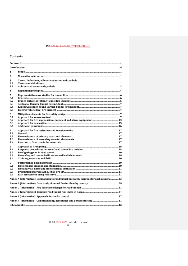
Contents
Foreword . v
Introduction . vi
1 Scope . 1
2 Normative references . 1
3 Terms, definitions, abbreviated terms and symbols . 1
3.1 Terms and definitions . 1
3.2 Abbreviated terms and symbols . 3
4 Regulation principles . 4
5 Representative case studies for tunnel fires . 6
5.1 General. 6
5.2 France-Italy: Mont-Blanc Tunnel fire incident . 6
5.3 Australia: Burnley Tunnel fire incident . 7
5.4 Korea: Gwacheon Sound Barrier Tunnel fire incident . 7
5.5 Electric vehicle (EV) fire incident . 7
6 Mitigation elements for fire safety design . 7
6.1 Approach for smoke control . 7
6.2 Approach for fire suppression equipment and alarm equipment . 13
6.3 Approach for evacuation . 15
6.4 Additional provisions . 16
7 Approach for fire resistance and reaction to fire . 17
7.1 General. 17
7.2 Fire resistance of primary structural elements . 17
7.3 Fire resistance of secondary structural elements. 17
7.4 Reaction to fire criteria for materials . 17
8 Approach to firefighting . 18
8.1 Response procedures in case of road tunnel fire incident . 18
8.2 Firefighting plan in road tunnel . 19
8.3 Fire safety and rescue facilities in small vehicle tunnels . 19
8.4 Training, exercises and drill . 20
9 Performance-based approach . 20
9.1 Fire scenario creation and standards . 20
9.2 Fire analysis: flame and smoke spread simulation . 21
9.3 Evacuation analysis: ASET/RSET or FED . 21
9.4 Risk assessment using F/N curve . 21
Annex A (informative) Comparison to road tunnel fire safety facilities for each country . 23
Annex B (informative) Case study of tunnel fire incident by country . 29
Annex C (informative) Fire resistance design for road tunnels . 31
Annex D (informative) Example road tunnel risk index in Korea . 34
Annex E (informative) Approach for smoke control . 37
Annex F (informative) Commissioning, acceptance and periodic testing . 41
Bibliography . 42
© ISO #### 2026 – All rights reserved
iv
Foreword
ISO (the International Organization for Standardization) is a worldwide federation of national standards
bodies (ISO member bodies). The work of preparing International Standards is normally carried out through
ISO technical committees. Each member body interested in a subject for which a technical committee has been
established has the right to be represented on that committee. International organizations, governmental and
non-governmental, in liaison with ISO, also take part in the work. ISO collaborates closely with the
International Electrotechnical Commission (IEC) on all matters of electrotechnical standardization.
The procedures used to develop this document and those intended for its further maintenance are described
in the ISO/IEC Directives, Part 1. In particular, the different approval criteria needed for the different types of
ISO documentsdocument should be noted. This document was drafted in accordance with the editorial rules
of the ISO/IEC Directives, Part 2 (see www.iso.org/directives).
ISO draws attention to the possibility that the implementation of this document may involve the use of (a)
patent rights.(s). ISO takes no position concerning the evidence, validity or applicability of any claimed patent
rights in respect thereof. As of the date of publication of this document, ISO had not received notice of (a)
patent rights(s) which may be required to implement this document. However, implementers are cautioned
that this mightmay not represent the latest information, which may be obtained from the patent database
available at www.iso.org/patents. ISO shall not be held responsible for identifying any or all such patent
rights.
Any trade name used in this document is information given for the convenience of users and does not
constitute an endorsement.
For an explanation of the voluntary nature of standards, the meaning of ISO specific terms and expressions
related to conformity assessment, as well as information about ISO's adherence to the World Trade
Organization (WTO) principles in the Technical Barriers to Trade (TBT), see www.iso.org/iso/foreword.html.
This document was prepared by Technical Committee ISO/TC92TC 92, Fire Safety, Working Group 15, Road
Tunnel Fire Safetysafety.
Any feedback or questions on this document should be directed to the user’s national standards body. A
complete listing of these bodies can be found at www.iso.org/members.html.
© ISO #### 2026 – All rights reserved
v
ISO #####-#:####(X/DTR 24488:(en)
Introduction
Fire safety is an issue of increasing importance in road tunnel design and operation, given the potential for
high-consequence events involving loss of life, significant property damage, and operational disruption.
National regulations and technical guidelines for tunnel fire safety have been established in various countries
and regions, reflecting differences in regional conditions, design practices, and risk management approaches.
In parallel, international and regional references such as EU Directive 2004/54/EC, NFPA standards, and
PIARC technical reports provide important guidance for the design, operation, and safety management of road
tunnels. However, a consolidated reference addressing fire safety in road tunnels from an international
perspective has not yet been established within the ISO framework. This document is intended to contribute
to that effort by bringing together existing regulatory frameworks, engineering approaches, and research
relevant to tunnel fire safety.
This document is informative in nature. It provides an overview of existing regulatory frameworks and
technical approaches related to fire safety in road tunnels, synthesizing current practices and relevant
research to support knowledge sharing and to serve as a consolidated reference for fire safety considerations
in tunnel design and operation.
The objective of this document is to facilitate understanding of diverse regulatory and technical approaches
and to support improved consistency between national practices and internationally recognized safety
principles.
© ISO #### 2026 – All rights reserved
vi
Road tunnel fire safety — Overview of regulatory frameworks and
research
1 Scope
This document presents information on fire safety design and facilities for mitigating fire risks in road tunnels.
It describes the regulatory frameworks for road tunnel fire safety in various countries and regions, along with
general principles and selected case studies. TheThis document includes updated engineering applications
and internationally applied approaches relevant to fire protection and life safety in road tunnels.
2 Normative references
The following documents are referred to in the text in such a way that some or all of their content constitutes
requirements of this document. For dated references, only the edition cited applies. For undated references,
the latest edition of the referenced document (including any amendments) applies.
ISO 13943, Fire safety — Vocabulary
3 Terms, definitions, abbreviated terms and Definitionssymbols
For the purposes of this document, the terms and definitions given in ISO 13943 and the following apply.
ISO and IEC maintain terminology databases for use in standardization at the following addresses:
ISO and IEC maintain terminology databases for use in standardization at the following addresses:
— ISO Online browsing platform: available at https://www.iso.org/obp
— IEC Electropedia: available at https://www.electropedia.org/
3.1 3.1Terms and definitions
3.1.1
tunnel length
length measured from portal face to portal face along the centreline alignment of the tunnel roadway
3.1.2
3.2
ventilation system
Technicaltechnical system designed to supply fresh air or exhaust polluted air in the tunnel for diluting or
exhausting polluted air
3.1.3 3.3
mechanical ventilation
The system utilizing fans and powered equipment to actively control the airflow for two primary purposes:
diluting pollutants during normal operation and managing smoke and heat in a fire emergency
© ISO #### 2026 – All rights reserved
ISO #####-#:####(X/DTR 24488:(en)
3.1.4 3.4
longitudinal ventilation system
longitudinal ventilation system (3.1.2) that supply air from the tunnel entrance, vertical shafts, or side shafts
to form a longitudinal airflow, and exhaust polluted air from the traffic or fire smoke from tunnel exits, vertical
shafts, or side shafts
3.1.5 3.5
transverse ventilation system
ventilation system (3.1.2) that simultaneously performs fresh air supply and exhaust through supply and
exhaust ducts installed in the tunnel, which introduces fresh air during normal operation and exhausts smoke
generated by a fire during a fire
3.1.6 3.6
safe area
space for evacuation of tunnel users or firefighting activities for firefighters in the event of a fire or disaster in
the tunnel, protected from heat and smoke generated by the fire
3.1.7
3.7
sound barrier tunnel
length of roadway enclosed by a roofed structure and side barriers constructed primarily for traffic noise
mitigation through sound absorption or shielding
3.1.8
3.8
fixed water-based firefighting system
FFFS
technical system that sprays water at high, medium, or low pressure through a head or nozzle, typically
consists of a pump, valve, piping, and heads or nozzles
3.1.9 3.9
smoke control
Directingdirection and managingmanagement of the smoke and heat currents generated during a fire from
the fire area
Note 1 to entry: The term smoke ventilation is often used to refer specifically to exhausting smoke and heat.
3.1.10 3.10
smoke exhaust
process of exhausting fire smoke and heat generated during a fire from the fire area to the outside
3.1.11
3.11
jet fan
axial fan that can induce and maintain a controlled longitudinal airflow for the purpose of pollution dilution
and smoke management, generally under a tunnel ceiling which transmits momentum to the air
© ISO #### 2026 – All rights reserved
3.1.12
3.12
piston effect
effect in which air resistance caused by moving vehicles through the tunnel generates airflow, contributing to
the production of longitudinal ventilation flow
3.1.13
3.13
critical velocity
minimum longitudinal velocity required to prevent the backlayering (0) of the heat (smoke) flow
3.1.14 3.14
backlayering
The movement of smoke and hot gases counter to the direction of the ventilation airflow
3.1.15 3.15
smoke stratification
phenomenon in which the fire smoke forms a smoke layer in the upper part of the tunnel due to buoyancy
caused by gas temperature differences.
Note 1 to entry: It varies depending on fire size, tunnel geometry, intervene of mechanical and natural ventilation, tunnel
slope and distance from the fire source.
3.2 Abbreviated terms and symbols
AADT annual average daily traffic
ASET available safe egress time
BEV battery electric vehicle
CFD computational fluid dynamics
EV electric vehicle
FCEV fuel cell electric vehicle
FED fractional effective dose
FTA fault tree analysis
HGV heavy goods vehicle
HRR heat release rate
ICEV internal combustion engine vehicle
LIB lithium-ion battery
NMC nickel-manganese-cobalt
pHRR peak heat release rate
PMMA polymethyl methacrylate
QRA quantitative risk assessment
RSET intended safe egress time
SOC state of charge
© ISO #### 2026 – All rights reserved
ISO #####-#:####(X/DTR 24488:(en)
SUV sport utility vehicle
THR total heat released
UPS uninterruptible power supply
A tunnel cross-sectional area perpendicular to the flow (m )
CP specific heat of air (kJ/kg/K)
g acceleration due to gravity (m/s )
H height from base of fire to tunnel ceiling at the fire site (m)
K critical Froude number factor, as provided in Table E.1
ρ density of approach (upstream) air (kg/m )
Q convective heat release rate at the fire site (kW)
T temperature of approach air (K)
Tf average temperature of gases at the fire site (K)
V critical velocity (m/s)
c
4 Regulation principles
Road tunnel fire safety regulations vary across countries and regions, reflecting differences in regulatory
approaches, classification criteria, and the responsible management bodies. Common classification criteria
include tunnel length (3.1.1(3.1),), traffic volume, and risk assessment methods.
In the United Kingdom, tunnel grades are classified based on tunnel length and projected traffic volume over
a 15-year period.
In France, fire safety facilities are required for tunnels of 300 m or longer on highways and arterial roads, with
higher standards applied for specific road categories.
In Germany, facility specifications are determined primarily by tunnel length, with 400 m, 600 m, and 900 m
serving as reference thresholds. Road characteristics are additionally considered when determining facility-
specific requirements.
In the United States, national safety standards prescribe the installation of fire safety facilities in tunnels and
provide criteria for determining fire safety grades based on traffic volume (see NFPA 502:2026 [22],,[22]
A.7.2). The Federal Highway Administration (FHWA) has additionally published reports covering tunnel fire
incident analysis and safety evaluation methodologies. Detailed installation specifications are not prescribed;
instead, fire safety evaluation standards serve as the basis for determining the appropriate scale of facilities.
In Sweden, tunnel classification is based on tunnel length and traffic volume, with length thresholds ranging
from 500 m to 3 ,000 m.
In many countries and regions beyond those described above, NFPA 502 is widely referenced in the design,
installation, and operation of road tunnel fire protection facilities.
Annex AAnnex A provides a comparative overview of fire safety facility provisions in selected countries.
© ISO #### 2026 – All rights reserved
Table 1 — Standards and management agency for road tunnel safety facilities in various countries
Country/Re
Standards Management agency
gion
NFPA 502: Standard for Road Tunnels,
National Fire Protection Association, NFPA
United States Bridges, and Other Limited Access
(international consensus standard)
Highways[7] [7]
The Highways Agency
United
CD 352 Design of road tunnels[11] [11]
Kingdom
(guidelines requirements)
Inter-ministerial circular no 2002-63 of 25
Ministry for Infrastructure, Transport, Spatial
August 2002 concerning Safety in the
Planning, Tourism, and the Sea
France
Tunnels of National Route Network[25]. etc.
(government directive guidelines)
[25]
Guidelines for the Design, Structural
Configuration, and Equipment of Civil
Engineering Structures, Part 3: Tunnels (RE-
Richtlinien für die Ausstattung von Straßentunneln ,
ING, Part 3)
(RABT)
Germany
Recommendations for the Equipment and
(government guidelines)
Operation of Road Tunnels with a Design
Speed of 80 km/h or 100 km/h (RABT-
80/100) [8])[8]
ASTRA (Swiss Federal Roads Office)
Switzerland Lüftung der Strassentunnel[3] [3]
(government guidelines)
Swedish Transport Administration
Sweden Krav Tunnelbyggande[10] [10]
(government guidelines)
Overheid.nl
Regeling aanvullende regels veiligheid
Netherlands
wegtunnels[9] [9]
(government guidelines)
Road Tunnel Emergency Facilities Ministry of Land, Infrastructure, Transport and
Japan
Installation Standards[6] [6] Tourism (national standards)
DIRECTIVE 2004/54/EC OF THE
EUROPEAN PARLIAMENT AND OF THE
European THE EUROPEAN PARLIAMENT AND THE COUNCIL
COUNCIL of 29 April 2004 on minimum
Union OF THE EUROPEAN UNION
safety requirements for tunnels in the
Trans-European Road Network[5] [5]
In the Republic of Korea (hereinafter referred to as Korea), fire safety facilities in road tunnels are determined
by a classification system based on two criteria: tunnel length grade and disaster prevention grade (risk index
X).
The risk index is assessed by evaluating a range of factors, including traffic exposure (tunnel length × traffic
volume), tunnel geometry (longitudinal gradient, tunnel height, and curve radius), the proportion of heavy
vehicles, legal regulations on the transport of hazardous materials, traffic congestion levels (e.g.,. merging or
diverging within the tunnel, upstream intersections such as interchanges, junctions, signals, or tollgates), and
traffic flow type (bidirectional or unidirectional).
Table 1 Table 1 provides the standards and management agencies in various countries. The classification
thresholds are provided in Table 2 Table 2,, and a summary of the detailed evaluation criteria, specifically for
the cases in Korea, is given in Annex DAnnex D.
© ISO #### 2026 – All rights reserved
ISO #####-#:####(X/DTR 24488:(en)
Table 2 — Standard by length grade and fire safety grade in Korea
Grade Tunnel length (L) Risk index (X) standard
1 3 ,000 m or more (L ≧ 3 ,000 m) X > 29
1 ,000 m or more, less than 3 ,000 m (1 ,000 ≦ L <
2 19 < X ≦ 29
3 ,000 m)
500 m or more, less than 1 ,000 m (500 ≦ L <
3 14 < X ≦ 19
1 ,000 m)
4 Less than 500 m (L < 500 m) X ≦ 14
5 Representative case studies for tunnel fires
5.1 General
This clause provides case studies of tunnel fire incidents categorized by technical and environmental factors,
such as initial suppression effectiveness, damage scale, and the involvement of electric vehicles (EVs) or
specific infrastructure like sound barrier tunnels (3.1.7(3.7). ).
For a broader compilation of international incidents, reference is maderefer to Annex BAnnex B.
Fires in road tunnels pose greater risk than fires in open environments due to the closed or semi-closed nature
of the space, which accelerates smoke and heat accumulation and limits evacuation and rescue options.
Depending on the design of safety facilities and emergency response, tunnel fires can escalate into major
incidents or, conversely, have their impacts mitigated.
Fire incidents in road tunnels have involved a range of vehicle types, including passenger cars, motorcycles,
vans, buses, and various heavy goods vehicles (HGVs) carrying diverse cargoes, in some cases including
dangerous goods. Most incidents involving multiple fatalities have involved one or more HGVs. The substantial
fire load associated with these vehicles increases fire intensity, significantly hindering both direct firefighting
and rescue operations.
Timely notification of tunnel users in emergency situations is a key factor in incident outcomes, particularly
in long tunnels. Tunnel designers and operators are also expected to account for human behaviour in tunnel
emergency situations. Furthermore, integrating fire safety from the initial design stage rather than
considering it as a subsequent addition ensures that lessons from past incidents are effectively incorporated.
5This clause presents selected case studies of tunnel fire incidents from various countries, including incidents
involving electric vehicles and sound barrier tunnels. The objective is to illustrate differences in fire
development and response strategies to maintain aan intended level of basic fire safety.
5.2 France-Italy: Mont-Blanc Tunnel fire incident
On 24 March 1999, a fire occurred in the Mont-Blanc Tunnel connecting France and Italy, approximately
6.,3 km from the French portal. The fire originated from an engine failure in a heavy goods vehicle and
subsequently spread to the cargo of margarine and flour, eventually involving additional vehicles. The incident
lasted 53 hours h, resulting in 33 vehicles damaged and 39 fatalities. The average heat release rate was
estimated at 30 MW to 50 MW, with a reported peak of 100 MW. A malfunction in the smoke control (0(3.9))
system was identified as a contributing factor to the scale of casualties. At the time, tunnel operations were
managed separately by France and Italy: the French side operated a combined fresh air supply and ventilation
system, while the Italian side supplied fresh air only, resulting in a failure of coordinated smoke control.
© ISO #### 2026 – All rights reserved
5.3 Australia: Burnley Tunnel fire incident
On 23 March 2007, a fire incident occurred in the Burnley Tunnel in Melbourne, Australia, following a multi-
vehicle collision involving four HGVs and seven light vehicles. The collision resulted in three fatalities and a
fire with subsequent explosions. Emergency ventilation and the FFFS (3.1.8(3.8)) were activated
approximately 2 min after ignition. The FFFS successfully contained the fire, with no significant fire growth
recorded after activation of the deluge system despite the initial severity of the incident.
The Burnley Tunnel is one of a non-identical pair of three-lane tubes serving one of Melbourne's principal toll
road networks, with traffic volumes typically exceeding 100 000 vehicles per day per tube.
5.4 Korea: Gwacheon Sound Barrier Tunnel fire incident
On 29 December 2022, a fire incident occurred in the Gwacheon Sound Barrier Tunnel on the Second Gyeongin
Expressway, when a waste collection vehicle caught fire near the Bukuiwang interchange. The fire affected a
600 m section of the 845 m tunnel, resulting in five fatalities, 46 injuries, and 45 vehicles destroyed. Sound
barrier tunnels share structural characteristics with road tunnels and present similar fire risks, including
rapid temperature rise and smoke spread. The rate of fire spread is influenced by the fire performance of the
sound-absorbing materials installed. In this incident, the tunnel was predominantly lined with PMMA
(polymethyl methacrylate), a material with limited fire resistance, which contributed to the rapid spread of
the fire. The damage was further compounded by the failure of blocking facilities due to a power outage.
5.5 Electric vehicle (EV) fire incident
5.5.1 China: Road tunnel EV fire at Qingshanhu Tunnel in Nanchang
On 8 March 2016, a fire incident occurred in the Qingshanhu Tunnel in Nanchang, China, involving an electric
vehicle. Occupants initially attempted to extinguish the fire without success. Firefighters arrived and
extinguished the fire within approximately 10 minutes min. No casualties resulted, though the tunnel was
filled with smoke and one vehicle was completely destroyed.
5.5.2 United States: Road tunnel EV fire at Big Dig Tunnel in Boston
On 24 May 2024, a fire incident occurred in the tunnel connecting northbound Highway 93 and the eastbound
Massachusetts Turnpike, adjacent to the Ted Williams Tunnel, following a collision involving three vehicles,
one of which was a hybrid electric vehicle. The fire in the non-electrified vehicle was extinguished promptly,
while the hybrid vehicle's battery fire involved significantly longer suppression period. Two vehicles were
completely destroyed. Smoke spread through the exhaust system to parts of the surrounding urban area. Six
occupants were evacuated, of whom three sustained minor injuries.
6 Mitigation elements for fire safety design
6.1 Approach for smoke control
6.1.1 General
Smoke control facilities are installed to manage the movement of smoke in the event of a tunnel fire, to secure
conditions suitable for evacuation and firefighting, and to remove smoke from the tunnel following
extinguishment. The purpose of smoke control facilities is divided into two functions based on the ventilation
method applied: smoke control and smoke exhaust (0(3.10).). Smoke control is applied in longitudinal
ventilation systems (0(3.4),), where airflow is directed away from evacuees to prevent smoke from spreading
in the direction of evacuation. Smoke exhaust is applied in transverse or semi-transverse ventilation systems
(0(3.5),), where smoke is extracted from the fire area through ducts. In tunnels where mechanical ventilation
(0(3.3)) is installed, the ventilation system also serves smoke control functions; accordingly, smoke control
capacity is considered when planning ventilation facilities. See Annex EAnnex E for further details.
© ISO #### 2026 – All rights reserved
ISO #####-#:####(X/DTR 24488:(en)
Smoke control systems function to limit the spread of smoke, maintain tenable conditions for evacuation, and
support firefighting operations. Such systems can include smoke barriers, ventilation enhancement features,
or pressurization elements, installed within main tunnel bores and emergency egress routes. Design
approaches can include longitudinal ventilation, transverse ventilation, and large-port exhaust ventilation
systems.
See Annex EAnnex E for further information on smoke control principles and validation of smoke control
systems.
6.1.2 Ventilation plan in case of fire
6.1.2.1 Fire stages
Smoke control operations during a vehicle fire are typically categorized into two stages based on the fire
development and response objectives:
Stage 1 (Evacuationevacuation phase): Atat the onset of a fire, smoke control systems are operated to maintain
a tenable environment for evacuation. Ventilation is managed to direct smoke flow away from evacuation
routes. In longitudinal ventilation systems (0(3.4),), the control logic for fans is configured to maintain the
critical velocity (3.1.13(3.13)) automatically to prevent backlayering (0(3.14).).
Stage 2 (Firefightingfirefighting support phase): Subsequentsubsequent to the evacuation phase, smoke
control operations are adapted to support firefighting and rescue activities. During this stage, the operation
or cessation of ventilation facilities is performed in close coordination with the on-site fire brigade.
6.1.2.2 Fire size for conventional vehicle
The capacity of smoke control facilities varies depending on the design fire size, critical velocity, and amount
of smoke generated.
Table 3 Table 3 provides the design fire sizes by determined vehicle types.
Table 3 — Design fires by vehicle types
Fire size
Types of vehicles NoteComment
[peak HRR
(MW)]
Considering modern vehicles. Refer, refer to PIARC[20]
passengerPassenger car 5-10
[20]
Based on limited number of studies and subject to
electricElectric vehicle 5-10
further review
busBus 30 Typical value from full scale bus fire tests
smallSmall lorry, up to 25 tonnes 30-50 Refer to PIARC [20]2007 [20]
Refer to Runehamar tests 2003 [13],,[13] PIARC [20],
,[20]NFPA 502[7] [7]
largeLarge lorry (heavy goods
100-200
vehicle), up to (25-50) tonnes
The weight classification of lorries depends on the
quality and nature of the load.
Refer to PIARC [20],,[20] and tank fire incidents (e.g.,.
tankerTanker 200-400 Skatestraum tunnel 2015). 400 MW refers to a tunnel
with a large slope, e.g.,. 10 %.
© ISO #### 2026 – All rights reserved
6.1.2.3 Fire size for electric vehicle
Electric vehicle (EV) fires exhibit different characteristics compared to internal combustion engine vehicles
(ICEVs) due to battery-specific phenomena such as thermal runaway. Data from full-scale fire tests indicate
],[
that the peak heat release rate (pHRR) is influenced by vehicle type and battery configuration[15] [21]. [15,
21].
Comparative analysis of test data shows that a compact EV (100 % SOC) reaches a pHRR of approximately
5 MW to 6 MW, while an SUV-class EV (100 % SOC) reaches 8 MW to 10 MW. The pHRR of the SUV-class EV is
higher than that of an equivalent internal combustion engine SUV. However, fire development patterns remain
similar between the two vehicle types until the onset of direct battery combustion, typically observed around
],[
the 800-seconds mark in experimental conditions[15] [21]. [15, 21].
It is noted that the HRR values in these studies are estimated based on convective heat flows, which involves
a degree of uncertainty compared to the oxygen consumption method[21]. [21] .
Table 4 Table 4 summarizes the test configurations for these experiments. The resulting HRR profiles by
vehicle type are presented in Figure 1 Figure 2.
Table 4 — Overview of tested vehicles and estimated HRR
Battery
Test Vehicle Capacity Ignition source
type/fuel
Thermal runaway triggered by injection of
V1 BEV, compact vehicle NMC 80 kWh
liquid NaCLaq
V2 ICEV Diesel Unknown Fire start from burning interior
Fire start from interior, external triggering of
V3 BEV, SUV NMC 80 kWh the thermal runaway after 10 min of vehicle
into battery case
a) Comparison of V1 (BEV, compact vehicle) and V3 (BEV, SUV)
© ISO #### 2026 – All rights reserved
ISO #####-#:####(X/DTR 24488:(en)
b) Comparison of V2 (ICEV) and V3 (BEV, SUV)
Key
X time [s]
Y HRR [MW]
1 V1 (BEV)
2 V3 (BEV, SUV)
3 V2 (ICEV, SUV)
SOURCE References [15],[21]
.
Figure 2 1 — Comparison of the HRRs roughly estimated based on convective heat flows
(a) Comparison of V1 (BEV, compact vehicle) and V3 (BEV, SUV)
(b) Comparison of V2 (ICEV) and V3 (BEV, SUV)
NOTE Source: Reference [15, 21]
Full-scale fire test data indicate the respective heat release contributions from the battery pack and the vehicle
body of a BEV (64 -kWh). The pHRR and total heat released (THR) values are recorded as 1.,54 MW and 1.,30
GJ for the LIB pack, and 7.,81 MW and 7.,53 GJ for the vehicle body.
In an integrated vehicle fire test, the recorded pHRR and THR are 7.,25 MW and 9.,03 GJ, respectively. This
THR is comparable to the combined sum of the individual components (8.83 GJ). The data show that the
© ISO #### 2026 – All rights reserved
combustion of the vehicle body, specifically within the passenger cabin, contributes a larger portion of the
pHRR and THR compared to the battery pack, even when thermal runaway occurs.
Table 5 Table 5. summarizes the thermal hazard measures for each component and vehicle type. Time-
dependent profiles of HRR and THR are presented in Figure 2 Figure 3.
Table 5 — Measures of thermal hazards of vehicle fires
LIB pack of Body of
Measures BEV_2 BEV_3 ICEV FCEV
BEV_1 BEV_1
Peak heat
release rate, 1.,54 7.,81 6.,61 7.,25 7.,66 5.,99
pHRR ([MW)]
Total heat
released, THR 1.,30 7.,53 8.,45 9.,03 8.,08 10.,82
([GJ)]
© ISO #### 2026 – All rights reserved
ISO #####-#:####(X/DTR 24488:(en)
Figure 3 — Time-dependent profiles of
Key
X time [min]
Y1 heat release rate [MW]
Y2 total heat released [GJ]
1 HRR and (LIB pack)
2 HRR (BEV#2)
3 HRR (ICEV)
4 THR (LIB pack)
5 THR (BEV#2)
6 THR (ICEV)
7 HRR (BEV body)
8 HRR (BEV#3)
9 HRR (FCEV)
10 THR (BEV body)
11 THR (BEV#3)
12 THR (FCEV)
NOTE 1 The profiles show the temporal variation of HRR and THR for the tested vehicle configurations.
NOTE 2 SOURCE : Reference [15] [15] .
The symbols and abbreviated terms used in this clause are defined as follows:
Nomenclature
EV : Electric vehicle
© ISO #### 2026 – All rights reserved
BEV : battery electric vehicle
ICEV : internal combustion engine vehicle
SUV : sport utility vehicle
FCEV : fuel cell electric vehicle
SOC : state of charge
HRR : heat release rate
pHRR : peak heat release rate
THR : total heat released
NMC : Nickel-Manganese-Cobalt
LIB : Lithium-ion battery
Figure 2 — Time-dependent profiles of HRR and THR
6.1.2.4 Critical velocity inside tunnels
Extensive research exists regarding the critical velocity for smoke control in tunnels with longitudinal
ventilation. Various empirical and semi-empirical correlations are utilized to calculate this
],[ ],[ ],[ ],[ ],[34
parameter[16] [17] [19] [22] [23] [16, 17, 19, 22, 23, 34]. .
The critical velocity is primarily influenced by the fire size (expressed as heat release rate), tunnel geometry,
and potential blockage effects. Further technical details on smoke control are provided in Annex EAnnex E.
While these correlations provide estimates for design, technical documentation from PIARC[20] [20] and
NFPA 502[27] [27] indicates that the applicability of simplified models is limited under certain conditions,
such as complex tunnel geometries, large fire sizes, or non-uniform ventilation profiles. In practice,
computational fluid dynamics (CFD) analysis is employed to evaluate the calculated critical velocity across
diverse tunnel configurations and fire scenarios.
6.2 Approach for fire suppression equipment and alarm equipment
6.2.1 General
The following subclauses describe engineering approaches for active fire protection systems in road tunnels,
drawing on the research findings and incident cases discussed above.
Active protection encompasses equipment designed to detect and respond to emergency situations, such as
fires and traffic incidents. Such equipment serves to relay incident information promptly to tunnel operators,
emergency services, and tunnel users, and to facilitate fire control and extinguishment. The applicability and
configuration of these systems vary depending on tunnel geometry, traffic characteristics, and the results of
risk assessment.
See Annex FAnnex F for further information on commissioning and periodic testing.
© ISO #### 2026 – All rights reserved
ISO #####-#:####(X/DTR 24488:(en)
6.2.2 Fire suppression equipment
Fire suppression equipment deployed within road tunnels serves to manage and extinguish fires, particularly
those involving vehicles. This equipment includes fire extinguishers, fire hydrants, fixed water-based
firefighting systems (including water mist suppression systems), and remote-controlled fire sprinkler systems
intended for small vehicle tunnels and sound barrier tunnels. These systems are categorized into manual and
automatic modes of operation.
Table 7 Table 7 summarizes examples of active fire protection systems and their functional roles within the
tunnel environment.
Table 7 — Functional roles and characteristics of fire suppression systems
Sub- Primary function and
Category Key features and notes
systemSubsystem
objective
Enable the initial control or Strategically placed at regular
potablePotable fire extinguishment of small-scale intervals along the tunnel and
extinguishers incipient fires to support self- within emergency cross-
rescue. passages.
Fire Includes remote-controlled
Extinguish fires by discharging
suppression fireFire hydrant water spray systems for small
firefighting water through hoses
vehicle tunnels and sound barrier
equipment systems
and spray nozzles.
tunnels.
Actively mitigate fire consequences Categorized by performance: fire
fixedFixed water-based
by restricting growth rate or suppression, fire control, volume
firefighting systems
cooling structural elements. cooling, and surface cooling.
6.2.3 Fire alarm systems
Fire alarm systems consist of an integrated network of devices, including automatic detection sensors and
manual alarm stations, engineered to provide the earliest possible notification of a fire or related emergency
within the tunnel. These systems are essential for initiating defined emergency response plans, automatically
communicating the precise location of an incident to the tunnel control centre, and triggering the coordinated
activation of other critical life safety and firefighting systems, such as emergency ventilation and traffic
management measures.
Table 8 Table 8 summarizes examples of active fire alarm systems and their functional roles within the tunnel
environment.
Table 8 — Functional roles and characteristics of fire alarm systems
Sub-
Primary function and
Category Key features and notes
systemSubsystem objective
Manually operated by incident Utilizes transmitters (push
manualManual alert
participants or witnesses to report buttons) and emergency bells to
systems
incidents and trigger alerts. inform road users.
Continuously monitor the
Employs linear heat detectors,
Fire alarm automaticAutomatic environment to automatically
video image detection systems,
systems fire detection systems identify the presence, location, and
or point-type detectors.
nature of a fire.
Provide unambiguous, real-time High-intelligibility audio system
emergencyEmergency
instructions and safety guidance to using loudspeakers and/or radio
broadcasting systems
tunnel occupants. rebroadcasting equipment.
© ISO #### 2026 – All rights reserved
Sub-
Primary function and
Category Key features and notes
systemSubsystem
objective
Dedicated phones for incident
Used by participants or witnesses
emergencyEmergency participants to contact road
to contact road administrators
phones administrators and report
and others.
emergencies.
Integrated with Video Image
automaticAutomatic AnalyzeAnalyse visual information
Detectionvideo image detection
incident detection or detection data to automatically
(VID) technology for active fire
equipment alert the management system.
indicator analysis.
Enable broadcast reception within Captures, amplifies, and
rebroadcastRebroadcas
the tunnel and provide emergency transmits signals through leaky
t equipment
broadcasting in urgent situations. coaxial cables or antennas.
Convey information about
Encompasses tunnel entrance
informationInformation emergencies, maintenance, or
signs, lane control signals, and
signage construction to drivers inside and
entry barriers.
outside the tunnel.
Notify and block vehicles
Positioned at the tunnel’s front
Traffic and tunnelTunnel entry attempting to enter during
entrance for immediate
access control blocking equipment emergencies to prevent secondary
intervention.
incidents.
Ensure immediate and systematic
Critical for minimizing the
tunnelTunnel closure management of traffic flow,
population at risk and facilitating
and traffic control clearing the tube for evacuation
emergency services.
and access.
Efficiently collect, store, and
Constructed exclusively of non-
tunnelTunnel drainage discharge all effluent, including
combustible materials such as
system firefighting water and hazardous
steel, ductile iron, or concrete.
Hazard and
spills.
fluid
Provi
...