

SIST EN IEC 60255-26:2025/FprA1:2026
(Amendment)Measuring relays and protection equipment - Part 26: Electromagnetic compatibility requirements - Amendment 1
General Information
- Abstract
- Status
- Not Published
- Public Enquiry End Date
- 19-Nov-2026
- Technical Committee
- ISS EIT.ERE - All-or-nothing electrical relays
- Current Stage
- 4020 - Public enquire (PE) (Adopted Project)
- Start Date
- 09-Sep-2026
- Due Date
- 27-Jan-2027

Overview
SIST EN IEC 60255-26:2025/FprA1:2026 is an Amendment to the established standard for electromagnetic compatibility (EMC) requirements for measuring relays and protection equipment. Developed by CLC and the IEC Technical Committee 95, this amendment refines and clarifies EMC test procedures, port definitions, and compliance criteria for relays and associated protection devices. It aims to ensure that protection equipment continues to function correctly in environments affected by electromagnetic disturbances, supporting reliability in electricity generation, transmission, and distribution.
Key Topics
- Updated Definitions: New terminologies, such as DC power output port and analogue input signal port, are introduced to better specify the interfaces subjected to EMC tests.
- Clarified Emission and Immunity Tests: The amendment revises tables for radiated and conducted emission tests, as well as immunity tests for various ports. Corrections address emission limits, source impedances, and environmental conditions for testing.
- Port-Specific Requirements: Immunity and emission requirements are updated for new and existing port categories, including DC power output ports and analogue signal ports, ensuring each interface is tested appropriately for real-world use.
- Adoption of EMC Basic Standards: The amendment aligns testing procedures with referenced standards (e.g., CISPR 11, CISPR 32, IEC 61000-4 series), increasing harmonization and reliability of test methods.
- Realistic Use Scenarios: Exemptions and clarifications are included for ports or cables under specific length or shielding conditions, preventing unnecessary testing while maintaining robust EMC performance.
Applications
SIST EN IEC 60255-26:2025/FprA1:2026 is critical in the following areas:
- Power System Protection: Ensures that relays and related equipment remain immune to electromagnetic interference, safeguarding critical infrastructure.
- Component Testing and Certification: Manufacturers of measuring relays and protection equipment use this standard to validate products for EMC compliance, supporting certification and market access.
- System Integration: Engineers in grid automation or industrial automation integrate compliant relays to ensure reliable operation throughout the system lifecycle.
- Quality Assurance: Utilities and service providers rely on EMC-compliant devices to maintain service quality and operational reliability in harsh electromagnetic environments.
Related Standards
Users of SIST EN IEC 60255-26:2025/FprA1:2026 often rely on the following international standards:
- IEC 61000-4 Series: Core EMC testing methodologies covering immunity and emission measurements.
- CISPR 11 & CISPR 32: Standards for radiated and conducted emissions for industrial, scientific, and multimedia devices.
- IEC 60255 Series: General requirements for measuring relays and protection equipment, including functional tests and performance criteria.
- IEC 60050-447: International Electrotechnical Vocabulary for definitions related to protective relays.
Practical Value
Adhering to this amendment ensures:
- Consistent Product Performance: Through clearly defined EMC testing boundaries and acceptance criteria.
- Regulatory Compliance: Facilitates conformity with European and international EMC directives, enhancing marketability and legal certainty.
- Reduced Risk of Malfunction: Systematic EMC testing ensures that protection equipment operates correctly under typical and extreme electromagnetic conditions.
- Optimized Test Procedures: Eliminates ambiguities and unnecessary tests, streamlining product development and approval cycles.
For manufacturers, engineering professionals, and operators in the electrical utilities and industrial automation sectors, adopting SIST EN IEC 60255-26:2025/FprA1:2026 is essential to deliver safe, robust, and high-performance protection solutions in the context of growing electromagnetic challenges.
Relations
- Effective Date
- 16-Sep-2025
Get Certified
Connect with accredited certification bodies for this standard

IMQ S.p.A. (Certification)
Italian electrical product certification.

SLG Prüf- und Zertifizierungs GmbH
German testing and certification body.

UL Solutions
Global safety science company with testing, inspection and certification.
Sponsored listings
Frequently Asked Questions
SIST EN IEC 60255-26:2025/FprA1:2026 is a draft published by the Slovenian Institute for Standardization (SIST). Its full title is "Measuring relays and protection equipment - Part 26: Electromagnetic compatibility requirements - Amendment 1". This standard covers: Measuring relays and protection equipment - Part 26: Electromagnetic compatibility requirements - Amendment 1
Measuring relays and protection equipment - Part 26: Electromagnetic compatibility requirements - Amendment 1
SIST EN IEC 60255-26:2025/FprA1:2026 is classified under the following ICS (International Classification for Standards) categories: 29.120.70 - Relays; 33.100.01 - Electromagnetic compatibility in general. The ICS classification helps identify the subject area and facilitates finding related standards.
SIST EN IEC 60255-26:2025/FprA1:2026 has the following relationships with other standards: It is inter standard links to SIST EN IEC 60255-26:2025. Understanding these relationships helps ensure you are using the most current and applicable version of the standard.
SIST EN IEC 60255-26:2025/FprA1:2026 is available in PDF format for immediate download after purchase. The document can be added to your cart and obtained through the secure checkout process. Digital delivery ensures instant access to the complete standard document.
Standards Content (Sample)
SLOVENSKI STANDARD
01-november-2026
Merilni releji in zaščitna oprema - 26. del: Zahteve za elektromagnetno združljivost
- Dopolnilo A1
Measuring relays and protection equipment - Part 26: Electromagnetic compatibility
requirements - Amendment 1
Messrelais und Schutzeinrichtungen - Teil 26: Anforderungen an die elektromagnetische
Verträglichkeit
Relais de mesure et dispositifs de protection - Partie 26: Exigences de compatibilité
électromagnétique
Ta slovenski standard je istoveten z: EN IEC 60255-26:2025/prA1:2026
ICS:
29.120.70 Releji Relays
33.100.01 Elektromagnetna združljivost Electromagnetic compatibility
na splošno in general
2003-01.Slovenski inštitut za standardizacijo. Razmnoževanje celote ali delov tega standarda ni dovoljeno.
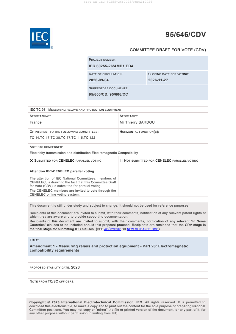
95/646/CDV
COMMITTEE DRAFT FOR VOTE (CDV)
PROJECT NUMBER:
IEC 60255-26/AMD1 ED4
DATE OF CIRCULATION: CLOSING DATE FOR VOTING:
2026-09-04 2026-11-27
SUPERSEDES DOCUMENTS:
95/600/CD, 95/606/CC
IEC TC 95 : MEASURING RELAYS AND PROTECTION EQUIPMENT
SECRETARIAT: SECRETARY:
France Mr Thierry BARDOU
OF INTEREST TO THE FOLLOWING COMMITTEES: HORIZONTAL FUNCTION(S):
TC 14,TC 17,TC 38,TC 77,TC 115,TC 122
ASPECTS CONCERNED:
Electricity transmission and distribution,Electromagnetic Compatibility
SUBMITTED FOR CENELEC PARALLEL VOTING NOT SUBMITTED FOR CENELEC PARALLEL VOTING
Attention IEC-CENELEC parallel voting
The attention of IEC National Committees, members of
CENELEC, is drawn to the fact that this Committee Draft
for Vote (CDV) is submitted for parallel voting.
The CENELEC members are invited to vote through the
CENELEC online voting system.
This document is still under study and subject to change. It should not be used for reference purposes.
Recipients of this document are invited to submit, with their comments, notification of any relevant patent rights of
which they are aware and to provide supporting documentation.
Recipients of this document are invited to submit, with their comments, notification of any relevant “In Some
Countries” clauses to be included should this proposal proceed. Recipients are reminded that the CDV stage is
the final stage for submitting ISC clauses. (SEE AC/22/2007 OR NEW GUIDANCE DOC).
TITLE:
Amendment 1 - Measuring relays and protection equipment - Part 26: Electromagnetic
compatibility requirements
PROPOSED STABILITY DATE: 2028
NOTE FROM TC/SC OFFICERS:
•
download this electronic file, to make a copy and to print out the content for the sole purpose of preparing National
Committee positions. You may not copy or "mirror" the file or printed version of the document, o r any part of it, for
any other purpose without permission in writing from IEC.
IEC CDV 60255-26/AMD1 © IEC 2026
1 INTERNATIONAL ELECTROTECHNICAL COMMISSION
2 ____________
4 MEASURING RELAYS AND PROTECTION EQUIPMENT –
6 Part 26: Electromagnetic compatibility requirements
8 AMENDMENT 1
10 FOREWORD
11 1) The International Electrotechnical Commission (IEC) is a worldwide organization for standardization comprising
12 all national electrotechnical committees (IEC National Committees). The object of IEC is to promote international
13 co-operation on all questions concerning standardization in the electrical and electronic fields. To this end and
14 in addition to other activities, IEC publishes International Standards, Technical Specifications, Technical Reports,
15 Publicly Available Specifications (PAS) and Guides (hereafter referred to as “IEC Publication(s)”). Their
16 preparation is entrusted to technical committees; any IEC National Committee interested in the subject dealt with
17 may participate in this preparatory work. International, governmental and non-governmental organizations liaising
18 with the IEC also participate in this preparation. IEC collaborates closely with the International Organization for
19 Standardization (ISO) in accordance with conditions determined by agreement between the two organizations.
20 2) The formal decisions or agreements of IEC on technical matters express, as nearly as possible, an international
21 consensus of opinion on the relevant subjects since each technical committee has representation from all
22 interested IEC National Committees.
23 3) IEC Publications have the form of recommendations for international use and are accepted by IEC National
24 Committees in that sense. While all reasonable efforts are made to ensure that the technical content of IEC
25 Publications is accurate, IEC cannot be held responsible for the way in which they are used or for any
26 misinterpretation by any end user.
27 4) In order to promote international uniformity, IEC National Committees undertake to apply IEC Publications
28 transparently to the maximum extent possible in their national and regional publications. Any divergence between
29 any IEC Publication and the corresponding national or regional publication shall be clearly indicated in the latter.
30 5) IEC itself does not provide any attestation of conformity. Independent certification bodies provide conformity
31 assessment services and, in some areas, access to IEC marks of conformity. IEC is not responsible for any
32 services carried out by independent certification bodies.
33 6) All users should ensure that they have the latest edition of this publication.
34 7) No liability shall attach to IEC or its directors, employees, servants or agents including individual experts and
35 members of its technical committees and IEC National Committees for any personal injury, property damage or
36 other damage of any nature whatsoever, whether direct or indirect, or for costs (including legal fees) and
37 expenses arising out of the publication, use of, or reliance upon, this IEC Publication or any other IEC
38 Publications.
39 8) Attention is drawn to the Normative references cited in this publication. Use of the referenced publications is
40 indispensable for the correct application of this publication.
41 9) IEC draws attention to the possibility that the implementation of this document may involve the use of (a)
42 patent(s). IEC takes no position concerning the evidence, validity or applicability of any claimed patent rights in
43 respect thereof. As of the date of publication of this document, IEC had not received notice of (a) patent(s), which
44 may be required to implement this document. However, implementers are cautioned that this may not represent
45 the latest information, which may be obtained from the patent database available at https://patents.iec.ch. IEC
46 shall not be held responsible for identifying any or all such patent rights.
47 Amendment 1 to IEC 60255-26:2023 has been prepared by subcommittee MT2:
48 electromagnetic Compatibility (EMC) Requirements for Measuring Relays and Protection
49 Equipment, of IEC technical committee 95: Measuring relays and protection equipment.
50 The text of this Amendment is based on the following documents:
Draft Report on voting
XX/XX/XXXX XX/XX/XXX
52 Full information on the voting for its approval can be found in the report on voting indicated in
53 the above table.
IEC CDV 60255-26/AMD1 © IEC 2026
54 The language used for the development of this Amendment is English.
55 This document was drafted in accordance with ISO/IEC Directives, Part 2, and developed in
56 accordance with ISO/IEC Directives, Part 1 and ISO/IEC Directives, IEC Supplement, available
57 at www.iec.ch/members_experts/refdocs. The main document types developed by IEC are
58 described in greater detail at www.iec.ch/publications/.
59 The committee has decided that the contents of this document will remain unchanged until the
60 stability date indicated on the IEC website under webstore.iec.ch in the data related to the
61 specific document. At this date, the document will be
62 • reconfirmed,
63 • withdrawn, or
64 • revised.
IEC CDV 60255-26/AMD1 © IEC 2026
69 3 Terms and definitions
70 3.1.23
71 Replace the Figure by the following
75 Add the following new definitions:
76 3.1.28
77 DC power output port
78 output port of a DC power supply interface to energize auxiliary equipment. The DC power
79 output port is not used for communicating with auxiliary equipment.
80 3.1.29
81 Analogue input signal port
82 input signal whose value is directly proportional to measured physical quantity with a maximum
83 voltage of less than 50 V and a maximum current of less than 100 mA. (e.g. RTD, 20 mA
84 interface)
85 [SOURCE: IEC 60050-447:2020-05, 447-03-19, modified – “with a maximum voltage of less than 50 V and a maximum
86 current of less than 100 mA. (e.g. RTD, 20 mA interface)” has been added to the definition]
87 3.1.30
88 Pick-up signal
89 output signal that asserts when a measuring relay or protection equipment starts (picks up)
90 [SOURCE: IEC 60050-447:2020-05, 447-04-13]
91 Note 1: Start signal (pick-up signal), among all output signals, can be dedicated or not.
IEC CDV 60255-26/AMD1 © IEC 2026
94 5.2 Conducted emission
95 Add the following text before Table 3
96 No conducted emission requirements apply to DC power output ports in conjunction with CISPR
97 H standards
99 5.1 Radiated emission
100 Replace table 1 with the following new table
101 - Radiated emission limit (above 1 GHz) has been corrected in item 1.2 based on CISPR 32:2015/AMD1:2019
103 Table 1 – Radiated emission tests – Enclosure port
Reference Test
standard procedure
Environmental
Item Frequency range Limits (reference to
phenomena
this
document)
40 dB (µV/m) quasipeak
at 10 m
30 MHz to 230 MHz
50 dB (µV/m) quasipeak
Radiated
at 3 m
emission
1.1 CISPR 11 See 7.2.2
a
47 dB (µV/m) quasipeak
(below 1 GHz)
at 10 m
230 MHz to 1 000 MHz
57 dB (µV/m) quasipeak
at 3 m
60 dB (µV/m) average
Radiated
at 3 m
1.2 emission 1 GHz to 6 GHz CISPR 32 See 7.2.2
80 dB (µV/m) peak
(above 1 GHz)
at 3 m
a
Measuring relays and protection equipment are apparatus which satisfy the class A limits. Limits can be
measured at a nominal distance of 3 m or 10 m or 30 m. A measuring distance less than 10 m is allowed only
for equipment which complies with the definition for "small equipment" given in 3.1.26. In the case of
measurements at a separation distance of 30 m, an inverse proportionality factor of 20 dB per decade shall be
used to normalize the measured data to the specified distance for determining compliance.
At the transition frequency, the more stringent limit shall apply.
107 6.3 Immunity of signal/control port and wired network port
108 Replace table 7 with the following new table
109 - source impedance is removed from the item 7.4 to prevent inconsistencies with the application of the EMC
110 basic standard.
IEC CDV 60255-26/AMD1 © IEC 2026
111 Table 7 – Immunity tests – signal/control port and wired network port
Item Environmental Test Units Basic EMC Test Acceptance
phenomena specification publication procedure criteria
(see 8.2)
7.1 Conducted disturbance
induced by radio-
frequency fields
Frequency sweep
Test frequency range 0,15 to 80 MHz
Test level (prior to 10 V (RMS)
modulation)
Source impedance 150 Ω
Amplitude 80 % AM (1 kHz)
modulated
IEC
Frequency step size ≤ 1 % (of preceding
See 7.3.7 A
61000-4-6
frequency value)
Spot frequencies
Test spot frequencies 27 ± 0,135 MHz
Test level (prior to 10 V (RMS)
modulation)
Source impedance 150 Ω
Amplitude 80 % AM (1 kHz)
modulated
7.2 Electrical fast
transient/burst
Rise time t / 5 / 50 ns
r
Pulse duration t
d
IEC
Test level
See 7.3.4 B
6100044
Zone A 4 kV (peak voltage)
Zone B 2 kV (peak voltage)
Repetition frequency 5 kHz
Source impedance 50 Ω
7.3 Damped oscillatory
waves
Voltage oscillation 1 MHz
frequency
Test level
Common mode 1 kV (peak voltage)
IEC
See 7.3.5 B
61000-4-18
Zone A
Voltage oscillation 3/10/30 MHz
frequency
Test level
Common mode 2 kV (peak voltage)
IEC CDV 60255-26/AMD1 © IEC 2026
Environmental Test Basic EMC Test Acceptance
Item Units
phenomena specification publication procedure criteria
(see 8.2)
7.4 Surge
Front time / 1,2/50 (8/20) µs voltage (current)
Time to half value
Test level
Line-to-Line
IEC
See 7.3.6 B
Zone A 0,5 1 2 kV 61000-4-5
Zone B 0,5 1 kV
Line-to-earth
Zone A 0,5 1 2 4 kV
Zone B 0,5 1 2 kV
IEC CDV 60255-26/AMD1 © IEC 2026
115 Replace the title of clause 6.4 by the following one
117 6.4 Immunity of input, output and DC power output port
118 Replace table 8 with the following new table
119 - Title of the table is updated.
120 - Coupling resistor and coupling capacitor are removed from Item 8.4 for line-to-line and line-to-earth tests
121 to prevent inconsistencies with the application of the EMC basic standard.
122 - Note b is updated
123 Table 8 – Immunity tests – Input, output and DC power output port
Item Environmental Test Units Basic EMC Test Acceptance
phenomena specification publication procedure criteria
(see 8.2)
8.1 Conducted disturbance
induced by radio-
frequency fields
Frequency sweep
Test frequency range 0,15 to 80 MHz
Test level (prior to 10 V (RMS)
modulation)
Source impedance 150 Ω
Amplitude 80 % AM (1 kHz)
modulated
IEC
Frequency step size ≤ 1 % (of preceding
See 7.3.7 A
61000-4-6
frequency value)
Spot frequencies
Test spot frequencies 27 ± 0,135 MHz
Test level (prior to 10 V (RMS)
modulation)
Source impedance 150 Ω
Amplitude 80 % AM (1 kHz)
modulated
8.2 Electrical fast
transient/burst
Rise time t / 5 / 50 ns
r
Pulse duration t
d
IEC
Test level
See 7.3.4 B
61000-4-4
Zone A 4 kV (peak voltage)
Zone B 2 kV (peak voltage)
Repetition frequency 5 kHz
Source impedance 50 Ω
IEC CDV 60255-26/AMD1 © IEC 2026
Environmental Test Basic EMC Test Acceptance
Item Units
phenomena specification publication procedure criteria
(see 8.2)
8.3 Damped oscillatory
waves
Voltage oscillation 1 MHz
frequency
Test level
a
1 kV (peak voltage)
Differential mode
Common mode 2,5 kV (peak voltage)
IEC
See 7.3.5 B
61000-4-18
Zone A
Voltage oscillation
3/10/30 MHz
frequency
Test level
Common mode 2 kV (peak voltage)
b
8.4
Surge
Front time / 1,2/50 (8/20) µs voltage (current)
Time to half value
Test level
Line-to-line
IEC
See 7.3.6 B
Zone A 0,5 1 2 kV 61000-4-5
Zone B 0,5 1 kV
Line-to-earth
Zone A 0,5 1 2 4 kV
Zone B 0,5 1 2 kV
c
8.5
Power frequency
Zone A
Test voltage 150 V (RMS)
Differential mode
Coupling resistor 100 Ω
Coupling capacitor 0,1 µF
Test voltage 300 V (RMS)
Common mode
Coupling resistor 220 Ω
IEC
See 7.3.8 A
Coupling capacitor 0,47 µF
61000-4-16
Zone B
Test voltage 100 V (RMS)
Differential mode
Coupling resistor 100 Ω
Coupling capacitor 0,047 µF
Test voltage 300 V (RMS)
Common mode
Coupling resistor 220 Ω
Coupling capacitor 0,47 µF
IEC CDV 60255-26/AMD1 © IEC 2026
Environmental Test Basic EMC Test Acceptance
Item Units
phenomena specification publication procedure criteria
(see 8.2)
a
In more severe environments a differential test voltage of 2,5 kV may be required for current and voltage
transformer inputs.
b
Shielded ports (e.g. Low-power current transformer (LPCT) and low-power voltage transformer (LPVT) input
ports) shall be tested in accordance with IEC 61000-4-5:2014, 7.6. and unshielded ports shall be tested in
accordance with IEC 61000-4-5:2014, 7.4 or 7.5.
c
The power frequency test is only applicable to binary input ports that register only DC or both AC and DC
voltages. Binary input ports that can register only AC voltages are excluded from this test. Dual rated AC and
DC input may have AC or DC mode selection based on hardware or software settings; in that case the test shall
be done with selection in DC mode only. See Annex A for specification of generator and CDN and Annex B for
background information for power frequency tests.
125 6.5 Immunity of earth port
126 Replace in Table 9 the existing note at the bottom by the following:
127 Multiple earth ports shall be tested separately.
IEC CDV 60255-26/AMD1 © IEC 2026
131 7.3.2 Electrostatic discharge immunity test
132 Replace Table 12 with the following new table
133 - Item “EUT configuration”, the indication “(AC or DC)” is added in the test procedure
134 Table 12 – Electrostatic discharge immunity test
Test set-up Test procedure
Auxiliary power supply ports: lowest rated value (AC or DC)
EUT configuration
All other ports: test reference conditions (see 7.3.1.2)
Initial measurement The tests shall be carried out in accordance with 7.3.1.
The EUT is placed in its case or housing in as close to
Details of mounting and support
installed conditions as possible.
Tests on the enclosure shall be applied as follows:
– the contact discharge method is the preferred method;
– the air discharge method shall only be used when the
Discharge method accessible surfaces of the EUT are non-conducting;
– the direct and indirect application test method shall be
used.
For test set-up of different applications, see IEC 610004-2.
The points selected for the application of the test shall be
those which are accessible to the operator under normal
operating conditions, including communication ports and
Application of the discharges
those points for setting adjustments that can only be
accessed by removing a cover.
See furthermore IEC 61000-4-2:2008, Table 4
Test voltage See Table 5, item 5.2.
The relay shall be energized as given under EUT
configuration and the relay settings shall comply with
7.3.1.6.
Since the coincidence of electrostatic discharges and a
primary fault is considered to be unlikely, the effect of the
electrostatic discharges on the EUT in its transitional or
operate condition is not considered.
Setting adjustments which necessitate any action other than
removal of the cover, such as removal of a module, are not
included.
The application of discharge to any point of the equipment
which is accessible only for repair and maintenance
Test application
purposes is outside the scope of this document. In the
selection of test points, tests shall be carried out on the
following:
– knobs, push-buttons, switches, communication interfaces,
etc., accessible under normal service;
– points on covers of insulating material where conducting
parts are close to the inside of the cover;
– points on conducting parts not belonging to, but placed in
the vicinity of, the EUT, when this has an insulating cover.
The selected test points shall be recorded in the test report.
Testing shall be carried out at all levels given in Table 5,
item 5.2.
Basic EMC publication IEC 61000-4-2
Acceptance criteria See Table 5, item 5.2.
IEC CDV 60255-26/AMD1 © IEC 2026
138 7.3.3 Radiated electromagnetic field immunity test
139 Replace Table 13 with the following new table
140 - Item “EUT configuration”, the indication “(AC or DC)” is added in the test procedure
141 Table 13 – Radiated electromagnetic field immunity test (frequency sweep)
Test set-up Test procedure
Auxiliary power supply ports: lowest rated value (AC or DC)
EUT configuration
All other ports: test reference conditions (see 7.3.1.2)
Initial measurement The tests shall be carried out in accordance with 7.3.1.
Details of mounting and support The EUT is placed in the calibrated UFA.
Frequency range to be swept See Table 5, item 5.1.
RF Modulation 80 % AM (1 kHz)
The dwell time of the amplitude modulated carrier at each
frequency shall not be less than the time necessary for the
Dwell time
EUT to be exercised and to respond, but shall in no case be
less than 0,5 s.
Test field strength See Table 5, item 5.1.
The relay shall be energized as given under EUT
configuration (first row of this table) and the relay settings
shall comply with 7.3.1.6.
All other ports of the relay shall remain in their initial
Test application
condition. The tests shall be performed on the front, back,
left and right side of the EUT. Additional tests are required
for sides with ventilation slots or all 6 sides if the enclosure
is non-metallic. This shall be evaluated during a risk
assessment.
Basic EMC publication IEC 61000-4-3
Acceptance criteria See Table 5, item 5.1.
IEC CDV 60255-26/AMD1 © IEC 2026
145 Replace Table 14 with the following new table
146 - Item “EUT configuration”, the indication “(AC or DC)” is added in the test procedure
147 Table 14 – Radiated electromagnetic field immunity test (spot frequencies)
Test set-up Test procedure
Auxiliary power supply ports: lowest rated value (AC or DC)
EUT configuration
All other ports: test reference conditions (see 7.3.1.2)
Initial measurement The tests shall be carried out in accordance with 7.3.1.
Details of mounting and support The EUT is placed in the calibrated UFA.
Spot frequencies See Table 5, item 5.1.
RF Modulation 80 % AM (1 kHz)
Test duration ≥ 10 s
The dwell time at each spot frequency shall be sufficient for
Dwell time the EUT to change from the test reference condition to the
operate state.
Test field strength See Table 5, item 5.1.
The relay shall be energized as given under EUT
configuration (first row of this table) and the relay settings
shall comply with 7.3.1.6.
During each spot frequency test, the input energizing
quantities shall be adjusted to cause the EUT to change
from the test reference conditions to the operated state and
held until the EUT operates correctly. The input energizing
quantities shall then be re-adjusted to cause the EUT to go
Test application
back to test reference conditions.
Background information on the spot frequency test can be
found in Annex C.
The tests shall be performed on the front, back, left and
right side of the EUT. Additional tests are required for sides
with ventilation slots or for all 6 sides if the enclosure is
non-metallic. This shall be evaluated during a risk
assessment.
Basic EMC publication IEC 61000-4-3
Acceptance criteria See Table 5, item 5.1.
IEC CDV 60255-26/AMD1 © IEC 2026
150 7.3.4 Electrical fast transient/burst immunity test
151 Replace Table 15 with the following new table
152 - Item “EUT configuration”, in the “Test procedure” column,
153 o Test Case 1: the indication “(AC or DC)” is added
154 o Test case 2: the indication “(AC and DC)” is added
155 - Item “Coupling method”, the DC power output port is added.
rd
156 - Item “Test application”, in the column “Test procedure”, 3 paragraph, the term “functional” is suppressed
157 and the text becomes “For the earth port, the fast transient/burst test is not…”
158 Table 15 – Electrical fast transient/burst immunity test
Test set-up Test procedure
Test case 1:
Auxiliary power supply ports: lowest rated value (AC or DC)
All other ports: test reference conditions (see 7.3.1.2)
Test case 2:
EUT configuration
Auxiliary power supply ports: highest rated value (AC and
DC)
All other ports: test reference conditions (see 7.3.1.2)
For test case 2 only auxiliary power supply ports and the
battery monitor ports need to be subjected to the test.
Initial measurement The tests shall be carried out in accordance with 7.3.1.
Where the EUT is mounted in a cabinet, the tests may be
conducted on the EUT mounted in that particular cabinet. No
Details of mounting/support
test shall be performed on interconnecting cables within the
same cabinet.
Coupling methods
Auxiliary power supply ports CM with CDN
AC current and voltage input ports CM with CDN
LPIT input ports CM with CCC
Earth port CM with CDN
DC power output ports CM with CDN
Input ports CM with CCC
Output ports CM with CCC
Signal/control ports and wired network ports CM with CCC
See Table 6, item 6.2; Table 7, item 7.2; Table 8, item 8.2;
Test voltage
Table 9, item 9.2.
See Table 6, item 6.2; Table 7, item 7.2; Table 8, item 8.2;
Repetition frequency
Table 9, item 9.2.
See Table 6, item 6.2; Table 7, item 7.2; Table 8, item 8.2;
Test wave form characteristic
Table 9, item 9.2
IEC CDV 60255-26/AMD1 © IEC 2026
Test set-up Test procedure
The relay shall be energized as given under EUT
configuration (first row of this table) and the relay settings
shall comply with 7.3.1.6.
All auxiliary equipment used to provide the EUT with signal
for normal operation, and to verify the correct operation of
the EUT, shall be decoupled.
For the earth port, the fast transient/burst test is not
applicable to t
...