

EN IEC 60947-5-3:2026
(Main)Low-voltage switchgear and controlgear - Part 5-3: Control circuit devices and switching elements - Requirements for proximity devices with defined behaviour under fault conditions (PDDB)
- Status
- Published
- Publication Date
- 08-Oct-2026
- Technical Committee
- CLC/TC 121A - Low-voltage switchgear and controlgear
- Drafting Committee
- IEC/SC 121A - Low-voltage switchgear and controlgear
- Current Stage
- 6060 - Document made available - Publishing
- Start Date
- 09-Oct-2026
- Due Date
- 25-Apr-2025
- Completion Date
- 09-Oct-2026

EN IEC 60947-5-3:2026 is a CLC publication in the IEC 60947 series for low-voltage switchgear and controlgear. It specifies additional requirements for proximity devices with defined behaviour under fault conditions (PDDB), so they can be used as sensing subsystems in safety-related control systems. For manufacturers, machine builders and system integrators, it defines how these devices are classified, marked, tested and documented.
What does EN IEC 60947-5-3:2026 specify?
EN IEC 60947-5-3:2026 adds requirements to IEC 60947-5-2 and to IEC 60947-5-1 Annex D for reed contact magnetic switches. The focus is the fault performance of PDDB, not the full set of application-specific characteristics that other standards or the machine design itself may require.
The standard is intended for PDDB used as the sensing subsystem in safety-related control systems according to IEC 62061 or ISO 13849-1. It also includes requirements for PDDB used as part of interlocking devices according to ISO 14119.
It does not cover protective equipment that directly detects the presence of persons, which is handled by the IEC 61496 series or IEC/TS 62998 series. It also leaves out analogue output requirements, acoustic noise, software updates and self-evolving behaviour, and explosive atmospheres.
The document is organized into the usual structure for a product standard:
| Clause or annex | What it covers |
|---|---|
| Clause 1 | Scope |
| Clause 2 | Normative references |
| Clause 3 | Terms and definitions |
| Clause 4 | Classification |
| Clause 5 | Characteristics |
| Clause 6 | Product information |
| Clause 7 | Normal service, mounting and transport conditions |
| Clause 8 | Constructional and performance requirements |
| Clause 9 | Tests |
| Annex A | Example of a safety related control system |
| Annex B | Classification of binary interfaces and dynamic testing aspects |
| Annex E | Product information |
What are the key requirements of EN IEC 60947-5-3:2026?
Safety function, classification and switching behaviour
Clause 4 classifies PDDB by sensing means, mechanical installation, construction form and size, type of output, method of connection, electrical equipment class, functional safety device type, interlocking device type, target coding and operating mode. In practice, that means the manufacturer has to declare what kind of device it is and how it is meant to be used, because that determines compatibility and the safety data a designer will rely on.
EN IEC 60947-5-3:2026 introduces interface types A0, B0 and C0 to C3 for binary interfaces with digital inputs. Annex B ties these interface types to test pulse behaviour and the information that must be given in the product documentation, so users can check whether the PDDB and the downstream control system work together.
Clause 5 defines the safety-related switching distances, including the absent switching distance s_A and the present switching distance s_P, together with the ON-zone and OFF-zone. This matters because the installation must keep the target movement within validated limits, and the test results must show that the device changes state at the expected distance without failing to danger.
The standard also defines operating modes TP (Target Present), TA (Target Absent) and TP&TA. These modes describe whether the device must be ON or OFF for a given target position, which is the basis for design checks and acceptance testing.
Clause 5.5 requires safety-related characteristics and safety integrity data to be stated for the functional safety device types. For a buyer or integrator, this is the data used to select a device that matches the required SIL or PL.
Electrical, constructional and information requirements
Clause 5.3 sets the rated and limiting electrical values for the proximity switch and switching elements, including voltages, currents, supply frequency, normal and abnormal load characteristics, short-circuit characteristics and OFF-state behaviour of the OSSD. This is the basic compatibility data for connecting the PDDB to the control system without overstressing either side.
Clause 6 requires identification, marking, terminal identification, installation and maintenance instructions, diagnostic test information and interface-type information. It also includes environmental information, including an environmentally conscious design process and material declaration procedure. In practice, users need this information to install the device correctly, to run any required checks and to document the product in technical files.
Clause 8 covers the construction and performance requirements. It includes materials, current-carrying parts, clearance and creepage distances, actuation, terminals, protective earthing, enclosure degree of protection, chemically stressed parts, artificial optical radiation, unattended operation, software-related security, embedded software, safety-related hardware and limited energy source provisions. These are the design controls that keep the PDDB electrically safe and mechanically fit for its intended use.
Clause 8.5 requires failure mode and effect analysis (FMEA) for applicable faults and says that single faults, diagnostic measures and lock-out behaviour must be considered. Clause 8.6 extends that thinking to influence quantities such as temperature, supply voltage, load, mounting tolerances, vibration, humidity, liquids, aging and processing delays. For engineers, this means the safety case must consider real operating conditions, not just nominal bench conditions.
Tests, verification and evidence
Clause 9 splits verification into type tests, routine tests and sampling tests. The type tests cover temperature rise, dielectric properties, making and breaking capacity, conditional short-circuit current, constructional requirements, degree of protection, switching distances, EMC, shock, vibration and component breakdown.
The performance tests use representative EUTs and include switching distance tests SDT-A, SDT-B and SDT-C, plus timing checks for turn-on and turn-off behaviour. These tests show whether the PDDB changes state at the declared distance and within the declared response time.
EN IEC 60947-5-3:2026 also requires EMC immunity testing with a defined state performance criterion. In practice, the PDDB must either remain in the correct OFF-state or reach that state within a stated time when disturbed, and the result must be reproducible.
The test report has to record the tools and equipment used, calibration data, the result of each test and any discrepancy between expected and actual results. That makes the evidence traceable for quality files, audits and certification work.
What terms does EN IEC 60947-5-3:2026 define?
- PDDB (proximity device with a defined behaviour) - a proximity switch used as a safety-related sensing subsystem to detect the presence of an object or the position of a part.
- OSSD (output signal switching device) - the output terminal(s) of the PDDB that connect to the machine control system and go to the OFF-state when the defined target condition is detected.
- SSD (secondary switching device) - a device that goes to the OFF-state in a lock-out condition and can initiate a machine control action.
- ON-zone - the range of target distance where the OSSDs reach the ON-state.
- OFF-zone - the range of target distance where the OSSDs reach the OFF-state.
- safety response time t_sr - the response time that matters when the PDDB is used in a safety function.
- test pulse - a temporary change of a signal voltage level to the OFF-state used to verify operation of the output or transmission path.
- interface type - a standardized interface for information sources and information sinks, with defined pulse generation and evaluation behaviour.
Who uses EN IEC 60947-5-3:2026?
EN IEC 60947-5-3:2026 is used by manufacturers of PDDB, machine builders, safety system designers and integrators, test laboratories, and conformity assessment bodies. It is also relevant to quality managers and buyers who need to compare devices on a technical basis.
Typical tasks include selecting the correct interface type, defining the switching distance and operating mode, documenting diagnostic tests, planning EMC and environmental verification, and checking whether a PDDB can be used in a safety-related control system or interlocking application.
What changed in EN IEC 60947-5-3:2026 from the previous edition?
The foreword lists these significant updates from the previous edition:
- The scope was updated, with clearer fault-performance coverage and a closer link to functional safety standards.
- The safe state is generally defined as the OFF-state.
- EMC requirements were updated, including acceptance criterion DS and references to IEC 60947-5-2.
- Interface types for binary interfaces were introduced.
- Functional safety device types were aligned with ISO 13849-1 Annex O.
- Interlocking device type and coding level were adapted to ISO 14119.
- Operating modes TP and TA were introduced, and switching distance terminology replaced the older release and operating terms.
- The context and verification of switching distances were aligned with measurement uncertainty guidance.
- Requirements for electrical equipment class III were refined.
- Annex A was updated with a new safety-related control system example.
- The test sequences were updated for the specific behaviour of a PDDB.
Which standards are used with EN IEC 60947-5-3:2026?
- IEC 60947-1:2020 - provides the general rules for low-voltage switchgear and controlgear and is used for shared construction and test provisions.
- IEC 60947-5-2:2019 - provides the base requirements for proximity switches; EN IEC 60947-5-3 adds PDDB-specific fault behaviour and verification.
- IEC 60947-5-1:2016, Annex D - is named in the scope for reed contact magnetic switches.
- IEC 62061:2021 - provides the machinery functional safety context for safety-related electrical, electronic and programmable electronic control systems.
- ISO 13849-1:2023 - provides the safety-related parts of control systems framework and the PL terminology used in the document.
- ISO 14119:2024 - provides the design principles for interlocking devices associated with guards.
- IEC 61508-1, -2 and -3 - provide the general functional safety framework for electrical, electronic and programmable electronic systems.
- IEC 61131-2:2017 - supports the compatibility of the PDDB output with digital inputs.
- IEC 61000-4-2, -4-3, -4-4, -4-5, -4-6, -4-8 and -4-11 - provide the EMC immunity test methods used in clause 8.2.6 and clause 9.6.
- IEC 60068-2-1:2007 and IEC 60068-2-30:2005 - provide the cold and damp-heat environmental test methods used for temperature and humidity verification.
- IEC 60529:1989+AMD1:1999+AMD2:2013 CSV - provides the IP Code used for enclosure protection.
- IEC 60812:2018 - provides the FMEA and FMEDA method used for fault analysis.
- ISO/IEC Guide 98-3:2008, ISO/IEC Guide 99:2007 and IEC Guide 115:2021 - provide measurement uncertainty and conformity assessment guidance.
- IEC 62683-2-3 DB - supports the functional safety and reliability data exchange linked to device type classification.
What does the EN IEC 60947-5-3:2026 document contain?
The document contains classification tables for output types, interface types, operating modes, electrical equipment classes and functional safety device types, plus tables for product information and limited energy source limits. It also contains the switching-distance characteristics, timing data, EMC immunity requirements and acceptance criteria that support design and verification.
Several figures show how the PDDB behaves in TP and TA modes, how switching distances are measured, and how the fault stuck@high test circuit is set up. Annex A gives a worked example of a guarded-machine safety function with PDDB, a safety module and contactor relays, including the reliability calculation approach.
Annex B explains binary interface types A0, B0 and C0 to C3 and the compatibility data that has to be supplied in product documentation. Annex E lists the product information to be provided, so users know what technical data they should expect from the manufacturer.
Relations
- Effective Date
- 23-Jan-2023
- Effective Date
- 22-Sep-2026
- Effective Date
- 22-Sep-2026
- Effective Date
- 22-Sep-2026
- Effective Date
- 22-Sep-2026
- Effective Date
- 22-Sep-2026
- Effective Date
- 22-Sep-2026
- Effective Date
- 22-Sep-2026
- Effective Date
- 22-Sep-2026
- Effective Date
- 22-Sep-2026
- Effective Date
- 22-Sep-2026
- Effective Date
- 22-Sep-2026
- Effective Date
- 22-Sep-2026
- Effective Date
- 22-Sep-2026
- Effective Date
- 22-Sep-2026
Get Certified
Connect with accredited certification bodies for this standard

IMQ S.p.A. (Certification)
Italian electrical product certification.

SLG Prüf- und Zertifizierungs GmbH
German testing and certification body.

UL Solutions
Global safety science company with testing, inspection and certification.
Sponsored listings
Frequently Asked Questions
EN IEC 60947-5-3:2026 is a draft published by CLC. Its full title is "Low-voltage switchgear and controlgear - Part 5-3: Control circuit devices and switching elements - Requirements for proximity devices with defined behaviour under fault conditions (PDDB)". This standard covers: Low-voltage switchgear and controlgear - Part 5-3: Control circuit devices and switching elements - Requirements for proximity devices with defined behaviour under fault conditions (PDDB)
Low-voltage switchgear and controlgear - Part 5-3: Control circuit devices and switching elements - Requirements for proximity devices with defined behaviour under fault conditions (PDDB)
EN IEC 60947-5-3:2026 is classified under the following ICS (International Classification for Standards) categories: 29.130.20 - Low voltage switchgear and controlgear. The ICS classification helps identify the subject area and facilitates finding related standards.
EN IEC 60947-5-3:2026 has the following relationships with other standards: It is inter standard links to EN 60947-5-3:2013, EN 60204-1:2018, EN 61508-2:2010, EN IEC 60947-5-2:2020, EN 60204-1:2018/A1:2025, EN IEC 60812:2018, EN 61000-4-8:2010, EN 61000-4-4:2012, EN 60068-2-30:2005, EN IEC 60730-1:2024, EN IEC 61000-4-3:2020, EN IEC 61000-4-2:2025, EN ISO 13849-1:2023, EN IEC 60947-5-1:2025, EN IEC 61000-4-11:2020. Understanding these relationships helps ensure you are using the most current and applicable version of the standard.
EN IEC 60947-5-3:2026 is associated with the following European legislation: EU Directives/Regulations: 2006/42/EC; Standardization Mandates: M/396. When a standard is cited in the Official Journal of the European Union, products manufactured in conformity with it benefit from a presumption of conformity with the essential requirements of the corresponding EU directive or regulation.
EN IEC 60947-5-3:2026 is available in PDF format for immediate download after purchase. The document can be added to your cart and obtained through the secure checkout process. Digital delivery ensures instant access to the complete standard document.
Standards Content (Sample)
SLOVENSKI STANDARD
oSIST prEN IEC 60947-5-3:2025
01-april-2025
Nizkonapetostne stikalne in krmilne naprave - 5-3. del: Krmilne naprave in stikalni
elementi - Zahteve za približevalne naprave z določenim obnašanjem ob pogojih
za okvare (PDDB)
Low-voltage switchgear and controlgear - Part 5-3: Control circuit devices and switching
elements - Requirements for proximity devices with defined behaviour under fault
conditions (PDDB)
Niederspannungsschaltgeräte - Teil 5-3: Steuergeräte und Schaltelemente -
Anforderungen für Näherungsschalter mit definiertem Verhalten unter
Fehlerbedingungen (PDDB)
Appareillage à basse tension - Partie 5-3: Appareils et éléments de commutation pour
circuits de commande - Exigences pour dispositifs de détection de proximité à
comportement défini dans des conditions de défaut (PDDB)
Ta slovenski standard je istoveten z: prEN IEC 60947-5-3:2025
ICS:
29.120.40 Stikala Switches
29.130.20 Nizkonapetostne stikalne in Low voltage switchgear and
krmilne naprave controlgear
oSIST prEN IEC 60947-5-3:2025 en
2003-01.Slovenski inštitut za standardizacijo. Razmnoževanje celote ali delov tega standarda ni dovoljeno.
oSIST prEN IEC 60947-5-3:2025
oSIST prEN IEC 60947-5-3:2025
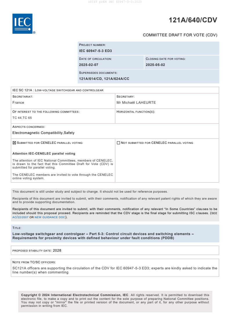
121A/640/CDV
COMMITTEE DRAFT FOR VOTE (CDV)
PROJECT NUMBER:
IEC 60947-5-3 ED3
DATE OF CIRCULATION: CLOSING DATE FOR VOTING:
2025-02-07 2025-05-02
SUPERSEDES DOCUMENTS:
121A/614/CD, 121A/624A/CC
IEC SC 121A : LOW-VOLTAGE SWITCHGEAR AND CONTROLGEAR
SECRETARIAT: SECRETARY:
France Mr Michaël LAHEURTE
OF INTEREST TO THE FOLLOWING COMMITTEES: HORIZONTAL FUNCTION(S):
TC 44,TC 65
ASPECTS CONCERNED:
Electromagnetic Compatibility,Safety
SUBMITTED FOR CENELEC PARALLEL VOTING NOT SUBMITTED FOR CENELEC PARALLEL VOTING
Attention IEC-CENELEC parallel voting
The attention of IEC National Committees, members of CENELEC,
is drawn to the fact that this Committee Draft for Vote (CDV) is
submitted for parallel voting.
The CENELEC members are invited to vote through the CENELEC
online voting system.
This document is still under study and subject to change. It should not be used for reference purposes.
Recipients of this document are invited to submit, with their comments, notification of any relevant patent rights of which they are aware
and to provide supporting documentation.
Recipients of this document are invited to submit, with their comments, notification of any relevant “In Some Countries” clau ses to be
included should this proposal proceed. Recipients are reminded that the CDV stage is the final stage for submitting ISC c lauses. (SEE
AC/22/2007 OR NEW GUIDANCE DOC).
TITLE:
Low-voltage switchgear and controlgear – Part 5-3: Control circuit devices and switching elements –
Requirements for proximity devices with defined behaviour under fault conditions (PDDB)
PROPOSED STABILITY DATE: 2028
NOTE FROM TC/SC OFFICERS:
SC121A officers are supporting the circulation of the CDV for IEC 60947-5-3 ED3; experts are kindly asked to indicate the
line number(s) when commenting
electronic file, to make a copy and to print out the content for the sole purpose of preparing National Committee positions.
You may not copy or "mirror" the file or printed version of the document, or any part of it, for any other purpose without
permission in writing from IEC.
oSIST prEN IEC 60947-5-3:2025
121A/640/CDV – 2 – IEC CDV 60947-5-3 © IEC 2025
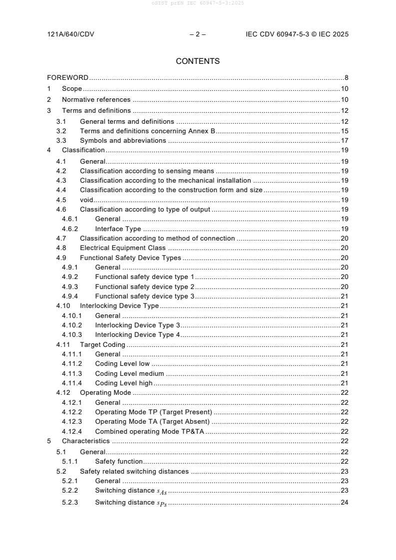
CONTENTS
FOREWORD . 8
1 Scope . 10
2 Normative references . 10
3 Terms and definitions . 12
3.1 General terms and definitions . 12
3.2 Terms and definitions concerning Annex B . 15
3.3 Symbols and abbreviations . 17
4 Classification . 19
4.1 General . 19
4.2 Classification according to sensing means . 19
4.3 Classification according to the mechanical installation . 19
4.4 Classification according to the construction form and size . 19
4.5 void. 19
4.6 Classification according to type of output . 19
4.6.1 General . 19
4.6.2 Interface Type . 19
4.7 Classification according to method of connection . 20
4.8 Electrical Equipment Class . 20
4.9 Functional Safety Device Types . 20
4.9.1 General . 20
4.9.2 Functional safety device type 1 . 20
4.9.3 Functional safety device type 2 . 20
4.9.4 Functional safety device type 3 . 21
4.10 Interlocking Device Type . 21
4.10.1 General . 21
4.10.2 Interlocking Device Type 3. 21
4.10.3 Interlocking Device Type 4. 21
4.11 Target Coding . 21
4.11.1 General . 21
4.11.2 Coding Level low . 21
4.11.3 Coding Level medium . 21
4.11.4 Coding Level high . 21
4.12 Operating Mode . 22
4.12.1 General . 22
4.12.2 Operating Mode TP (Target Present) . 22
4.12.3 Operating Mode TA (Target Absent) . 22
4.12.4 Combined operating Mode TP&TA . 22
5 Characteristics . 22
5.1 General . 22
5.1.1 Safety function. 22
5.2 Safety related switching distances . 23
5.2.1 General . 23
5.2.2 Switching distance s . 23
As
5.2.3 Switching distance s . 24
Ps
oSIST prEN IEC 60947-5-3:2025
IEC CDV 60947-5-3 © IEC 2025 – 3 – 121A/640/CDV
5.2.4 Sensing means with operating range . 25
5.3 Rated and limiting values for the proximity switch and switching element(s) . 25
5.3.1 Voltages . 25
5.3.2 Currents . 26
5.3.3 Rated supply frequency . 26
5.3.4 void . 26
5.3.5 Normal load and abnormal load characteristics . 26
5.3.6 Short-circuit characteristics . 26
5.3.7 OFF-state of the OSSD . 27
5.3.8 Interface Type A0, B0, C0, C1, C2, C3 . 27
5.4 Utilization categories for the switching element . 27
5.5 Safety related characteristics . 28
5.5.1 Proximity device with defined behaviour . 28
5.5.2 Safety integrity . 28
5.6 Electrical Equipment Classes . 29
5.6.1 Electrical Equipment Class III . 29
6 Product information . 29
6.1 Nature of information – Identification . 29
6.2 Marking . 30
6.2.1 General . 30
6.2.2 Terminal identification and marking . 30
6.2.3 Marking of Electrical Equipment Class II . 30
6.2.4 Marking of Electrical Equipment Class III . 30
6.3 Instructions for installation, operation, and maintenance . 30
6.3.1 General . 30
6.3.2 Information for PDDB of Electrical Equipment Class III . 31
6.3.3 Diagnostic test information . 31
6.3.4 Information to the interface types . 31
6.4 Environmental information . 32
6.4.1 Environmentally conscious design process (ECD process) . 32
6.4.2 Procedure to establish material declaration . 32
7 Normal service, mounting and transport conditions . 32
7.1 Normal service conditions . 32
7.2 Conditions during transport and storage . 32
7.3 Mounting . 32
8 Constructional and performance requirements . 32
8.1 Constructional requirements . 32
8.1.1 Materials . 32
8.1.2 Current-carrying parts and their connections . 32
8.1.3 Clearance and creepage distances . 32
8.1.4 Actuation . 32
8.1.5 Void . 33
8.1.6 Void . 33
8.1.7 Terminals . 33
8.1.8 Vacant . 33
8.1.9 Provision for protective earthing . 33
8.1.10 Enclosure Degree of Protection . 33
oSIST prEN IEC 60947-5-3:2025
121A/640/CDV – 4 – IEC CDV 60947-5-3 © IEC 2025
8.1.11 Requirements for proximity switches with integrally connected cables . 33
8.1.12 Electrical Equipment Class II . 33
8.1.13 Chemical stress . 33
8.1.14 Equipment design . 34
8.1.15 Protection against artificial optical radiation . 34
8.1.16 Biological and chemical effects . 34
8.1.17 Unattended operation . 34
8.1.18 Software related security . 34
8.1.19 Requirements for embedded software . 34
8.1.20 Requirements for safety related hardware. 34
8.1.21 Limited energy source . 34
8.2 Performance requirements . 37
8.2.1 Operating conditions . 37
8.2.2 Temperature rise . 42
8.2.3 Dielectric properties . 43
8.2.4 Ability to make and break under normal load and abnormal load
conditions . 43
8.2.5 Conditional short-circuit current . 43
8.2.6 Electromagnetic compatibility (EMC) . 43
8.3 Physical dimensions . 46
8.4 Shock and vibration . 46
8.4.1 Shock . 46
8.4.2 Vibration . 47
8.4.3 Results to be obtained . 47
8.4.4 Special environmental condition – damp heat, salt mist, vibration and
shock . 47
8.5 Fault detection requirements . 47
8.5.1 Faults . 47
8.5.2 Diagnostic . 48
8.5.3 Lock-out Condition . 48
8.6 Measures to influence quantities . 48
9 Tests . 49
9.1 Kind of tests . 49
9.1.1 General . 49
9.1.2 Type tests . 49
9.1.3 Routine tests . 49
9.1.4 Sampling tests . 49
9.2 Compliance with constructional requirements . 49
9.2.1 General . 49
9.2.2 Materials . 50
9.2.3 void . 50
9.2.4 Enclosures for equipment . 50
9.2.5 Mechanical and electrical properties of terminals . 50
9.2.6 indication of the main contact position of the device suitable for
isolation . 50
9.2.7 Limited energy source test . 50
9.2.8 Stored charge energy test . 50
oSIST prEN IEC 60947-5-3:2025
IEC CDV 60947-5-3 © IEC 2025 – 5 – 121A/640/CDV
9.2.9 Conduit pull-out test, torque test and bending test with metallic conduits . 50
9.2.10 Test of earth continuity for protective earth . 50
9.2.11 Breakdown of components . 50
9.2.12 Short-circuit and overload protection of ports . 50
9.2.13 void . 50
9.2.14 Wire flexing test . 50
9.2.15 Artificial optical radiation test . 50
9.3 Performances . 51
9.3.1 Test sequences . 51
9.3.2 General test conditions . 52
9.3.3 Performance under no load, normal load and abnormal load conditions . 54
9.3.4 Performances under short-circuit current conditions . 58
9.3.5 Fault insertion tests . 58
9.4 Verification of the safety related switching distances . 59
9.4.1 General . 59
9.4.2 Switching distance test . 59
9.4.3 Acceptance criteria . 60
9.5 Verification of timing . 61
9.5.1 General . 61
9.5.2 Verification of Turn-on time (t ) . 61
on
9.5.3 Verification of Turn-off time (t ) . 61
off
9.6 Verification of electromagnetic compatibility . 62
9.6.1 General . 62
9.6.2 Immunity . 62
9.6.3 Emission . 62
9.7 Test results and test report . 62
9.8 Ambient temperature variation and humidity. 63
9.8.1 General . 63
9.8.2 Temperature variation . 63
9.8.3 Temperature variation and humidity test . 63
9.8.4 Condensing test . 63
Annex A (informative) Example of a safety related control system. 65
A.1 Description . 65
A.1.1 Safety integrity level requirements, Performance level requirements . 65
A.1.2 Conditions of use . 65
A.2 Realization . 66
A.3 Collection of data . 66
A.4 Quantitative Calculation . 67
A.5 Results . 69
Annex B (informative) Classification of Binary Interfaces – Functional Safety aspects
covered by dynamic testing . 70
B.1 General . 70
B.2 Minimum information on compatibility to be provided in the product
documentation . 70
B.2.1 General . 70
B.2.2 Basic electrical parameters . 70
B.2.3 Structure of the identifying key for a PDDB . 70
oSIST prEN IEC 60947-5-3:2025
121A/640/CDV – 6 – IEC CDV 60947-5-3 © IEC 2025
B.3 Characteristics of interface type A0 . 71
B.3.1 General . 71
B.3.2 Static characteristics of interface type A0 . 72
B.3.3 Dynamic characteristics of interface type A0 . 72
B.3.4 Product information to be supplied in the product documentation . 72
B.4 Characteristics of interface type B0 . 73
B.4.1 General . 73
B.4.2 Static characteristics of interface type B0 . 73
B.4.3 Dynamic characteristics of interface type B0 . 73
B.4.4 Product information to be supplied in the product documentation . 75
B.5 Characteristics of interface type C . 75
B.5.1 General . 75
B.5.2 Static characteristics of interface type C . 76
B.5.3 Dynamic characteristics of interface type C . 76
B.5.4 Classification of interface type C. 76
B.5.5 Product information to be supplied in the product documentation . 78
Annex C (informative) Catalogue of single faults affecting the electrical equipment of
the PDDB . 80
C.1 General . 80
C.2 Conductors and connectors . 80
C.3 Switches . 80
C.4 Discrete electrical components . 80
C.5 Solid-state electrical components . 80
Annex D (informative) Void . 81
Annex E (informative) Product Information . 82
E.1 General . 82
Bibliography . 85
Figure 1 – Absent and Present switching distance s and s for a PDDB with
As P
Operating Mode TP (Target Present) . 24
Figure 2 – Absent and Present switching distance s and s for a PDDB with
A Ps
Operating Mode TA (Target Absent) . 25
Figure 3 – Characteristics of the absent switching distance . 37
Figure 4 – Characteristics of the present switching distance . 38
Figure 5 – Voltages and Current Characteristics . 54
Figure 6 – Test circuit diagram for the detection of fault stuck@high . 56
Figure A.1 – Position monitoring of movable guards for the prevention of hazardous
movements . 66
Figure A.2 – Safety-related block diagram of the safety related function . 67
Figure B.1 – Interface type A0 . 71
Figure B.2 – Interface type B0 . 73
Figure B.3 – Test pulse delay ∆t much smaller than test pulse duration t . 74
i i
Figure B.4 – Test pulse delay ∆t greater than test pulse duration t . 74
i i
Figure B.5 – Interface type C . 75
Figure B.6 – Dynamic behaviour interface type C . 78
oSIST prEN IEC 60947-5-3:2025
IEC CDV 60947-5-3 © IEC 2025 – 7 – 121A/640/CDV
Table 1 – Symbols and abbreviations . 17
Table 2 – Interface types of PDDBs . 19
Table 3 – Operating Modes of PDDBs . 22
Table 4 – Static Characteristics of Interface Types A0, B0, C0, C1, C2 and C3 . 27
Table 5 – Dynamic Characteristics of Interface Types A0, B0, C0, C1, C2 and C3 . 27
Table 6 – Characteristic safety values of functional safety device types . 29
Table 7 – Product Information on Interface Types A0, B0, C0, C1, C2 and C3 . 31
Table 8 – Limits for limited energy sources without an overcurrent protective device . 35
Table 9 – Limits for limited energy sources with an overcurrent protective device . 36
Table 10 – Limits for limited energy source with limited current impedance . 36
Table 11 – Characteristics of the absent switching distance . 38
Table 12 – Characteristics of the present switching distance. 38
Table 13 – Operating Voltages of 24 V solid state OSSD . 42
Table 14 – Reaction of PDDB during test . 44
Table 15 – Immunity test requirements for PDDBs . 45
Table 16 – Acceptance criteria for s . 60
Ai
Table 17 – Acceptance criteria for s . 61
Pi
Table A.1 – Collection of safety related reliability . 66
Table B.1 – Basic electrical parameters . 70
Table B.2 – Product information interface type A0 – Source . 72
Table B.3 – Product information interface type A0 – Sink . 72
Table B.4 – Product information interface type B0 – source . 75
Table B.5 – Product information interface type B0 – sink . 75
Table B.6 – Classification for interface type C . 77
Table B.7 – Product information interface type C – Source . 78
Table B.8 – Product information interface type C – Sink . 79
Table E.1 – Product Information . 82
oSIST prEN IEC 60947-5-3:2025
121A/640/CDV – 8 – IEC CDV 60947-5-3 © IEC 2025
INTERNATIONAL ELECTROTECHNICAL COMMISSION
____________
LOW-VOLTAGE SWITCHGEAR AND CONTROLGEAR –
Part 5-3: Control circuit devices and switching elements –
Requirements for proximity devices
with defined behaviour under fault conditions (PDDB)
FOREWORD
1) The International Electrotechnical Commission (IEC) is a worldwide organization for standardization comprising
all national electrotechnical committees (IEC National Committees). The object of IEC is to promote international
co-operation on all questions concerning standardization in the electrical and electronic fields. To this end and
in addition to other activities, IEC publishes International Standards, Technical Specifications, Technical Reports,
Publicly Available Specifications (PAS) and Guides (hereafter referred to as “IEC Publication(s)”). Their
preparation is entrusted to technical committees; any IEC National Committee interested in the subject dealt with
may participate in this preparatory work. International, governmental and non-governmental organizations liaising
with the IEC also participate in this preparation. IEC collaborates closely with the International Organization for
Standardization (ISO) in accordance with conditions determined by agreement between the two organizations.
2) The formal decisions or agreements of IEC on technical matters express, as nearly as possible, an international
consensus of opinion on the relevant subjects since each technical committee has representation from all
interested IEC National Committees.
3) IEC Publications have the form of recommendations for international use and are accepted by IEC National
Committees in that sense. While all reasonable efforts are made to ensure that the technical content of IEC
Publications is accurate, IEC cannot be held responsible for the way in which they are used or for any
misinterpretation by any end user.
4) In order to promote international uniformity, IEC National Committees undertake to apply IEC Publications
transparently to the maximum extent possible in their national and regional publications. Any divergence between
any IEC Publication and the corresponding national or regional publication shall be clearly indicated in the latter.
5) IEC itself does not provide any attestation of conformity. Independent certification bodies provide conformity
assessment services and, in some areas, access to IEC marks of conformity. IEC is not responsible for any
services carried out by independent certification bodies.
6) All users should ensure that they have the latest edition of this publication.
7) No liability shall attach to IEC or its directors, employees, servants or agents including individual experts and
members of its technical committees and IEC National Committees for any personal injury, property damage or
other damage of any nature whatsoever, whether direct or indirect, or for costs (including legal fees) and
expenses arising out of the publication, use of, or reliance upon, this IEC Publication or any other IEC
Publications.
8) Attention is drawn to the Normative references cited in this publication. Use of the referenced publications is
indispensable for the correct application of this publication.
9) Attention is drawn to the possibility that some of the elements of this IEC Publication may be the subject of patent
rights. IEC shall not be held responsible for identifying any or all such patent rights.
International Standard IEC 60947-5-3 has been prepared by subcommittee SC121A:
Low-voltage switchgear and controlgear, of IEC technical committee 121: Switchgear and
controlgear and their assemblies for low voltage.
This third edition includes the following significant technical changes with respect to the
previous edition:
– Update of the scope, refined fault performance aspects and relation to standards of
functional safety.
– The ‘safe state’ is generally determined as ‘OFF-state’ (see 3.1.8).
– Update of EMC requirements in clause 8.2.6 with references to IEC 60947-5-2 for
acceptance criteria A, B and C and requirements of Table 15 for acceptance criterion DS.
– Interface types for binary interfaces are introduced. (See 4.6.2 and Annex B).
oSIST prEN IEC 60947-5-3:2025
IEC CDV 60947-5-3 © IEC 2025 – 9 – 121A/640/CDV
– Functional safety device types according to ISO 13849-1:2022 Annex O (See 4.9).
– Interlocking device type and coding level according to ISO 14119 are adapted (see 4.10 and
4.11).
– The operating modes Target Present (4.12.2) and Target Absent (4.12.3) are introduced.
– The ‘switching distance’ replaces the terms ‘release’ and ‘operating’. The behaviour of the
PDDB is described according to the operating mode (clause 4.12).
– The context and verification of the switching distances are considered according to ISO/IEC
Guide 98-3:2008 (GUM) and IEC TR 6xxxxx:2025 (See 8.2.1.3 and 9.4.2).
– Requirements for electrical equipment class III are refined.
– The risk time is replaced with the safety response time (3.1.11).
– Annex A gives a new example of safety related control system.
– The test sequences (see 9.3.1) are updated for the specific behaviour of a PDDB.
This standard is to be read in conjunction with IEC 60947-1, Low voltage switchgear and
controlgear – Part 1: General rules and IEC 60947-5-2, Low-voltage switchgear and controlgear
– Part 5-2: Control circuit devices and switching elements – Proximity switches. The provisions
of Part 1 and Part 5-2 are only applicable to this standard where specifically called for. The
numbering of the subclauses of this standard is sometimes not continuous because it is based
on the numbering of the subclauses of IEC 60947-1 or IEC 60947-5-2.
The text of this standard is based on the following documents:
FDIS Report on voting
xxx xxx
Full information on the voting for the approval of this standard can be found in the report on
voting indicated in the above table.
This publication has been drafted in accordance with the ISO/IEC Directives, Part 2.
A list of all parts in the IEC 60947 series, published under the general title Low-voltage
switchgear and controlgear, can be found on the IEC website.
The committee has decided that the contents of this publication will remain unchanged until the
stability date indicated on the IEC web site under "http://webstore.iec.ch" in the data related to
the specific publication. At this date, the publication will be
• reconfirmed,
• withdrawn,
• replaced by a revised edition, or
• amended.
oSIST prEN IEC 60947-5-3:2025
121A/640/CDV – 10 – IEC CDV 60947-5-3 © IEC 2025
1 LOW-VOLTAGE SWITCHGEAR AND CONTROLGEAR –
3 Part 5-3: Control circuit devices and switching elements –
4 Requirements for proximity devices
5 with defined behaviour under fault conditions (PDDB)
9 1 Scope
10 This part of IEC 60947 series provides additional requirements to those given in
11 IEC 60947-5-2 and IEC 60947-5-1:2024 Annex D (reed contact magnetic switches). It
12 addresses the fault performance aspects of proximity devices with a defined behaviour under
13 fault conditions (PDDB). It does not address any other characteristics that can be required for
14 specific applications.
15 This document does not apply to protective equipment to directly detect the presence of
16 persons, that are covered by IEC 61496 series or IEC/TS 62998 series.
17 NOTE A PDDB device can be used to detect indirectly the presence of a person, for example by detecting the
18 position of a platform on which the operator stands (example, garbage trucks).
19 This product standard does not specify requirements for the analogue output of PDDB, if any.
20 This product standard does not deal with any specific requirements on acoustic noise as the
21 noise emission of proximity devices is not considered to be a relevant hazard.
22 A PDDB product is intended to be used as sensing subsystem of a safety related control system
23 according to IEC 62061 or ISO 13849-1. Depending on construction principles and complexity,
24 this standard is based on product development of IEC 61508 series in order to meet the product
25 specific requirements of IEC 61508 series, IEC 62061 and/or ISO 13849 series.
26 NOTE The Functional Safety Device Type classification regarding functional safety correlates with IEC 62683-2-3 DB.
27 This standard includes requirements for PDDBs when designed for use as part of an interlocking
28 devices according to ISO 14119.
29 This document does not consider aspects of:
30 – software updates and self-evolving behaviour
31 – explosive atmospheres
32 2 Normative references
33 The following documents are referred to in the text in such a way that some or all of their content
34 constitutes requirements of this document. For dated references, only the edition cited applies.
35 For undated references, the latest edition of the referenced document (including any
36 amendments) applies.
37 IEC 60068-2-1:2007, Environmental testing – Part 2-1: Tests – Test A: Cold
38 IEC 60068-2-30:2005, Environmental testing – Part 2-30: Tests – Test Db: Damp heat, cyclic
39 (12 + 12 h cycle)
oSIST prEN IEC 60947-5-3:2025
IEC CDV 60947-5-3 © IEC 2025 – 11 – 121A/640/CDV
40 IEC 60204-1:2016, Safety of machinery – Electrical equipment of machines – Part 1: General
41 requirements
42 IEC 60529:1989+AMD1:1999+AMD2:2013 CSV, Degrees of protection provided by enclosures
43 (IP Code)
44 IEC 60812:2018, Failure modes and effects analysis (FMEA and FMEDA)
45 IEC 60947-1:2020, Low-voltage switchgear and controlgear – Part 1: General rules
46 IEC 60947-5-1:2016, Low-voltage switchgear and controlgear – Part 5-1: Control circuit devices
47 and switching elements – Electromechanical control circuit devices
48 IEC 60947-5-2:2019, Low-voltage switchgear and controlgear – Part 5-2: Control circuit devices
49 and switching elements – Proximity switches
50 IEC 61000-4-2:2008, Electromagnetic compatibility (EMC) – Part 4-2: Testing and
51 measurement techniques – Electrostatic discharge immunity test
52 IEC 61000-4-3:2020, Electromagnetic compatibility (EMC) – Part 4-3: Testing and
53 measurement techniques – Radiated, radio-frequency, electromagnetic field immunity test
54 IEC 61000-4-4:2012, Electromagnetic compatibility (EMC) – Part 4-4: Testing and
55 measurement techniques – Electrical fast transient/burst immunity test
56 IEC 61000-4-5:2014+AMD1:2017 CSV, Electromagnetic compatibility (EMC) – Part 4-5: Te
...