

IEC 61514-2:2026
(Main)Industrial process control systems - Methods of evaluating the performance of valve positioners with pneumatic outputs - Part 2: Test Methods for intelligent positioners mounted on an actuator valve assembly
- Abstract
IEC 61514-2:2026 specifies design reviews and tests intended to measure and determine the static and dynamic performance, the degree of intelligence and the communication capabilities of single-acting or double-acting intelligent valve positioners. The tests can be applied to positioners which receive standard analogue electrical input signals (as specified in IEC 60381-1 or IEC 60381-2) and/or digital signals via a data communication link (for example Fieldbus) and have a pneumatic output. An intelligent valve positioner as defined in Clause 3 is an instrument that uses for performing its functions digital techniques for data processing, decision-making and bi-directional communication. It can be equipped with additional sensors and additional functionality supporting the main function. The performance testing of an intelligent valve positioner is conducted with the positioner mounted on and connected to the actuator/valve assembly the positioner is used on. The specific characteristic parameters of the actuator/valve combination such as size, stroke, friction, type of packing, spring package and supply pressure for the pneumatic part has significant impact on the performance of a positioner. The methods of evaluation given in this document are intended for testing laboratories to verify equipment performance specifications. The manufacturers of intelligent positioners are urged to apply this document at an early stage of development.
This document is intended to provide guidance for designing evaluations of intelligent valve positioners by providing:
- a checklist for reviewing their hardware and software design in a structured way;
- test methods for measuring and qualifying their performance under various environmental and operational conditions;
- methods for reporting the data obtained.
When a full evaluation, in accordance with this document, is not required or possible, the tests which are required are performed and the results reported in accordance with the relevant clauses of this document. In such cases, the test report will state that it does not cover the full number of tests specified herein. Furthermore, the items omitted are mentioned, to give the reader of the report a clear overview. This document is also applicable for non-intelligent microprocessor-based valve positioners without means for bi-directional communication. In that case an evaluation will be reduced to a limited programme of performance testing and a review of the construction. This third edition cancels and replaces the second edition published in 2013. This edition constitutes a technical revision.
This edition includes the following significant technical changes with respect to the previous edition:
a) in 5.5.2, the standard for the measurements of influence quantities has been changed to IEC 62828-1:2026;
b) all references to IEC 61514 have been updated to IEC 61514:2026;
c) the aspect of cyber-security has been added in 4.2.7 and 4.2.9.
This document is to be used in conjunction with IEC 61514:2026.
- Status
- Published
- Publication Date
- 06-Aug-2026
- Technical Committee
- SC 65B - Measurement and control devices
- Drafting Committee
- WG 6 - TC 65/SC 65B/WG 6
- Current Stage
- PPUB - Publication issued
- Start Date
- 07-Aug-2026
- Completion Date
- 17-Jul-2026
Buy Documents
IEC 61514-2:2026 - Industrial process control systems - Methods of evaluating the performance of valve positioners with pneumatic outputs - Part 2: Test Methods for intelligent positioners mounted on an actuator valve assembly
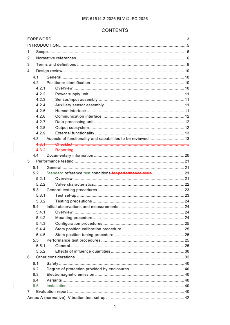
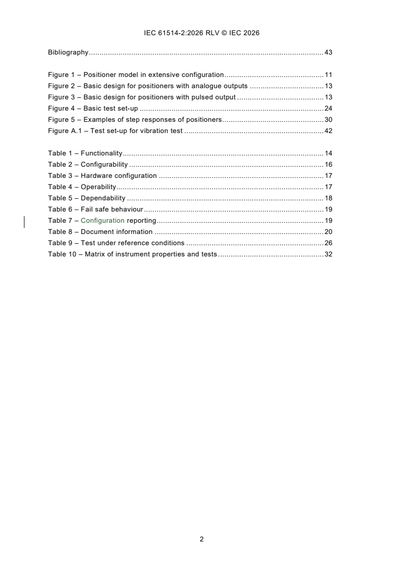
REDLINE IEC 61514-2:2026 RLV - Industrial process control systems - Methods of evaluating the performance of valve positioners with pneumatic outputs - Part 2: Test Methods for intelligent positioners mounted on an actuator valve assembly
IEC 61514-2:2026 - Systemes de commande des processus industriels - Méthodes d'évaluation des performances des positionneurs de vanne a sorties pneumatiques - Partie 2: Méthodes d’essai pour positionneurs intelligents<br /> montés sur un ensemble actionneur/vanne
IEC 61514-2:2026 is an International Standard from the IEC for evaluating the performance of intelligent valve positioners with pneumatic outputs. It specifies design reviews and test methods for single-acting and double-acting positioners that use analogue input signals, digital communication, or both, and it is aimed at testing laboratories and manufacturers working with actuator/valve assemblies.
What does IEC 61514-2:2026 specify?
IEC 61514-2:2026 defines how to review, test and report the performance of intelligent valve positioners mounted on the actuator/valve assembly in which they will be used. The document covers the positioner itself, its communication and auxiliary functions, and the way results are reported.
The standard is organized into seven clauses:
- Scope
- Normative references
- Terms and definitions
- Design review
- Performance testing
- Other considerations
- Evaluation report
| Annex | What it covers |
|---|---|
| Annex A (normative) | Vibration test set-up for intelligent positioners |
The scope also extends to non-intelligent microprocessor-based valve positioners without bi-directional communication, but in a reduced evaluation programme.
What are the key requirements of IEC 61514-2:2026?
Design review: what the evaluator must identify
IEC 61514-2:2026 asks for a structured review of the hardware and software design before testing starts. Clause 4 uses checklists and documentation review to make the positioner’s physical structure and functions explicit, which helps the evaluator see what can and cannot be tested.
- Clause 4.2 requires identification of the main modules, including power supply, sensor/input assembly, auxiliary sensors, human interface, communication interface, data processing unit, output subsystem and external functionality. In practice, this means the report should show how the positioner is built and how it connects to the valve, the field, and any host system.
- Clause 4.3 uses tables 1 to 7 to check functionality, configurability, hardware configuration, operability, dependability, fail-safe behaviour and configuration reporting. This matters because the standard is not only about accuracy - it also checks how the positioner is configured, protected, diagnosed and operated.
- Clause 4.4 requires documentary information such as identification, operating principle, environmental limits, safety data, software and firmware versions, mounting instructions, configuration instructions, maintenance instructions and performance specifications. For a buyer or lab, this is the evidence base for comparing products and for writing a complete report.
Performance testing: what is measured and under which conditions
IEC 61514-2:2026 says that testing is done with the positioner mounted on the actual actuator/valve assembly, because stroke, friction, packing, spring package and supply pressure strongly affect performance. That is important in practice: results are meaningful only when the test assembly reflects the intended use.
- Clause 5.2 sets the reference test conditions and requires the relevant actuator/valve parameters to be documented. When different makes are compared, they should be tested on identical assemblies so that the comparison is fair.
- Clause 5.3 defines the test set-up, including travel measurement, input signal generation, auxiliary inputs and auxiliary outputs. The practical point is that measurement uncertainty has to be better than the effect being assessed, or the result is not useful.
- Clause 5.4 covers initial observations, mounting, configuration, stem position calibration and stem position tuning. These steps are not just administrative - they reveal how easy the positioner is to install, commission and return to service.
- Clause 5.5.1 lists the core performance tests: inaccuracy, non-linearity, hysteresis, repeatability, switching points for digital inputs, dead band, balance pressure, frequency response, step response, airflow, steady-state air consumption and power requirements. These are the measures that show how the positioner behaves in steady operation and during movement.
- Clause 5.5.2 extends testing to influence quantities such as supply pressure, ambient temperature, humidity, mounting position, rough handling, mechanical vibration, magnetic field, radiated RF, conducted RF, electrical transients, surge, electrostatic discharges, power interruptions, start-up drift, long-term drift, accelerated life and air leakage. In practice, this tells the user how the instrument reacts to environment, disturbance and ageing.
- Annex A makes the vibration test set-up mandatory and ties it to the mechanical vibration procedure in Clause 5.5.2. That matters because vibration behaviour depends on how the assembly is mounted and measured.
Safety, reporting and practical use
Clause 6 points the user to safety, enclosure protection, electromagnetic emission, variants and installation. For electrically powered units, the document refers to electrical shock protection, hazardous-area certification and functional safety data where applicable.
Clause 7 requires an evaluation report prepared in accordance with IEC 62828-1 and supported by detailed information on the positioner, actuator/valve assembly, test set-up, equipment used, input/output data and supply conditions. The laboratory must keep the original measurement documentation for at least two years after the report is issued.
What terms does IEC 61514-2:2026 define?
- intelligent valve positioner - A microprocessor-based position controller that uses digital data processing, decision-making and bi-directional communication to control valve travel.
- configuring - The process of implementing the functionality needed for a specific application.
- configurability - The extent to which an intelligent positioner can be provided with functions for different applications.
- calibration - The process of adjusting travel range to the required value for a defined input-to-travel characteristic.
- tuning - The process of adjusting control parameters for a particular application.
- set-up - The combined process of configuring, calibrating and tuning a positioner for a specific actuator/valve assembly.
- dead band - The finite range in which a change in input does not produce a measurable change in output.
- balance pressure - The average pressure on the opposite chambers of a double acting actuator in steady state, used here as an indicator of stiffness.
Who uses IEC 61514-2:2026?
IEC 61514-2:2026 is used by testing laboratories that verify equipment performance specifications for valve positioners. It is also used by manufacturers during early development, because it gives a structured way to review hardware and software, set up test programmes and write reports.
The document is relevant to engineers and quality personnel working with industrial-process measurement, control and automation, especially where actuator/valve assemblies, fieldbus communication, diagnostics, safety functions, and environmental or EMC testing are involved. It is also useful for teams preparing technical documentation for commissioning, maintenance, troubleshooting and product comparison.
What changed in IEC 61514-2:2026 from the previous edition?
IEC 61514-2:2026 is the third edition and replaces the second edition published in 2013. The document states three significant technical changes:
- the standard for measurements of influence quantities in 5.5.2 is changed to IEC 62828-1:2026
- references to IEC 61514 are updated to IEC 61514:2026
- cyber-security is added in 4.2.7 and 4.2.9
Which standards are used with IEC 61514-2:2026?
| Standard | What it contributes |
|---|---|
| IEC 61514:2026 | The companion part used together with IEC 61514-2:2026 |
| IEC 62828-1:2026 | Reference conditions and report preparation for several performance and influence tests |
| IEC 60381-1, IEC 60381-2 | Standard analogue input signals for process control systems |
| IEC 60068-2-1, IEC 60068-2-2, IEC 60068-2-6, IEC 60068-2-31, IEC 60068-2-78 | Environmental test methods for cold, dry heat, vibration, rough handling shocks and damp heat |
| IEC 60529, IEC 61032 | Degrees of protection and probe checks for enclosures |
| IEC 61010-1 | Electrical safety requirements for measurement, control and laboratory use |
| IEC 61326-1:2020 | EMC requirements and immunity/emission-related tests |
| IEC 61508, IEC 61511, IEC 62061 | Functional safety and safety-related control-system requirements |
| IEC 60534-1 | Control valve terminology and inherent characteristic terms used in the document |
| IEC 60079 | Requirements for explosive atmospheres |
| IEC 60654, IEC 60721-3 | Operating and environmental condition classifications |
| IEC 60050-300, IEC 60050-351 | Vocabulary used for measurements and control technology |
What does the IEC 61514-2:2026 document contain?
IEC 61514-2:2026 contains a design-review framework, detailed test procedures, and reporting guidance for intelligent valve positioners. The body of the standard includes tables that act as checklists for functionality, configurability, hardware configuration, operability, dependability, fail-safe behaviour, configuration reporting and document information.
The performance section includes figures for the basic test set-up, step responses and vibration set-up, plus a matrix of influence-quantity tests. It also includes a formula-based evaluation for the equal percentage characteristic, but without turning the document into a single-product recipe: the evaluator still has to select the actuator/valve assembly, configuration and operating conditions and then record the resulting behaviour.
Relations
- Effective Date
- 05-Sep-2023
Buy Documents
IEC 61514-2:2026 - Industrial process control systems - Methods of evaluating the performance of valve positioners with pneumatic outputs - Part 2: Test Methods for intelligent positioners mounted on an actuator valve assembly
REDLINE IEC 61514-2:2026 RLV - Industrial process control systems - Methods of evaluating the performance of valve positioners with pneumatic outputs - Part 2: Test Methods for intelligent positioners mounted on an actuator valve assembly
IEC 61514-2:2026 - Systemes de commande des processus industriels - Méthodes d'évaluation des performances des positionneurs de vanne a sorties pneumatiques - Partie 2: Méthodes d’essai pour positionneurs intelligents<br /> montés sur un ensemble actionneur/vanne
Get Certified
Connect with accredited certification bodies for this standard

DVS-ZERT GmbH
German welding certification society.
Institut za varilstvo d.o.o. (Welding Institute)
Slovenia's leading welding institute since 1952. ISO 3834, EN 1090, pressure equipment certification, NDT personnel, welder qualification. Only IIW Au
CARES (UK Certification Authority for Reinforcing Steels)
UK certification for reinforcing steels and construction.
Sponsored listings
Frequently Asked Questions
IEC 61514-2:2026 is a standard published by the International Electrotechnical Commission (IEC). Its full title is "Industrial process control systems - Methods of evaluating the performance of valve positioners with pneumatic outputs - Part 2: Test Methods for intelligent positioners mounted on an actuator valve assembly". This standard covers: IEC 61514-2:2026 specifies design reviews and tests intended to measure and determine the static and dynamic performance, the degree of intelligence and the communication capabilities of single-acting or double-acting intelligent valve positioners. The tests can be applied to positioners which receive standard analogue electrical input signals (as specified in IEC 60381-1 or IEC 60381-2) and/or digital signals via a data communication link (for example Fieldbus) and have a pneumatic output. An intelligent valve positioner as defined in Clause 3 is an instrument that uses for performing its functions digital techniques for data processing, decision-making and bi-directional communication. It can be equipped with additional sensors and additional functionality supporting the main function. The performance testing of an intelligent valve positioner is conducted with the positioner mounted on and connected to the actuator/valve assembly the positioner is used on. The specific characteristic parameters of the actuator/valve combination such as size, stroke, friction, type of packing, spring package and supply pressure for the pneumatic part has significant impact on the performance of a positioner. The methods of evaluation given in this document are intended for testing laboratories to verify equipment performance specifications. The manufacturers of intelligent positioners are urged to apply this document at an early stage of development. This document is intended to provide guidance for designing evaluations of intelligent valve positioners by providing: - a checklist for reviewing their hardware and software design in a structured way; - test methods for measuring and qualifying their performance under various environmental and operational conditions; - methods for reporting the data obtained. When a full evaluation, in accordance with this document, is not required or possible, the tests which are required are performed and the results reported in accordance with the relevant clauses of this document. In such cases, the test report will state that it does not cover the full number of tests specified herein. Furthermore, the items omitted are mentioned, to give the reader of the report a clear overview. This document is also applicable for non-intelligent microprocessor-based valve positioners without means for bi-directional communication. In that case an evaluation will be reduced to a limited programme of performance testing and a review of the construction. This third edition cancels and replaces the second edition published in 2013. This edition constitutes a technical revision. This edition includes the following significant technical changes with respect to the previous edition: a) in 5.5.2, the standard for the measurements of influence quantities has been changed to IEC 62828-1:2026; b) all references to IEC 61514 have been updated to IEC 61514:2026; c) the aspect of cyber-security has been added in 4.2.7 and 4.2.9. This document is to be used in conjunction with IEC 61514:2026.
IEC 61514-2:2026 specifies design reviews and tests intended to measure and determine the static and dynamic performance, the degree of intelligence and the communication capabilities of single-acting or double-acting intelligent valve positioners. The tests can be applied to positioners which receive standard analogue electrical input signals (as specified in IEC 60381-1 or IEC 60381-2) and/or digital signals via a data communication link (for example Fieldbus) and have a pneumatic output. An intelligent valve positioner as defined in Clause 3 is an instrument that uses for performing its functions digital techniques for data processing, decision-making and bi-directional communication. It can be equipped with additional sensors and additional functionality supporting the main function. The performance testing of an intelligent valve positioner is conducted with the positioner mounted on and connected to the actuator/valve assembly the positioner is used on. The specific characteristic parameters of the actuator/valve combination such as size, stroke, friction, type of packing, spring package and supply pressure for the pneumatic part has significant impact on the performance of a positioner. The methods of evaluation given in this document are intended for testing laboratories to verify equipment performance specifications. The manufacturers of intelligent positioners are urged to apply this document at an early stage of development. This document is intended to provide guidance for designing evaluations of intelligent valve positioners by providing: - a checklist for reviewing their hardware and software design in a structured way; - test methods for measuring and qualifying their performance under various environmental and operational conditions; - methods for reporting the data obtained. When a full evaluation, in accordance with this document, is not required or possible, the tests which are required are performed and the results reported in accordance with the relevant clauses of this document. In such cases, the test report will state that it does not cover the full number of tests specified herein. Furthermore, the items omitted are mentioned, to give the reader of the report a clear overview. This document is also applicable for non-intelligent microprocessor-based valve positioners without means for bi-directional communication. In that case an evaluation will be reduced to a limited programme of performance testing and a review of the construction. This third edition cancels and replaces the second edition published in 2013. This edition constitutes a technical revision. This edition includes the following significant technical changes with respect to the previous edition: a) in 5.5.2, the standard for the measurements of influence quantities has been changed to IEC 62828-1:2026; b) all references to IEC 61514 have been updated to IEC 61514:2026; c) the aspect of cyber-security has been added in 4.2.7 and 4.2.9. This document is to be used in conjunction with IEC 61514:2026.
IEC 61514-2:2026 is classified under the following ICS (International Classification for Standards) categories: 23.060.99 - Other valves; 25.040.40 - Industrial process measurement and control. The ICS classification helps identify the subject area and facilitates finding related standards.
IEC 61514-2:2026 has the following relationships with other standards: It is inter standard links to IEC 61514-2:2013. Understanding these relationships helps ensure you are using the most current and applicable version of the standard.
IEC 61514-2:2026 is available in PDF format for immediate download after purchase. The document can be added to your cart and obtained through the secure checkout process. Digital delivery ensures instant access to the complete standard document.
Standards Content (Sample)
IEC 61514-2 ®
Edition 3.0 2026-08
INTERNATIONAL
STANDARD
Industrial process control systems - Methods of evaluating the performance of
valve positioners with pneumatic outputs -
Part 2: Test Methods for intelligent positioners mounted on an actuator valve
assembly
ICS 23.060.99; 25.040.40 ISBN 978-2-8327-1339-6
All rights reserved. Unless otherwise specified, no part of this publication may be reproduced or utilized in any form or
by any means, electronic or mechanical, including photocopying and microfilm, without permission in writing from either
IEC or IEC's member National Committee in the country of the requester. If you have any questions about IEC copyright
or have an enquiry about obtaining additional rights to this publication, please contact the address below or your local
IEC member National Committee for further information.
IEC Secretariat Tel.: +41 22 919 02 11
3, rue de Varembé info@iec.ch
CH-1211 Geneva 20 www.iec.ch
Switzerland
About the IEC
The International Electrotechnical Commission (IEC) is the leading global organization that prepares and publishes
International Standards for all electrical, electronic and related technologies.
About IEC publications
The technical content of IEC publications is kept under constant review by the IEC. Please make sure that you have the
latest edition, a corrigendum or an amendment might have been published.
IEC publications search - IEC Products & Services Portal - products.iec.ch
webstore.iec.ch/advsearchform Discover our powerful search engine and read freely all the
The advanced search enables to find IEC publications by a publications previews, graphical symbols and the glossary.
variety of criteria (reference number, text, technical With a subscription you will always have access to up to date
committee, …). It also gives information on projects, content tailored to your needs.
replaced and withdrawn publications.
Electropedia - www.electropedia.org
The world's leading online dictionary on electrotechnology,
IEC Just Published - webstore.iec.ch/justpublished
Stay up to date on all new IEC publications. Just Published containing more than 22 500 terminological entries in English
details all new publications released. Available online and and French, with equivalent terms in 25 additional languages.
once a month by email. Also known as the International Electrotechnical Vocabulary
(IEV) online.
IEC Customer Service Centre - webstore.iec.ch/csc
If you wish to give us your feedback on this publication or
need further assistance, please contact the Customer
Service Centre: sales@iec.ch.
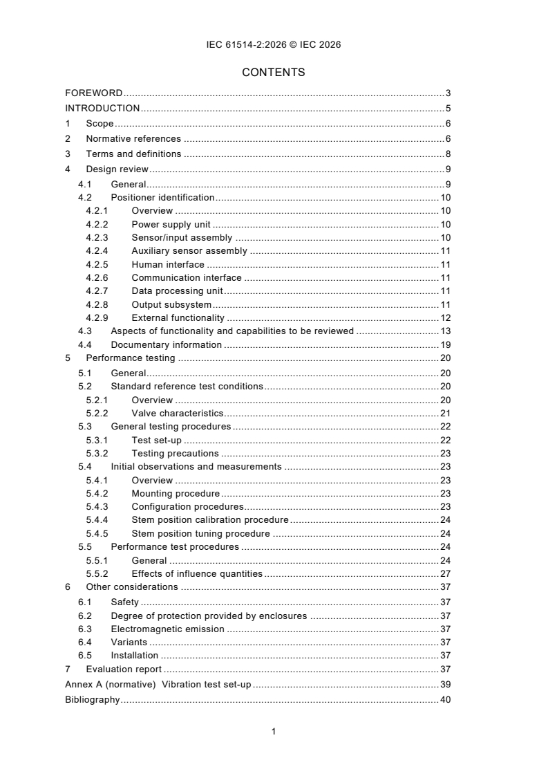
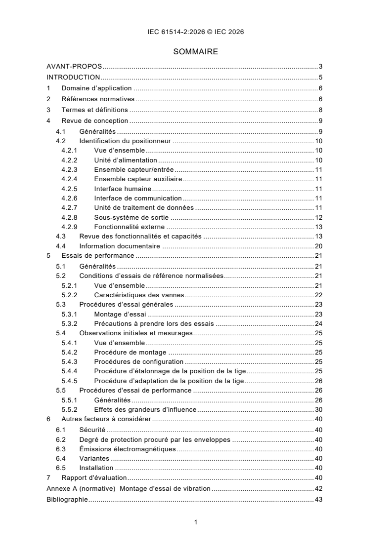
CONTENTS
FOREWORD . 3
INTRODUCTION . 5
1 Scope . 6
2 Normative references . 6
3 Terms and definitions . 8
4 Design review . 9
4.1 General . 9
4.2 Positioner identification . 10
4.2.1 Overview . 10
4.2.2 Power supply unit . 10
4.2.3 Sensor/input assembly . 10
4.2.4 Auxiliary sensor assembly . 11
4.2.5 Human interface . 11
4.2.6 Communication interface . 11
4.2.7 Data processing unit . 11
4.2.8 Output subsystem . 11
4.2.9 External functionality . 12
4.3 Aspects of functionality and capabilities to be reviewed . 13
4.4 Documentary information . 19
5 Performance testing . 20
5.1 General . 20
5.2 Standard reference test conditions . 20
5.2.1 Overview . 20
5.2.2 Valve characteristics. 21
5.3 General testing procedures . 22
5.3.1 Test set-up . 22
5.3.2 Testing precautions . 23
5.4 Initial observations and measurements . 23
5.4.1 Overview . 23
5.4.2 Mounting procedure . 23
5.4.3 Configuration procedures. 23
5.4.4 Stem position calibration procedure . 24
5.4.5 Stem position tuning procedure . 24
5.5 Performance test procedures . 24
5.5.1 General . 24
5.5.2 Effects of influence quantities . 27
6 Other considerations . 37
6.1 Safety . 37
6.2 Degree of protection provided by enclosures . 37
6.3 Electromagnetic emission . 37
6.4 Variants . 37
6.5 Installation . 37
7 Evaluation report . 37
Annex A (normative) Vibration test set-up . 39
Bibliography . 40
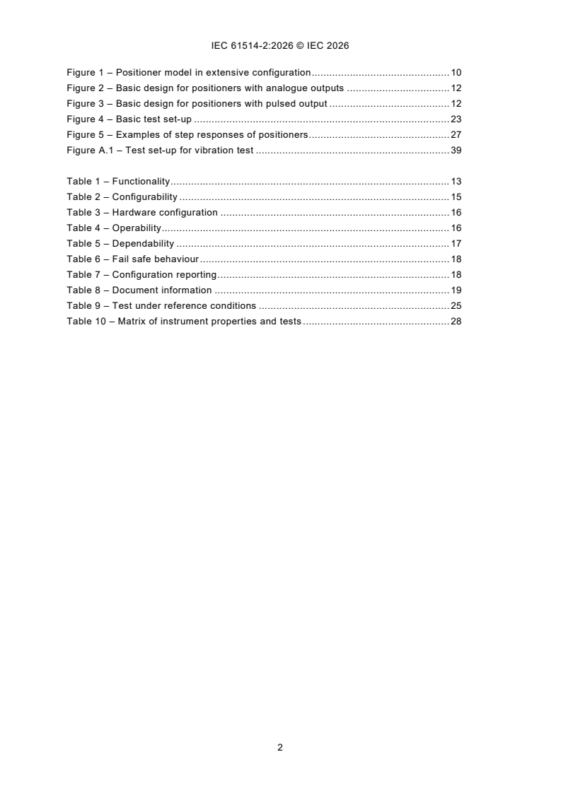
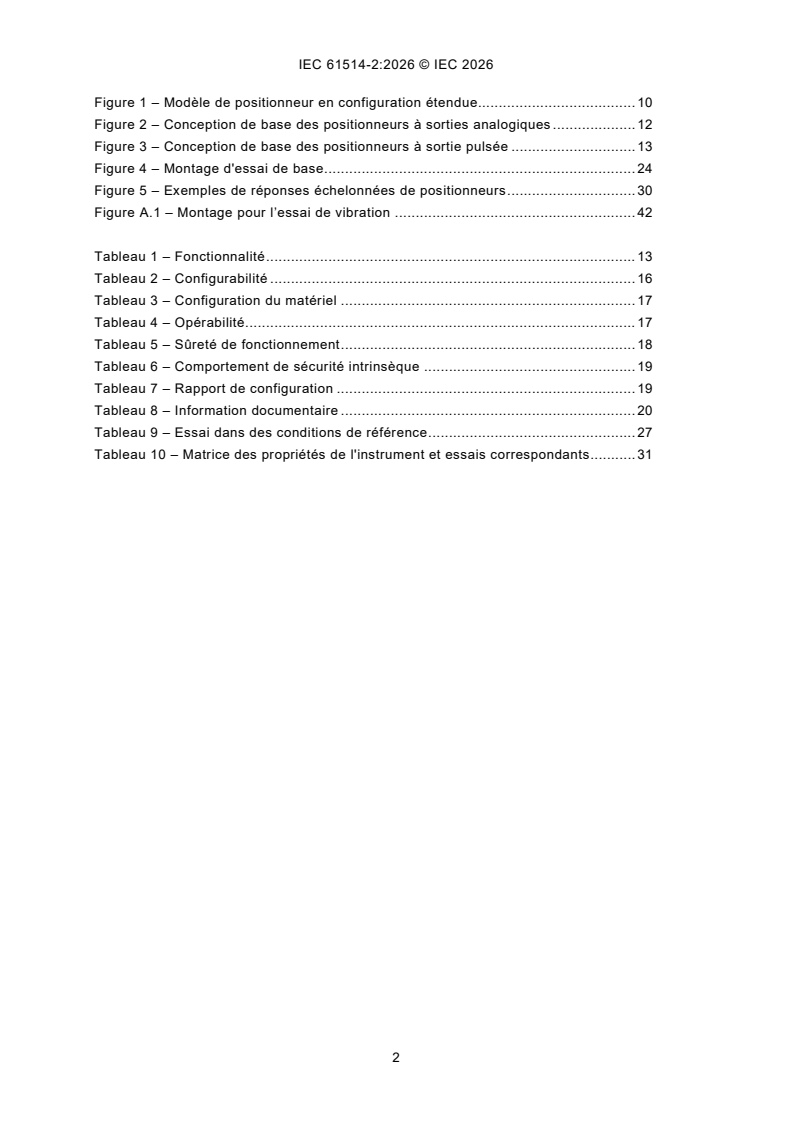
Figure 1 – Positioner model in extensive configuration . 10
Figure 2 – Basic design for positioners with analogue outputs . 12
Figure 3 – Basic design for positioners with pulsed output . 12
Figure 4 – Basic test set-up . 23
Figure 5 – Examples of step responses of positioners . 27
Figure A.1 – Test set-up for vibration test . 39
Table 1 – Functionality . 13
Table 2 – Configurability . 15
Table 3 – Hardware configuration . 16
Table 4 – Operability. 16
Table 5 – Dependability . 17
Table 6 – Fail safe behaviour . 18
Table 7 – Configuration reporting . 18
Table 8 – Document information . 19
Table 9 – Test under reference conditions . 25
Table 10 – Matrix of instrument properties and tests . 28
INTERNATIONAL ELECTROTECHNICAL COMMISSION
____________
Industrial process control systems -
Methods of evaluating the performance of
valve positioners with pneumatic outputs -
Part 2: Test Methods for intelligent positioners
mounted on an actuator valve assembly
FOREWORD
1) The International Electrotechnical Commission (IEC) is a worldwide organization for standardization comprising
all national electrotechnical committees (IEC National Committees). The object of IEC is to promote international
co-operation on all questions concerning standardization in the electrical and electronic fields. To this end and
in addition to other activities, IEC publishes International Standards, Technical Specifications, Technical Reports,
Publicly Available Specifications (PAS) and Guides (hereafter referred to as “IEC Publication(s)”). Their
preparation is entrusted to technical committees; any IEC National Committee interested in the subject dealt with
may participate in this preparatory work. International, governmental and non-governmental organizations liaising
with the IEC also participate in this preparation. IEC collaborates closely with the International Organization for
Standardization (ISO) in accordance with conditions determined by agreement between the two organizations.
2) The formal decisions or agreements of IEC on technical matters express, as nearly as possible, an international
consensus of opinion on the relevant subjects since each technical committee has representation from all
interested IEC National Committees.
3) IEC Publications have the form of recommendations for international use and are accepted by IEC National
Committees in that sense. While all reasonable efforts are made to ensure that the technical content of IEC
Publications is accurate, IEC cannot be held responsible for the way in which they are used or for any
misinterpretation by any end user.
4) In order to promote international uniformity, IEC National Committees undertake to apply IEC Publications
transparently to the maximum extent possible in their national and regional publications. Any divergence between
any IEC Publication and the corresponding national or regional publication shall be clearly indicated in the latter.
5) IEC itself does not provide any attestation of conformity. Independent certification bodies provide conformity
assessment services and, in some areas, access to IEC marks of conformity. IEC is not responsible for any
services carried out by independent certification bodies.
6) All users should ensure that they have the latest edition of this publication.
7) No liability shall attach to IEC or its directors, employees, servants or agents including individual experts and
members of its technical committees and IEC National Committees for any personal injury, property damage or
other damage of any nature whatsoever, whether direct or indirect, or for costs (including legal fees) and
expenses arising out of the publication, use of, or reliance upon, this IEC Publication or any other IEC
Publications.
8) Attention is drawn to the Normative references cited in this publication. Use of the referenced publications is
indispensable for the correct application of this publication.
9) IEC draws attention to the possibility that the implementation of this document may involve the use of (a)
patent(s). IEC takes no position concerning the evidence, validity or applicability of any claimed patent rights in
respect thereof. As of the date of publication of this document, IEC had not received notice of (a) patent(s), which
may be required to implement this document. However, implementers are cautioned that this may not represent
the latest information, which may be obtained from the patent database available at https://patents.iec.ch. IEC
shall not be held responsible for identifying any or all such patent rights.
IEC 61514-2 has been prepared by subcommittee 65B: Measurement and control devices, of
IEC technical committee 65: Industrial-process measurement, control and automation. It is an
International Standard.
This third edition cancels and replaces the second edition published in 2013. This edition
constitutes a technical revision.
This edition includes the following significant technical changes with respect to the previous
edition:
a) in 5.5.2, the standard for the measurements of influence quantities has been changed to
IEC 62828-1:2026;
b) all references to IEC 61514 have been updated to IEC 61514:2026;
c) the aspect of cyber-security has been added in 4.2.7 and 4.2.9.
The text of this International Standard is based on the following documents:
Draft Report on voting
65B/1315/FDIS 65B/1332/RVD
Full information on the voting for its approval can be found in the report on voting indicated in
the above table.
The language used for the development of this International Standard is English.
This document was drafted in accordance with ISO/IEC Directives, Part 2, and developed in
accordance with ISO/IEC Directives, Part 1 and ISO/IEC Directives, IEC Supplement, available
at www.iec.ch/members_experts/refdocs. The main document types developed by IEC are
described in greater detail at www.iec.ch/publications.
This document is to be used in conjunction with IEC 61514:2026.
A list of all parts of the IEC 61514 series, published under the general title Industrial process
control systems, can be found on the IEC website.
The committee has decided that the contents of this document will remain unchanged until the
stability date indicated on the IEC website under webstore.iec.ch in the data related to the
specific document. At this date, the document will be
– reconfirmed,
– withdrawn, or
– revised.
INTRODUCTION
New instruments for process control and measurement including valve positioners are mainly
equipped with microprocessors, thereby utilising digital data processing and communication
methods and/or artificial intelligence, making them more complex and giving them a consider-
able added value.
Modern intelligent valve positioners are no longer only controlling the valve position, but they
are in many cases also equipped with various facilities for self-testing, actuator/valve condition
monitoring and alarming. The variety of added functionalities is large. They can no longer be
compared with the single function "cam-type" positioners. Therefore, accuracy related
performance testing, although still very important, is no longer sufficient to demonstrate their
flexibility, capabilities and other features with respect to engineering, installation, maintain-
ability, reliability and operability.
In this document, the evaluation considers performance testing and a design review of both
hardware and software. The layout of this document follows to some extent the framework of
IEC TS 62098. A number of performance tests described in IEC 61514 are still valid for
intelligent valve positioners.
1 Scope
This part of IEC 61514 specifies design reviews and tests intended to measure and determine
the static and dynamic performance, the degree of intelligence and the communication
capabilities of single-acting or double-acting intelligent valve positioners. The tests can be
applied to positioners which receive standard analogue electrical input signals (as specified in
IEC 60381-1 or IEC 60381-2) and/or digital signals via a data communication link (for example
Fieldbus) and have a pneumatic output. An intelligent valve positioner as defined in Clause 3
is an instrument that uses for performing its functions digital techniques for data processing,
decision-making and bi-directional communication. It can be equipped with additional sensors
and additional functionality supporting the main function.
The performance testing of an intelligent valve positioner is conducted with the positioner
mounted on and connected to the actuator/valve assembly the positioner is used on. The
specific characteristic parameters of the actuator/valve combination such as size, stroke,
friction, type of packing, spring package and supply pressure for the pneumatic part has
significant impact on the performance of a positioner.
The methods of evaluation given in this document are intended for testing laboratories to verify
equipment performance specifications. The manufacturers of intelligent positioners are urged
to apply this document at an early stage of development.
This document is intended to provide guidance for designing evaluations of intelligent valve
positioners by providing:
– a checklist for reviewing their hardware and software design in a structured way;
– test methods for measuring and qualifying their performance under various environmental
and operational conditions;
– methods for reporting the data obtained.
When a full evaluation, in accordance with this document, is not required or possible, the tests
which are required are performed and the results reported in accordance with the relevant
clauses of this document. In such cases, the test report will state that it does not cover the full
number of tests specified herein. Furthermore, the items omitted are mentioned, to give the
reader of the report a clear overview.
This document is also applicable for non-intelligent microprocessor-based valve positioners
without means for bi-directional communication. In that case an evaluation will be reduced to a
limited programme of performance testing and a review of the construction.
2 Normative references
The following documents, in whole or in part, are normatively referenced in this document and
are indispensable for its application. For dated references, only the edition cited applies. For
undated references, the latest edition of the referenced document (including any amendments)
applies.
IEC 60050-300, International electrotechnical vocabulary (IEV) - International Electrotechnical
Vocabulary Electrical and electronic measurements and measuring instruments - Part 311:
General terms relating to measurements - Part 312: General terms relating to electrical
measurements - Part 313: Types of electrical measuring instruments - Part 314: Specific terms
according to the type of instrument
IEC 60050-351, International electrotechnical vocabulary (IEV) - Part 351: Control technology
IEC 60068-2-1, Environmental testing - Part 2-1: Tests - Tests A: Cold
IEC 60068-2-2, Environmental testing - Part 2-2: Tests - Test B: Dry heat
IEC 60068-2-6, Environmental testing - Part 2-6: Tests - Test Fc: Vibration (sinusoidal)
IEC 60068-2-31, Environmental testing - Part 2-31: Tests - Test Ec: Rough handling shocks,
primarily for equipment-type specimens
IEC 60068-2-78, Environmental testing - Part 2-78: Tests - Test Cab: Damp heat, steady state
IEC 60079 (all parts), Explosive atmospheres
IEC 60381-1, Analogue signals for process control systems - Part 1: Direct current signals
IEC 60381-2, Analogue signals for process control systems - Part 2: Direct voltage signals
IEC 60529, Degrees of protection provided by enclosures (IP Code)
IEC 60534-1, Industrial-process control valves - Part 1: Control valve terminology and general
considerations
IEC 60654 (all parts), Operating conditions for industrial-process measurement and control
equipment
IEC 60721-3 (all parts), Classification of environmental conditions - Part 3 Classification of
groups of environmental parameters and their severities
IEC 61010-1, Safety requirements for electrical equipment for measurement, control, and
laboratory use - Part 1: General requirements
IEC 61032, Protection of persons and equipment by enclosures - Probes for verification
IEC 61326-1:2020, Electrical equipment for measurement, control and laboratory use - EMC
requirements - Part 1: General requirements
IEC 61508 (all parts), Functional safety of electrical/electronic/programmable electronic safety-
related systems
IEC 61511 (all parts), Functional safety - Safety instrumented systems for the process industry
sector
IEC 61514:2026, Industrial-process control systems - Methods of evaluating the performance
of valve positioners with pneumatic outputs
IEC 62061, Safety of machinery - Functional safety of safety-related control systems
IEC 62828-1:2026, Reference conditions and procedures for testing industrial and process
measurement transmitters - Part 1: General procedures for all types of transmitters
3 Terms and definitions
For the purposes of this document, the terms and definitions given in IEC 60050-311,
IEC 60050-351 and IEC 61514 as well as the following apply.
ISO and IEC maintain terminology databases for use in standardization at the following
addresses:
– IEC Electropedia: available at https://www.electropedia.org/
– ISO Online browsing platform: available at https://www.iso.org/obp
3.1
intelligent valve positioner
position controller based on microprocessor technology, and utilising digital techniques for data
processing, decision-making and bi-directional communication
Note 1 to entry: It may be equipped with additional sensors and additional functionality supporting the main function.
Note 2 to entry: In this document, only positioners with pneumatic output signals are considered, as defined in 3.1
of IEC 61514:2026. The input signal may be an electric current or voltage, or a digital signal via a fieldbus.
Note 3 to entry: For non-intelligent microprocessor-based position controllers without bi-directional communication,
an evaluation is reduced to a limited amount of performance testing and an abridged design review of the
construction.
3.2
configuring
process of implementing the functionality required for a certain application
3.3
configurability
extent to which an intelligent positioner can be provided with functions to control various
applications
3.4
calibration
process of adjusting the range of travel to the required value for acquiring a defined input-to-
travel characteristic
Note 1 to entry: The adjusted travel can either be from stop to stop or to a value in between as defined by the valve
manufacturer.
Note 2 to entry: Instruments may exist that are provided with an automatic procedure for travel range adjustment,
which may then be addressed with the term auto-calibration.
Note 3 to entry: The calibration process describes the adjustment of a positioner to a given actuator/valve assembly
and is not comparable with the definition given in IEC 60050-311:2001, 311-01-09.
3.5
tuning
process of adjusting the various control parameters for a certain application
Note 1 to entry: The stem position tuning procedure can range from "trial and error" to an automatic proprietary
procedure provided by the manufacturer and often addressed as auto-tuning.
3.6
set-up
process of configuring, calibrating and tuning a positioner for optimal controlling of a specific
actuator/valve assembly
3.7
travel cut-off
point close to the extreme end (low or high) of the characteristic curve at which the positioner
forces the valve to the corresponding mechanical stop (fully closed or fully open)
3.8
stroke time
time required to travel between two different positions under a defined set of conditions
3.9
dead band
finite range of values of the input variable within which a variation of the input variable does not
produce any measurable change in the output variable
[SOURCE: IEC 60050-351:2013, 351-45-15, modified – Notes 1 and 2 to entry have been
removed.]
3.10
operating mode
selected method of operation of the positioner
Note 1 to entry: The above definition is different from the definition given in IEC 60050-351:2013, 351-55-01.
3.11
setpoint
input variable, which sets the desired value of the controlled variable (travel)
Note 1 to entry: The input variable can originate from an analogue source (mA or voltage) or from a digital source
(fieldbus) or local keyboard.
3.12
balance pressure
average of the pressures on the opposite chambers of a double acting actuator in steady state
condition
Note 1 to entry: The balance pressure shall be expressed as a percentage of the positioner supply pressure to
evaluate the stiffness of the double acting system.
4 Design review
4.1 General
The observations of Clause 4 shall be based on open literature (manuals, instruction leaflets,
etc.) provided to a user on delivery of the instruments and whatever the manufacturer is willing
to disclose. They shall not contain confidential information.
The design review is meant to identify and make explicit the functionality and capabilities of the
intelligent valve positioner under consideration in a structured way. As intelligent positioners
appear in a great variety of designs a review has to show in a structured way the details of
– their physical structure;
– their functional structure.
Subclause 4.2 guides the evaluator in the process of describing the physical structure of
intelligent positioners through identifying the hardware modules and the I/Os to the operational
and environmental domains.
Thereafter the functional structure is described using the checklist of 4.3. The checklist gives a
structured framework of the relevant issues, which have to be addressed by the evaluator
through adequate qualitative and quantitative experiments.
4.2 Positioner identification
4.2.1 Overview
The structured identification process, based on the following considerations, leads to a block
scheme and a concise description of the positioner under test, which shall be included in the
evaluation report. It may be enhanced with photographs or drawings of important details.
The instrument, schematically shown in Figure 1, can have the following main physical modules
and provisions for connection to the external world:
Figure 1 – Positioner model in extensive configuration
4.2.2 Power supply unit
Instruments that require a separate connection to an AC or DC supply voltage can exist.
However, the majority of instruments are "loop powered" which means that they receive power
either through the current input for instruments that need an analogue signal (mA) setpoint, or
through the fieldbus when the setpoint is a digital signal.
4.2.3 Sensor/input assembly
The main sensor/input assembly is that part of the positioner to which the analogue setpoint is
connected and which also receives the feedback signal from the actuator/valve assembly (stem
movement). It supports the primary function of the positioner. Parts of the assembly can be
distributed at physically different locations in the positioner. In instruments that receive a digital
setpoint, the input signal W as shown in Figure 4 does not exist. The feedback signal can be
generated by a mechanical linkage or a non-mechanical interface between the positioner and
the valve stem.
4.2.4 Auxiliary sensor assembly
The auxiliary sensor assembly is for the electronics part integrated with the main sensor input
assembly. Many positioners are equipped with a pressure sensor in the pneumatic supply and
output circuit and a temperature sensor inside the electronics housing. Their signals can be
used in the stem position control algorithm. For safeguarding and condition monitoring of the
valve, a positioner can be equipped with additional sensors. It can also be equipped with circuits
for digital inputs from switches.
4.2.5 Human interface
A positioner can be classified as intelligent only when data produced by the positioner can be
communicated to the external world. The human interface is an important tool for
communication. It consists of integral means at the instrument for reading out data (local
display) and provisions for entering and requesting data (local pushbuttons). It can appear that
some instruments are not equipped with a human interface. In these cases, access is provided
via the data communication interface and an external device (handheld terminal or PC).
4.2.6 Communication interface
Positioner intelligence is further supported by the communication interface, which connects the
positioner to external systems. Through the interface and a fieldbus, data transfer (setpoint,
configuration and process data) takes place between the positioner and the external system.
There are also hybrid instruments, which require an analogue input for control data where the
data communication interface is integrated in the input circuit and has no separate point of
connection for the fieldbus. The digital information is superimposed on the analogue input
current. There are instruments which do not have a communication interface. Then
configuration and read-out of data take place via the local human interface.
4.2.7 Data processing unit
The data processing unit provides the instrument with a number of functions that can vary
considerably from make to make. The functions that can be implemented include:
– control function;
– configuration;
– calibration;
– tuning;
– valve condition monitoring (valve diagnostics);
– external process control function;
– self-testing;
– trending and data storage;
– cyber-security.
Part of the functionality can be located in external devices that are temporarily or continuously
connected to the data communication interface (e.g. configuration, trending).
4.2.8 Output subsystem
In the single acting version, the output subsystem converts the digital information via an electro-
pneumatic converter (E/P) into the pneumatic signal for controlling the actuator.
In the double acting version, the output subsystem is equipped with two oppositely operating
E/P converters. In balanced (steady) position, the converters provide pressures that, apart from
the friction force to the valve stem, are equal. The relation between the balance pressure and
the supply pressure determines the stiffness of a double acting system.
With respect to the pneumatic unit, the following two designs are, among others, commonly
used:
– analogue techniques of conventional E/P converters as shown in Figure 2;
– electronically controlled two-state pilot valves as shown in Figure 3.
Moreover, the output subsystem can also be provided with isolated analogue signal outputs
proportional to one (or more) of the measured or calculated data and/or one or more
configurable output relays for alarm purposes. Such outputs usually require a separate power
supply.
Figure 2 – Basic design for positioners with analogue outputs
Figure 3 – Basic design for positioners with pulsed output
4.2.9 External functionality
Through the data communication interface, the instrument communicates with PCs, handheld
devices and DCS systems. In many cases, a part of the functionality of the positioner can reside
in these external devices. This can include the following functions:
– (remote) configuration tool;
– data storage (configuration, position trend, valve condition);
– parts of the calibration and stem tuning procedure;
– automated valve condition monitoring and alarming;
– cyber-security.
In an evaluation, the external functionality (if present) shall be considered as well.
4.3 Aspects of functionality and capabilities to be reviewed
The following Table 1, Table 2, Table 3, Table 4, Table 5, Table 6 and Table 7 shall serve as a
checklist for the determination of the functions and capabilities implemented in the positioner
under consideration.
Table 1 – Functionality
Function/capability Aspects to be considered during evaluation
Suitable for rotary valve If so, also indicate the stroke range and describe the accessories required for
mechanical linkage.
Suitable for linear stroke valve If so, also indicate the stroke range and describe the accessories required for
mechanical linkage.
Direct/reverse action Check whether choice of direct/reverse action is possible and describe how
the mechanism operates.
Double acting version Check one of the following:
– always included
– can be retrofitted
– available with different order number
– not available
Stem position control algorithm For each control parameter give:
parameters
– name
– adjustment range if user-adjustable
– default values if applicable
check whether invalid values are recognised and rejected
check whether negative values are accepted, if so observe behaviour on
instability after step change
check if outputs of internal sensors are used in the stem position control
algorithm and check whether and how backup is provided in case of sensor
failure
some designs have a double set of control parameters for upscale or
downscale movement, verify
what value defines indefinite (‘99999’ or ‘0’)?
Other parameters affecting For a number of parameters (supply pressure, valve and actuator data, etc.),
control values can be requested to be entered during configuration. They can be used
in the stem position control algorithm. Check whether they are indeed used in
the stem position control algorithm or are informative only.
Operating modes List the available operating modes, their hierarchy, span of control, switching
order (also check availability of bumpless transfer), degree of authorised
access to positioner database (configuration, control parameters, secondary
parameters).
Operating modes could be:
– out of service or standby
– automatic control
– manual control (local or remote)
Split range application Is split range operation possible?
If so, state the adjustable value range.
Stroke time Check whether the stroke time is user-adjustable. State the adjustable value
range.
Travel cut-off Cut-off is usually possible at the lower end of the characteristic (also known
as tight shut-off), but also cut-off at the upper end can be present. Indicate
which option is available and whether cut-off values are user-configurable.
Check whether a dead band is implemented and operational between
activation and release. Indicate whether it is related to the input signal or to
the feedback position signal.
Function/capability Aspects to be considered during evaluation
Filters If filters are provided, what type of filters?
External (process) control Can function blocks (according to IEC 61499 series) for an external control
loop be implemented?
Special functions Indicate if special functions are available (e.g. pressure sensor in actuator,
leak detection, flow measurement, hardware limit switches).
Valve diagnostics Check whether implemented valve diagnostics cover the following aspects:
– change in performance of control valve (dead band, resolution, etc.)
– change of friction
– wear of plug
– wear of stem
– packing leakage
– seat leakage
– break of stem
– cavitation
– broken actuator spring
– air leakage at actuator
– valve stuck
– torn diaphragm at actuator
– detection of reduction of performance by plugging of pneumatic
Other aspects
Checks on extent of and tools for Check how the valve diagnostics aspects mentioned above are diagnosed,
valve diagnostics tested, stored, reported and presented by the positioner or the host system.
Does the diagnostic tool provide direct automatic interpretation by the
instrument or does it require a specific level of human expertise. For each
aspect check which of the tools (tests) mentioned below are used, check per
tool the following points:
– whether the diagnostic tests can be performed in-service
– whether it is an on-line automatic test or an operator-initiated
– check intervals between automatic tests
– check user-adaptability of test parameters
– check whether test affects the stem position
– indicate whether data can be stored and where (local or remote (e.g. in
PC))
– check whether there is a related direct alert/alarm message or whether it
has to be deduced by the user from other information given by the
positioner. (Example: Many positioners are equipped with a user-
adjustable alarm indicating that the valve is not reaching its position in a
certain time. Break of stem, and broken spring will most probably trigger
this alarm)
– check the action of the positioner on appearance of diagnostic alarms
Tools (tests) that can be present are amongst other things:
– high/low position alarms
– rate of change alarm
– cycle counter/accumulator
– travel accumulator
– valve signature test
– step response test
– time to settle exceeds the set limit
– accumulator for time close to zero
Table 2 – Configurability
Function/capability Aspects to be considered during evaluation
Fieldbus compatibility Check whether the instrument under test is suited for either:
® a
– HART
® b
– PROFIBUS PA
® b
– PROFIBUS DP
™ a
FIELDBUS H1
– FOUNDATION
™ a
– FOUNDATION FIELDBUS HSE
– Other (state details)
Configuration tools Check if the instrument can be configured:
– from local controls (human interface) on instrument
– remotely from PC or a host computer
– via handheld communication unit to be connected temporarily
– other
On-line (re)configuration Check whether parameters can be changed in control mode, if so whether the
position of the valve stem is unacceptably affected.
Check whether there is a security mechanism that prohibits on-line access to
all or some parameters.
Off-line configuration Check whether it is possible to set up and store configurations for a number of
positioners on a separate (off-line) PC, which is not connected to a positioner.
Up/download to/from PC Check if configuration upload is possible. Check if download of off-line
prepared configurations is possible.
Configurable travel Mention user-selectable characteristics that reside in the instrument, such as:
characteristics
– linear
– equal percentage as defined in IEC 60534-1 (1:50; 1:30; 1:25, etc.)
– quick opening
– segmental (user defined travel characteristic), mention number of
segments
The equal percentage characteristic is sometimes realised by segmental
approach. It is important to state the number of segments and their size and to
evaluate the maximum errors with respect to the theoretical equal percentage
characteristic.
Configurable “fail-safe” position Check the availability of a configurable fail-safe position. Note the behaviour
for the different failure modes. Use Table 6 to check behaviour.
Balance pressure Check whether the balance pressure for the double acting version is
user-adjustable.
Conditions on start-up after loss After a power down there can be the requirement the positioner to return to a
of power or an instrument reset defined position. Positioners may be provided with:
– return to last value
– go to fail-safe
– go to a user-defined value
– return to control in manual mode
a ®
HART , FOUNDATION™ FIELDBUS H1 and FOUNDATION™ FIELDBUS HSE are the trade names of products
supplied by FieldComm Group™. This information is given for the convenience of users of this document and
does not constitute an endorsement by IEC of the products named. Equivalent products may be used if they
can be shown to lead to the same results.
b
PROFIBUS PA and PROFIBUS DP are the trade names of products supplied by the non-profit organization
PROFIBUS Nutzerorganisation e.V. (PNO). This information is given for the convenience of users of this
document and does not constitute an endorsement by IEC of the products named. Equivalent products may be
used if they can be shown to lead to the same results.
Table 3 – Hardware configuration
Function/capability Aspects to be considered during evaluation
Hinged covers – Complexity and soundness of construction and protection against
damage
Valve position feedback mechanism
– Separate termination compartment
Internal modules
– Availability of material of construction for severe service
Support to valve
application (e.g. offshore, food)
Protruding parts
– Availability of integrated pneumatic connections
Local controls – Availability of quick connect provisions for electrical and
pneumatic connections
Electrical connections
– Isolation of pneumatic and electronic compartments
Pneumatic connections
Remote position sensor Check the availability of a remote position sensor that provides
mechanical separation of the electronics and comment on soundness
and ease of installation and calibration.
Table 4 – Operability
Function/capability Aspects to be considered during evaluation
Local controls (tools) for access Give a concise description of:
– available controls (pushbuttons, etc.)
– accessibility
– ergonomic layout and use of the controls
– can controls be used in hazardous locations?
Local displays Give a concise description of data that can be shown on the local displays:
– number of lines and characters per line
– control parameters given
– error messages, etc.
Is display readable without removing covers?
Human interface at external Give a concise description of the organisation and hierarchy of the various
system user access groups and related displays in the PC based software.
Give for a handheld communicator a picture with layout of display and
keyboard.
Other points for human List other hardware tools (switches, potentiometers, etc.) and the related
interaction parameters they control.
Robustness
Table 5 – Dependability
Function/capability Aspects to be considered during evaluation
Positioner diagnostics Describe in short the extent of the system for diagnosing internal positioner
failures and securing safe operation in case of failures. Mechanisms can be
implemented for detecting:
– memory failure
– no free CPU time
– reference voltage failure
– input current out of range
...
IEC 61514-2 ®
Edition 3.0 2026-08
INTERNATIONAL
STANDARD
REDLINE VERSION
Industrial process control systems -
Part 2: Methods of evaluating the performance of intelligent valve positioners
with pneumatic outputs -
Part 2: Test Methods for intelligent positioners mounted on an actuator valve
assembly
ICS 23.060.99; 25.040.40 ISBN 978-2-8327-1441-6
All rights reserved. Unless otherwise specified, no part of this publication may be reproduced or utilized in any form or
by any means, electronic or mechanical, including photocopying and microfilm, without permission in writing from either
IEC or IEC's member National Committee in the country of the requester. If you have any questions about IEC copyright
or have an enquiry about obtaining additional rights to this publication, please contact the address below or your local
IEC member National Committee for further information.
IEC Secretariat Tel.: +41 22 919 02 11
3, rue de Varembé info@iec.ch
CH-1211 Geneva 20 www.iec.ch
Switzerland
About the IEC
The International Electrotechnical Commission (IEC) is the leading global organization that prepares and publishes
International Standards for all electrical, electronic and related technologies.
About IEC publications
The technical content of IEC publications is kept under constant review by the IEC. Please make sure that you have the
latest edition, a corrigendum or an amendment might have been published.
IEC publications search - IEC Products & Services Portal - products.iec.ch
webstore.iec.ch/advsearchform Discover our powerful search engine and read freely all the
The advanced search enables to find IEC publications by a publications previews, graphical symbols and the glossary.
variety of criteria (reference number, text, technical With a subscription you will always have access to up to date
committee, …). It also gives information on projects, content tailored to your needs.
replaced and withdrawn publications.
Electropedia - www.electropedia.org
IEC Just Published - webstore.iec.ch/justpublished The world's leading online dictionary on electrotechnology,
Stay up to date on all new IEC publications. Just Published containing more than 22 500 terminological entries in English
details all new publications released. Available online and and French, with equivalent terms in 25 additional languages.
once a month by email. Also known as the International Electrotechnical Vocabulary
(IEV) online.
IEC Customer Service Centre - webstore.iec.ch/csc
If you wish to give us your feedback on this publication or
need further assistance, please contact the Customer
Service Centre: sales@iec.ch.
CONTENTS
FOREWORD . 3
INTRODUCTION . 5
1 Scope . 6
2 Normative references . 6
3 Terms and definitions . 8
4 Design review . 10
4.1 General . 10
4.2 Positioner identification . 10
4.2.1 Overview . 10
4.2.2 Power supply unit . 11
4.2.3 Sensor/input assembly . 11
4.2.4 Auxiliary sensor assembly . 11
4.2.5 Human interface . 11
4.2.6 Communication interface . 12
4.2.7 Data processing unit . 12
4.2.8 Output subsystem . 12
4.2.9 External functionality . 13
4.3 Aspects of functionality and capabilities to be reviewed . 13
4.3.1 Checklist .
4.3.2 Reporting .
4.4 Documentary information . 20
5 Performance testing . 21
5.1 General . 21
5.2 Standard reference test conditions for performance tests . 21
5.2.1 Overview . 21
5.2.2 Valve characteristics. 22
5.3 General testing procedures . 23
5.3.1 Test set-up . 23
5.3.2 Testing precautions . 24
5.4 Initial observations and measurements . 24
5.4.1 Overview . 24
5.4.2 Mounting procedure . 24
5.4.3 Configuration procedures. 25
5.4.4 Stem position calibration procedure . 25
5.4.5 Stem position tuning procedure . 25
5.5 Performance test procedures . 25
5.5.1 General . 25
5.5.2 Effects of influence quantities . 30
6 Other considerations . 32
6.1 Safety . 40
6.2 Degree of protection provided by enclosures . 40
6.3 Electromagnetic emission . 40
6.4 Variants . 40
6.5 Installation . 40
7 Evaluation report . 40
Annex A (normative) Vibration test set-up . 42
Bibliography . 43
Figure 1 – Positioner model in extensive configuration . 11
Figure 2 – Basic design for positioners with analogue outputs . 13
Figure 3 – Basic design for positioners with pulsed output . 13
Figure 4 – Basic test set-up . 24
Figure 5 – Examples of step responses of positioners . 30
Figure A.1 – Test set-up for vibration test . 42
Table 1 – Functionality . 14
Table 2 – Configurability . 16
Table 3 – Hardware configuration . 17
Table 4 – Operability. 17
Table 5 – Dependability . 18
Table 6 – Fail safe behaviour . 19
Table 7 – Configuration reporting . 19
Table 8 – Document information . 20
Table 9 – Test under reference conditions . 26
Table 10 – Matrix of instrument properties and tests . 32
INTERNATIONAL ELECTROTECHNICAL COMMISSION
____________
Industrial process control systems -
Part 2: Methods of evaluating the performance of intelligent
valve positioners with pneumatic outputs -
Part 2: Test Methods for intelligent positioners
mounted on an actuator valve assembly
FOREWORD
1) The International Electrotechnical Commission (IEC) is a worldwide organization for standardization comprising
all national electrotechnical committees (IEC National Committees). The object of IEC is to promote international
co-operation on all questions concerning standardization in the electrical and electronic fields. To this end and
in addition to other activities, IEC publishes International Standards, Technical Specifications, Technical Reports,
Publicly Available Specifications (PAS) and Guides (hereafter referred to as “IEC Publication(s)”). Their
preparation is entrusted to technical committees; any IEC National Committee interested in the subject dealt with
may participate in this preparatory work. International, governmental and non-governmental organizations liaising
with the IEC also participate in this preparation. IEC collaborates closely with the International Organization for
Standardization (ISO) in accordance with conditions determined by agreement between the two organizations.
2) The formal decisions or agreements of IEC on technical matters express, as nearly as possible, an international
consensus of opinion on the relevant subjects since each technical committee has representation from all
interested IEC National Committees.
3) IEC Publications have the form of recommendations for international use and are accepted by IEC National
Committees in that sense. While all reasonable efforts are made to ensure that the technical content of IEC
Publications is accurate, IEC cannot be held responsible for the way in which they are used or for any
misinterpretation by any end user.
4) In order to promote international uniformity, IEC National Committees undertake to apply IEC Publications
transparently to the maximum extent possible in their national and regional publications. Any divergence between
any IEC Publication and the corresponding national or regional publication shall be clearly indicated in the latter.
5) IEC itself does not provide any attestation of conformity. Independent certification bodies provide conformity
assessment services and, in some areas, access to IEC marks of conformity. IEC is not responsible for any
services carried out by independent certification bodies.
6) All users should ensure that they have the latest edition of this publication.
7) No liability shall attach to IEC or its directors, employees, servants or agents including individual experts and
members of its technical committees and IEC National Committees for any personal injury, property damage or
other damage of any nature whatsoever, whether direct or indirect, or for costs (including legal fees) and
expenses arising out of the publication, use of, or reliance upon, this IEC Publication or any other IEC
Publications.
8) Attention is drawn to the Normative references cited in this publication. Use of the referenced publications is
indispensable for the correct application of this publication.
9) IEC draws attention to the possibility that the implementation of this document may involve the use of (a)
patent(s). IEC takes no position concerning the evidence, validity or applicability of any claimed patent rights in
respect thereof. As of the date of publication of this document, IEC had not received notice of (a) patent(s), which
may be required to implement this document. However, implementers are cautioned that this may not represent
the latest information, which may be obtained from the patent database available at https://patents.iec.ch. IEC
shall not be held responsible for identifying any or all such patent rights.
This redline version of the official IEC Standard allows the user to identify the changes made
to the previous edition IEC 61514-2:2013. A vertical bar appears in the margin wherever a
change has been made. Additions are in green text, deletions are in strikethrough red text.
IEC 61514-2 has been prepared by subcommittee 65B: Measurement and control devices, of
IEC technical committee 65: Industrial-process measurement, control and automation. It is an
International Standard.
This third edition cancels and replaces the second edition published in 2013. This edition
constitutes a technical revision.
This edition includes the following significant technical changes with respect to the previous
edition:
a) in 5.5.2, the standard for the measurements of influence quantities has been changed to
IEC 62828-1:2026;
b) all references to IEC 61514 have been updated to IEC 61514:2026;
c) the aspect of cyber-security has been added in 4.2.7 and 4.2.9.
The text of this International Standard is based on the following documents:
Draft Report on voting
65B/1315/FDIS 65B/1332/RVD
Full information on the voting for its approval can be found in the report on voting indicated in
the above table.
The language used for the development of this International Standard is English.
This document was drafted in accordance with ISO/IEC Directives, Part 2, and developed in
accordance with ISO/IEC Directives, Part 1 and ISO/IEC Directives, IEC Supplement, available
at www.iec.ch/members_experts/refdocs. The main document types developed by IEC are
described in greater detail at www.iec.ch/publications.
This document is to be used in conjunction with IEC 61514:2026.
A list of all parts of the IEC 61514 series, published under the general title Industrial process
control systems, can be found on the IEC website.
The committee has decided that the contents of this document will remain unchanged until the
stability date indicated on the IEC website under webstore.iec.ch in the data related to the
specific document. At this date, the document will be
– reconfirmed,
– withdrawn, or
– revised.
INTRODUCTION
New instruments for process control and measurement including valve positioners are mainly
equipped with microprocessors, thereby utilising digital data processing and communication
methods and/or artificial intelligence, making them more complex and giving them a consider-
able added value.
Modern intelligent valve positioners are no longer only controlling the valve position, but they
are in many cases also equipped with various facilities for self-testing, actuator/valve condition
monitoring and alarming. The variety of added functionalities is large. They can no longer be
compared with the single function "cam-type" positioners. Therefore, accuracy related
performance testing, although still very important, is no longer sufficient to demonstrate their
flexibility, capabilities and other features with respect to engineering, installation, maintain-
ability, reliability and operability.
In this document, the evaluation considers performance testing and a design review of both
hardware and software. The layout of this document follows to some extent the framework of
IEC TS 62098. A number of performance tests described in IEC 61514 are still valid for
intelligent valve positioners. Further reading of IEC 61069 is recommended.
1 Scope
This part of IEC 61514 specifies design reviews and tests intended to measure and determine
the static and dynamic performance, the degree of intelligence and the communication
capabilities of single-acting or double-acting intelligent valve positioners. The tests may can be
applied to positioners which receive standard analogue electrical input signals (as specified in
IEC 60381-1 or IEC 60381-2) and/or digital signals via a data communication link (for example
Fieldbus) and have a pneumatic output. An intelligent valve positioner as defined in Clause 3
is an instrument that uses for performing its functions digital techniques for data processing,
decision-making and bi-directional communication. It may can be equipped with additional
sensors and additional functionality supporting the main function.
The performance testing of an intelligent valve positioner needs to be is conducted with the
positioner mounted on and connected to the actuator/valve assembly the positioner is used on.
The specific characteristic parameters of these combinations the actuator/valve combination
such as size, stroke, friction (hysteresis), type of packing, spring package and supply pressure
for the pneumatic part, should be carefully chosen and reported, since the has significant impact
on the performance of a positioner is greatly dependent on the used actuator.
The methods of evaluation given in this document are intended for testing laboratories to verify
equipment performance specifications. The manufacturers of intelligent positioners are urged
to apply this document at an early stage of development.
This document is intended to provide guidance for designing evaluations of intelligent valve
positioners by providing:
– a checklist for reviewing their hardware and software design in a structured way;
– test methods for measuring and qualifying their performance under various environmental
and operational conditions;
– methods for reporting the data obtained.
When a full evaluation, in accordance with this document, is not required or possible, the tests
which are required should be are performed and the results should be reported in accordance
with the relevant clauses of this document. In such cases, the test report should will state that
it does not cover the full number of tests specified herein. Furthermore, the items omitted should
be are mentioned, to give the reader of the report a clear overview.
This document is also applicable for non-intelligent microprocessor-based valve positioners
without means for bi-directional communication. In that case an evaluation should will be
reduced to a limited programme of performance testing and a review of the construction.
2 Normative references
The following documents, in whole or in part, are normatively referenced in this document and
are indispensable for its application. For dated references, only the edition cited applies. For
undated references, the latest edition of the referenced document (including any amendments)
applies.
IEC 60050 (all parts), International Electrotechnical Vocabulary (IEV) (available at
http://www.electropedia.org)
IEC 60050-300, International electrotechnical vocabulary (IEV) - International Electrotechnical
Vocabulary Electrical and electronic measurements and measuring instruments - Part 311:
General terms relating to measurements - Part 312: General terms relating to electrical
measurements - Part 313: Types of electrical measuring instruments - Part 314: Specific terms
according to the type of instrument
IEC 60050-351, International electrotechnical vocabulary (IEV) - Part 351: Control technology
IEC 60068-2-1:1990, Environmental testing - Part 2-1: Tests - Tests A: Cold
IEC 60068-2-2:1974, Environmental testing - Part 2-2: Tests - Test B: Dry heat
IEC 60068-2-6:1995, Environmental testing - Part 2-6: Tests - Test Fc: Vibration (sinusoidal)
IEC 60068-2-31:1969, Environmental testing - Part 2-31: Tests - Test Ec: Drop and topple
Rough handling shocks, primarily for equipment-type specimens
IEC 60068-2-78:2001, Environmental testing - Part 2-78: Tests - Test Cab: Damp heat, steady
state
IEC 60079 (all parts), Electrical apparatus for explosive gas Explosive atmospheres
IEC 60381-1, Analogue signals for process control systems - Part 1: Direct current signals
IEC 60381-2, Analogue signals for process control systems - Part 2: Direct voltage signals
IEC 60529:1989, Degrees of protection provided by enclosures (IP Code)
IEC 60534-1, Industrial-process control valves - Part 1: Control valve terminology and general
considerations
IEC 60654 (all parts), Operating conditions for industrial-process measurement and control
equipment
IEC 60721-3 (all parts), Classification of environmental conditions - Part 3 Classification of
groups of environmental parameters and their severities
IEC 61000-4-11, Electromagnetic compatibility (EMC) – Part 4-11: Testing and measurement
techniques – Voltage dips, short interruptions and voltage variations immunity tests
IEC 61010-1:2001, Safety requirements for electrical equipment for measurement, control, and
laboratory use - Part 1: General requirements
IEC 61032:1997, Protection of persons and equipment by enclosures - Probes for verification
IEC 61069 (all parts), Industrial-process measurement and control – Evaluation of system
properties for the purpose of system assessment
IEC 61158 (all parts), Digital data communications for measurement and control – Fieldbus for
use in industrial control systems
IEC 61298 (all parts), Process measurement and control devices – General methods and
procedures for evaluating performance
IEC 61298-1:2008, Process measurement and control devices – General methods and
procedures for evaluating performance – Part 1: General considerations
IEC 61298-2:2008, Process measurement and control devices – General methods and
procedures for evaluating performance – Part 2: Tests under reference conditions
IEC 61298-3:2008, Process measurement and control devices – General methods and
procedures for evaluating performance – Part 3: Tests for the effects of influence quantities
IEC 61298-4:2008, Process measurement and control devices – General methods and
procedures for evaluating performance – Part 4: Evaluation report content
IEC 61326-1:20052020, Electrical equipment for measurement, control and laboratory use -
EMC requirements - Part 1: General requirements
IEC/PAS 61499 (all parts), Function blocks for industrial-process measurement and control
systems
IEC 61508 (all parts), Functional safety of electrical/electronic/programmable electronic safety-
related systems
IEC 61511 (all parts), Functional safety - Safety instrumented systems for the process industry
sector
IEC 61514:20002026, Industrial-process control systems –- Methods of evaluating the
performance of valve positioners with pneumatic outputs
IEC 62061, Safety of machinery - Functional safety of safety-related control systems
IEC/TS 62098, Evaluation methods for microprocessor-based instruments
IEC 62828-1:2026, Reference conditions and procedures for testing industrial and process
measurement transmitters - Part 1: General procedures for all types of transmitters
CISPR 11, Information technology equipment – Radio disturbance characteristics – Limits and
methods of measurement
3 Terms and definitions
For the purposes of this document, the terms and definitions given in IEC 60050-311,
IEC 60050-351 and IEC 61514 as well as the following apply.
ISO and IEC maintain terminology databases for use in standardization at the following
addresses:
– IEC Electropedia: available at https://www.electropedia.org/
– ISO Online browsing platform: available at https://www.iso.org/obp
3.1
intelligent valve positioner
position controller based on microprocessor technology, and utilising digital techniques for data
processing, decision-making and bi-directional communication
Note 1 to entry: It may be equipped with additional sensors and additional functionality supporting the main function.
Note 2 to entry: In this document, only positioners with pneumatic output signals are considered, as defined in 3.1
of IEC 61514:20002026. The input signal may be an electric current or voltage, or a digital signal via a fieldbus.
Note 3 to entry: For non-intelligent microprocessor-based position controllers without bi-directional communication,
an evaluation is reduced to a limited amount of performance testing and an abridged design review of the
construction.
3.2
configuring
process of implementing the functionality required for a certain application
3.3
configurability
extent to which an intelligent positioner can be provided with functions to control various
applications
3.4
calibration
process of adjusting the range of travel to the required value for acquiring a defined input-to-
travel characteristic
Note 1 to entry: The adjusted travel can either be from stop to stop or to a value in between as defined by the valve
manufacturer.
Note 2 to entry: Instruments may exist that are provided with an automatic procedure for travel range adjustment,
which may then be addressed with the term auto-calibration.
Note 3 to entry: The calibration process describes the adjustment of a positioner to a given actuator/valve assembly
and is not comparable with the definition given in IEC 60050-311:2001, 311-01-09.
3.5
tuning
process of adjusting the various control parameters for a certain application
Note 1 to entry: The stem position tuning procedure can range from "trial and error" to an automatic proprietary
procedure provided by the manufacturer and often addressed as auto-tuning.
3.6
set-up
process of configuring, calibrating and tuning a positioner for optimal controlling of a specific
actuator/valve assembly
3.7
travel cut-off
point close to the extreme end (low or high) of the characteristic curve at which the positioner
forces the valve to the corresponding mechanical stop (fully closed or fully open)
3.8
stroke time
time required to travel between two different positions under a defined set of conditions
3.9
dead band
finite range of values of the input variable within which reversal a variation of the input variable
does not produce any noticeable measurable change in the output variable
[SOURCE: IEC 60050-351:2013, 351-45-15, modified – Notes 1 and 2 to entry have been
removed.]
3.10
operating mode
selected method of operation of the positioner
Note 1 to entry: The above definition is different from the definition given in IEC 60050-351:2013, 351-55-01.
3.11
setpoint
input variable, which sets the desired value of the controlled variable (travel)
Note 1 to entry: The input variable may can originate from an analogue source (mA or voltage) or from a digital
source (fieldbus) or local keyboard.
3.12
balance pressure
average of the pressures on the opposite chambers of a double acting actuator in steady state
condition
Note 1 to entry: The balance pressure shall be expressed as a percentage of the positioner supply pressure to
evaluate the stiffness of the double acting system.
4 Design review
4.1 General
The observations of Clause 4 shall be based on open literature (manuals, instruction leaflets,
etc.) provided to a user on delivery of the instruments and whatever the manufacturer is willing
to disclose. They shall not contain confidential information.
The design review is meant to identify and make explicit the functionality and capabilities of the
intelligent valve positioner under consideration in a structured way. As intelligent positioners
appear in a great variety of designs a review has to show in a structured way the details of
– their physical structure;
– their functional structure.
Subclause 4.2 guides the evaluator in the process of describing the physical structure of
intelligent positioners through identifying the hardware modules and the I/Os to the operational
and environmental domains.
Thereafter the functional structure is described using the checklist of 4.3. The checklist gives a
structured framework of the relevant issues, which have to be addressed by the evaluator
through adequate qualitative and quantitative experiments.
4.2 Positioner identification
4.2.1 Overview
The structured identification process, based on the following considerations, leads to a block
scheme and a concise description of the positioner under test, which shall be included in the
evaluation report. It may be enhanced with photographs or drawings of important details.
The instrument, schematically shown in Figure 1, can have the following main physical modules
and provisions for connection to the external world:
Figure 1 – Positioner model in extensive configuration
4.2.2 Power supply unit
Instruments that require a separate connection to an AC or DC supply voltage may can exist.
However, the majority of instruments are "loop powered" which means that they receive power
either through the current input for instruments that need an analogue signal (mA) setpoint, or
through the fieldbus when the setpoint is a digital signal.
4.2.3 Sensor/input assembly
The main sensor/input assembly is that part of the positioner to which the analogue setpoint is
connected and which also receives the feedback signal from the actuator/valve assembly (stem
movement). It supports the primary function of the positioner. Parts of the assembly may can
be distributed at physically different locations in the positioner. In instruments that receive a
digital setpoint, the current input signal W as shown in Figure 4 does not exist. The feedback
signal is can be generated by a mechanical linkage or a non-mechanical interface (linkage)
between the positioner and the valve stem.
4.2.4 Auxiliary sensor assembly
The auxiliary sensor assembly is for the electronics part integrated with the main sensor input
assembly. Many positioners are equipped with a pressure sensor in the pneumatic supply and
output circuit and a temperature sensor inside the electronics housing. Their signals may can
be used in the stem position control algorithm. For safeguarding and condition monitoring of
the valve, a positioner may can be equipped with additional sensors. It may can also be
equipped with circuits for digital inputs from switches.
4.2.5 Human interface
A positioner can be classified as intelligent only when data produced by the positioner can be
communicated to the external world. The human interface is an important tool for
communication. It consists of integral means at the instrument for reading out data (local
display) and provisions for entering and requesting data (local pushbuttons). It may can appear
that some instruments are not equipped with a human interface. In these cases, access is
provided via the data communication interface and an external device (handheld terminal or
PC).
4.2.6 Communication interface
Positioner intelligence is further supported by the communication interface, which connects the
positioner to external systems. Through the interface and a fieldbus, data transfer (setpoint,
configuration and process data) takes place between the positioner and the external system.
There are also hybrid instruments, which require an analogue input for control data where the
data communication interface is integrated in the input circuit and has no separate point of
connection for the fieldbus. The digital information is superimposed on the analogue input
current. There may be are instruments which do not have a communication interface. Then
configuration and read-out of data take place via the local human interface.
4.2.7 Data processing unit
The data processing unit provides the instrument with a number of functions that may can vary
considerably from make to make. The functions that can be implemented include:
– control function;
– configuration;
– calibration;
– tuning;
– valve condition monitoring (valve diagnostics);
– external process control function;
– self-testing;
– trending and data storage;
– cyber-security.
Part of the functionality may can be located in external devices that are temporarily or
continuously connected to the data communication interface (e.g. configuration, trending).
4.2.8 Output subsystem
In the single acting version, the output subsystem converts the digital information via an electro-
pneumatic converter (E/P) into the pneumatic signal for controlling the actuator.
In the double acting version, the output subsystem is equipped with two oppositely operating
E/P converters. In balanced (steady) position, the converters provide pressures that, apart from
the friction force to the valve stem, are equal. The relation between the balance pressure and
the supply pressure determines the stiffness of a double acting system.
With respect to the pneumatic unit, the following two designs are, among others, commonly
used:
– analogue techniques of conventional E/P converters as shown in Figure 2;
– electronically controlled two-state pilot valves as shown in Figure 3.
Moreover, the output subsystem can also be provided with isolated analogue signal outputs
proportional to one (or more) of the measured or calculated data and/or one or more
configurable output relays for alarm purposes. Such outputs usually require a separate power
supply.
Figure 2 – Basic design for positioners with analogue outputs
Figure 3 – Basic design for positioners with pulsed output
4.2.9 External functionality
Through the data communication interface and the fieldbus, the instrument communicates with
PCs, handheld devices and DCS systems. In many cases, a part of the functionality of the
positioner may can reside in these external devices. This may can include the following
functions:
– (remote) configuration tool;
– data storage (configuration, position trend, valve condition);
– parts of the calibration and stem tuning procedure;
– automated valve condition monitoring and alarming;
– cyber-security.
In an evaluation, the external functionality (if present) shall be considered as well.
4.3 Aspects of functionality and capabilities to be reviewed
4.3.1 Checklist
The following Table 1, Table 2, Table 3, Table 4, Table 5, Table 6 and Table 7 shall serve as a
checklist for the determination of the functions and capabilities implemented in the positioner
under consideration. An example of the reporting format can be found in 4.4.
Table 1 – Functionality
Function/capability Aspects to be considered during evaluation
Suitable for rotary valve If so, also indicate the stroke range and describe the accessories required for
mechanical linkage.
Suitable for linear stroke valve If so, also indicate the stroke range and describe the accessories required for
mechanical linkage.
Direct/reverse action Check whether choice of direct/reverse action is possible and describe how
the mechanism operates.
Double acting version Check one of the following:
– always included
– can be retrofitted
– available with different order number
– not available
Stem position control algorithm For each control parameter give:
parameters
– name
– adjustment range if user-adjustable
– default values if applicable
check whether invalid values are recognised and rejected
check whether negative values are accepted, if so observe behaviour on
instability after step change
check if outputs of internal sensors are used in the stem position control
algorithm and check whether and how backup is provided in case of sensor
failure
some designs have a double set of control parameters for upscale or
downscale movement, verify
what value defines indefinite (‘99999’ or ‘0’)?
Other parameters affecting For a number of parameters (supply pressure, valve and actuator data, etc.),
control values may can be requested to be entered during configuration. They might
can be used in the stem position control algorithm. Check whether they are
indeed used in the stem position control algorithm or are informative only.
Operating modes List the available operating modes, their hierarchy, span of control, switching
order (also check availability of bumpless transfer), degree of authorised
access to positioner database (configuration, control parameters, secondary
parameters).
Operating modes could be:
– out of service or standby
– automatic control
– manual control (local or remote)
Split range application Is split range operation possible?
If so, state the adjustable value range.
Stroke time Check whether the stroke time is user-adjustable. State the adjustable value
range.
Travel cut-off Cut-off is usually possible at the lower end of the characteristic (also known
as tight shut-off), but also cut-off at the upper end can be present. Indicate
which option is available and whether cut-off values are user-configurable.
Check whether a dead band is implemented and operational between
activation and release. Indicate whether it is related to the input signal or to
the feedback position signal.
Filters If filters are provided, are they analogue or digital what type of filters?
External (process) control Can function blocks (according to IEC 61499 series) for an external control
loop be implemented?
Special functions Indicate if special functions are available (e.g. pressure sensor in actuator,
leak detection, flow measurement, hardware limit switches).
Function/capability Aspects to be considered during evaluation
Valve diagnostics Check whether implemented valve diagnostics cover the following aspects:
– change in performance of control valve (dead band, resolution, etc.)
– change of friction
– wear of plug
– wear of stem
– packing leakage
– seat leakage
– break of stem
– cavitation
– broken actuator spring
– air leakage at actuator
– valve stuck
– torn diaphragm at actuator
– detection of reduction of performance by plugging of pneumatic
Other aspects
Checks on extent of and tools for Check how the valve diagnostics aspects mentioned above are diagnosed,
valve diagnostics tested, stored, reported and presented by the positioner or the host system.
Does the diagnostic tool provide direct automatic interpretation by the
instrument or does it require a specific level of human expertise. For each
aspect check which of the tools (tests) mentioned below are used, check per
tool the following points:
– whether the diagnostic tests can be performed in-service
– whether it is an on-line automatic test or an operator-initiated
– check intervals between automatic tests
– check user-adaptability of test parameters
– check whether test affects the stem position
– indicate whether data can be stored and where (local or remote (e.g. in
PC))
– check whether there is a related direct alert/alarm message or whether it
has to be deduced by the user from other information given by the
positioner. (Example: Many positioners are equipped with a user-
adjustable alarm indicating that the valve is not reaching its position in a
certain time. Break of stem, and broken spring will most probably trigger
this alarm)
– check the action of the positioner on appearance of diagnostic alarms
Tools (tests) that can be present are amongst other things:
– high/low position alarms
– rate of change alarm
– cycle counter/accumulator
– travel accumulator
– valve signature test
– step response test
– time to settle exceeds the set limit
– accumulator for time close to zero
Table 2 – Configurability
Function/capability Aspects to be considered during evaluation
Fieldbus compatibility Check whether the instrument under test is suited for either:
® a
– HART
® b
– PROFIBUS PA
® b
– PROFIBUS DP
™ a
FIELDBUS H1
– FOUNDATION
™ 3a
– FOUNDATION FIELDBUS HSE
– Other (state details)
Configuration tools Check if the instrument can be configured:
– from local controls (human interface) on instrument
– remotely from PC or a host computer
– via handheld communication unit to be connected temporarily
– other
On-line (re)configuration Check whether parameters can be changed in control mode, if so whether the
position of the valve stem is unacceptably affected.
Check whether there is a security mechanism that prohibits on-line access to
all or some parameters.
Off-line configuration Check whether it is possible to set up and store configurations for a number of
positioners on a separate (off-line) PC, which is not connected to a positioner.
Up/download to/from PC Check if configuration upload is possible. Check if download of off-line
prepared configurations is possible.
Configurable travel Mention user-selectable characteristics that reside in the instrument, such as:
characteristics
– linear
– equal percentage as defined in IEC 60534-1 (1:50; 1:30; 1:25, etc.)
– equal percentage proprietary
– quick opening
– segmental (user defined travel characteristic), mention number of
segments
NOTE The equal percentage characteristic is sometimes realised by
segmental approach. It is important to state the number of segments and their
size and to evaluate the maximum errors with respect to the theoretical equal
percentage characteristic.
Configurable “fail-safe” position Check the availability of a configurable fail-safe position. Note the behaviour
for the different failure modes. Use Table 6 to check behaviour.
Balance pressure Check whether the balance pressure for the double acting version is
user-adjustable.
Conditions on start-up after loss After a power down there can be the user may want requirement the positioner
of power or an instrument reset to return to a defined position. Positioners may be provided with:
– return to last value
– go to fail-safe
– go to a user-defined value
– return to control in manual mode
Function/capability Aspects to be considered during evaluation
a ®
HART , FO
...
IEC 61514-2 ®
Edition 3.0 2026-08
NORME
INTERNATIONALE
Systèmes de commande des processus industriels - Méthodes d'évaluation des
performances des positionneurs de vanne à sorties pneumatiques -
Partie 2: Méthodes d’essai pour positionneurs intelligents montés sur un
ensemble actionneur/vanne
ICS 23.060.99; 25.040.40 ISBN 978-2-8327-1339-6
Droits de reproduction réservés. Sauf indication contraire, aucune partie de cette publication ne peut être reproduite ni
utilisée sous quelque forme que ce soit et par aucun procédé, électronique ou mécanique, y compris la photocopie et
les microfilms, sans l'accord écrit de l'IEC ou du Comité national de l'IEC du pays du demandeur. Si vous avez des
questions sur le copyright de l'IEC ou si vous désirez obtenir des droits supplémentaires sur cette publication, utilisez
les coordonnées ci-après ou contactez le Comité national de l'IEC de votre pays de résidence.
IEC Secretariat Tel.: +41 22 919 02 11
3, rue de Varembé info@iec.ch
CH-1211 Geneva 20 www.iec.ch
Switzerland
A propos de l'IEC
La Commission Electrotechnique Internationale (IEC) est la première organisation mondiale qui élabore et publie des
Normes internationales pour tout ce qui a trait à l'électricité, à l'électronique et aux technologies apparentées.
A propos des publications IEC
Le contenu technique des publications IEC est constamment revu. Veuillez vous assurer que vous possédez l’édition la
plus récente, un corrigendum ou amendement peut avoir été publié.
Recherche de publications IEC - IEC Products & Services Portal - products.iec.ch
webstore.iec.ch/advsearchform Découvrez notre puissant moteur de recherche et consultez
La recherche avancée permet de trouver des publications gratuitement tous les aperçus des publications, symboles
IEC en utilisant différents critères (numéro de référence, graphiques et le glossaire. Avec un abonnement, vous aurez
texte, comité d’études, …). Elle donne aussi des toujours accès à un contenu à jour adapté à vos besoins.
informations sur les projets et les publications remplacées
ou retirées. Electropedia - www.electropedia.org
Le premier dictionnaire d'électrotechnologie en ligne au
IEC Just Published - webstore.iec.ch/justpublished monde, avec plus de 22 500 articles terminologiques en
Restez informé sur les nouvelles publications IEC. Just anglais et en français, ainsi que les termes équivalents
dans 25 langues additionnelles. Egalement appelé
Published détaille les nouvelles publications parues.
Disponible en ligne et une fois par mois par email. Vocabulaire Electrotechnique International (IEV) en ligne.
Service Clients - webstore.iec.ch/csc
Si vous désirez nous donner des commentaires sur cette
publication ou si vous avez des questions contactez-
nous: sales@iec.ch.
SOMMAIRE
AVANT-PROPOS . 3
INTRODUCTION . 5
1 Domaine d’application . 6
2 Références normatives . 6
3 Termes et définitions . 8
4 Revue de conception . 9
4.1 Généralités . 9
4.2 Identification du positionneur . 10
4.2.1 Vue d’ensemble . 10
4.2.2 Unité d’alimentation . 10
4.2.3 Ensemble capteur/entrée . 11
4.2.4 Ensemble capteur auxiliaire . 11
4.2.5 Interface humaine . 11
4.2.6 Interface de communication . 11
4.2.7 Unité de traitement de données . 11
4.2.8 Sous-système de sortie . 12
4.2.9 Fonctionnalité externe . 13
4.3 Revue des fonctionnalités et capacités . 13
4.4 Information documentaire . 20
5 Essais de performance . 21
5.1 Généralités . 21
5.2 Conditions d’essais de référence normalisées . 21
5.2.1 Vue d’ensemble . 21
5.2.2 Caractéristiques des vannes . 22
5.3 Procédures d’essai générales . 23
5.3.1 Montage d’essai . 23
5.3.2 Précautions à prendre lors des essais . 24
5.4 Observations initiales et mesurages . 25
5.4.1 Vue d’ensemble . 25
5.4.2 Procédure de montage . 25
5.4.3 Procédures de configuration . 25
5.4.4 Procédure d’étalonnage de la position de la tige . 25
5.4.5 Procédure d’adaptation de la position de la tige . 26
5.5 Procédures d'essai de performance . 26
5.5.1 Généralités . 26
5.5.2 Effets des grandeurs d’influence . 30
6 Autres facteurs à considérer . 40
6.1 Sécurité . 40
6.2 Degré de protection procuré par les enveloppes . 40
6.3 Émissions électromagnétiques . 40
6.4 Variantes . 40
6.5 Installation . 40
7 Rapport d'évaluation . 40
Annexe A (normative) Montage d'essai de vibration . 42
Bibliographie . 43
Figure 1 – Modèle de positionneur en configuration étendue. 10
Figure 2 – Conception de base des positionneurs à sorties analogiques . 12
Figure 3 – Conception de base des positionneurs à sortie pulsée . 13
Figure 4 – Montage d'essai de base . 24
Figure 5 – Exemples de réponses échelonnées de positionneurs . 30
Figure A.1 – Montage pour l’essai de vibration . 42
Tableau 1 – Fonctionnalité . 13
Tableau 2 – Configurabilité . 16
Tableau 3 – Configuration du matériel . 17
Tableau 4 – Opérabilité. 17
Tableau 5 – Sûreté de fonctionnement . 18
Tableau 6 – Comportement de sécurité intrinsèque . 19
Tableau 7 – Rapport de configuration . 19
Tableau 8 – Information documentaire . 20
Tableau 9 – Essai dans des conditions de référence . 27
Tableau 10 – Matrice des propriétés de l'instrument et essais correspondants . 31
COMMISSION ÉLECTROTECHNIQUE INTERNATIONALE
____________
Systèmes de commande des processus industriels -
Méthodes d’évaluation des performances des
positionneurs de vanne à sorties pneumatiques -
Partie 2: Méthodes d’essai pour positionneurs intelligents
montés sur un ensemble actionneur/vanne
AVANT-PROPOS
1) La Commission Electrotechnique Internationale (IEC) est une organisation mondiale de normalisation composée
de l’ensemble des comités électrotechniques nationaux (Comités nationaux de l’IEC). L’IEC a pour objet de
favoriser la coopération internationale pour toutes les questions de normalisation dans les domaines de
l’électricité et de l’électronique. À cet effet, l’IEC – entre autres activités – publie des Normes internationales,
des Spécifications techniques, des Rapports techniques, des Spécifications accessibles au public (PAS) et des
Guides (ci-après dénommés "Publication(s) de l’IEC"). Leur élaboration est confiée à des comités d’études, aux
travaux desquels tout Comité national intéressé par le sujet traité peut participer. Les organisations
internationales, gouvernementales et non gouvernementales, en liaison avec l’IEC, participent également aux
travaux. L’IEC collabore étroitement avec l’Organisation Internationale de Normalisation (ISO), selon des
conditions fixées par accord entre les deux organisations.
2) Les décisions ou accords officiels de l’IEC concernant les questions techniques représentent, dans la mesure du
possible, un accord international sur les sujets étudiés, étant donné que les Comités nationaux de l’IEC
intéressés sont représentés dans chaque comité d’études.
3) Les Publications de l’IEC se présentent sous la forme de recommandations internationales et sont agréées
comme telles par les Comités nationaux de l’IEC. Tous les efforts raisonnables sont entrepris afin que l’IEC
s’assure de l’exactitude du contenu technique de ses publications; l’IEC ne peut pas être tenue responsable de
l’éventuelle mauvaise utilisation ou interprétation qui en est faite par un quelconque utilisateur final.
4) Dans le but d’encourager l’uniformité internationale, les Comités nationaux de l’IEC s’engagent, dans toute la
mesure possible, à appliquer de façon transparente les Publications de l’IEC dans leurs publications nationales
et régionales. Toutes divergences entre toutes Publications de l’IEC et toutes publications nationales ou
régionales correspondantes doivent être indiquées en termes clairs dans ces dernières.
5) L’IEC elle-même ne fournit aucune attestation de conformité. Des organismes de certification indépendants
fournissent des services d’évaluation de conformité et, dans certains secteurs, accèdent aux marques de
conformité de l’IEC. L’IEC n’est responsable d’aucun des services effectués par les organismes de certification
indépendants.
6) Tous les utilisateurs doivent s’assurer qu’ils sont en possession de la dernière édition de cette publication.
7) Aucune responsabilité ne doit être imputée à l’IEC, à ses administrateurs, employés, auxiliaires ou mandataires,
y compris ses experts particuliers et les membres de ses comités d’études et des Comités nationaux de l’IEC,
pour tout préjudice causé en cas de dommages corporels et matériels, ou de tout autre dommage de quelque
nature que ce soit, directe ou indirecte, ou pour supporter les coûts (y compris les frais de justice) et les dépenses
découlant de la publication ou de l’utilisation de cette Publication de l’IEC ou de toute autre Publication de l’IEC,
ou au crédit qui lui est accordé.
8) L’attention est attirée sur les références normatives citées dans cette publication. L’utilisation de publications
référencées est obligatoire pour une application correcte de la présente publication.
9) L’IEC attire l’attention sur le fait que la mise en application du présent document peut entraîner l’utilisation d’un
ou de plusieurs brevets. L’IEC ne prend pas position quant à la preuve, à la validité et à l’applicabilité de tout
droit de brevet revendiqué à cet égard. À la date de publication du présent document, l’IEC n’avait pas reçu
notification qu’un ou plusieurs brevets pouvaient être nécessaires à sa mise en application. Toutefois, il y a lieu
d’avertir les responsables de la mise en application du présent document que des informations plus récentes
sont susceptibles de figurer dans la base de données de brevets, disponible à l’adresse https://patents.iec.ch.
L’IEC ne saurait être tenue pour responsable de ne pas avoir identifié de tels droits de brevets.
L’IEC 61514-2 a été établie par le sous-comité 65B: Équipements de mesure et de contrôle-
commande, du comité d’études 65 de l’IEC: Mesure, commande et automation dans les
processus industriels. Il s’agit d’une Norme internationale.
Cette troisième édition annule et remplace la deuxième édition parue en 2013. Cette édition
constitue une révision technique.
Cette édition inclut les modifications techniques majeures suivantes par rapport à l’édition
précédente:
a) en 5.5.2, la norme relative aux mesurages des grandeurs d’influence a été remplacée par
l’IEC 62828-1:2026;
b) toutes les références à l’IEC 61514 ont été mises à jour et remplacées par IEC 61514:2026;
c) l’aspect de cybersécurité a été ajouté en 4.2.7 et 4.2.9.
Le texte de cette Norme internationale est issu des documents suivants:
Projet Rapport de vote
65B/1315/FDIS 65B/1332/RVD
Le rapport de vote indiqué dans le tableau ci-dessus donne toute information sur le vote ayant
abouti à son approbation.
La langue employée pour l’élaboration de cette Norme internationale est l’anglais.
Ce document a été rédigé selon les Directives ISO/IEC, Partie 2, il a été développé selon les
Directives ISO/IEC, Partie 1 et les Directives ISO/IEC, Supplément IEC, disponibles sous
www.iec.ch/members_experts/refdocs. Les principaux types de documents développés par
l’IEC sont décrits plus en détail sous www.iec.ch/publications.
Le présent document doit être utilisé conjointement avec l’IEC 61514:2026.
Une liste de toutes les parties de la série IEC 61514, publiées sous le titre général Systèmes
de commande des processus industriels, peut être consultée sur le site web de l’IEC.
Le comité a décidé que le contenu de ce document ne sera pas modifié avant la date de stabilité
indiquée sur le site web de l’IEC sous webstore.iec.ch dans les données relatives au document
recherché. À cette date, le document sera
– reconduit,
– supprimé, ou
– révisé.
INTRODUCTION
Les nouveaux instruments de commande et de mesure de processus, y compris les
positionneurs de vanne, sont principalement équipés de microprocesseurs et utilisent ainsi des
méthodes de traitement et de communication de données numériques et/ou l'intelligence
artificielle, ce qui les rend plus complexes et leur donne une valeur ajoutée considérable.
Les positionneurs de vanne intelligents modernes ne contrôlent plus seulement la position de
la vanne, mais ils sont dans de nombreux cas également équipés de diverses fonctionnalités
pour l'autodiagnostic, la surveillance de l'état de l'actionneur/vanne et l'alarme. Les
fonctionnalités ajoutées sont très diverses. Ces positionneurs ne peuvent plus être comparés
aux positionneurs "à came" à une seule fonction. Par conséquent, les essais de performance
liés à la précision, bien qu'ils restent très importants, ne suffisent plus à démontrer leur
flexibilité, leurs capacités et d’autres caractéristiques d'ingénierie, d'installation, de
maintenabilité, de fiabilité et d'opérabilité.
Dans le présent document, l’évaluation prend en compte les essais de performance et effectue
une revue de conception tant du matériel que du logiciel. La mise en page du présent document
suit dans une certaine mesure la structure de l'IEC TS 62098. Un certain nombre d'essais de
performance décrits dans l'IEC 61514 restent valables pour les positionneurs de vanne
intelligents.
1 Domaine d’application
La présente partie de l'IEC 61514 spécifie les revues de conception et les essais destinés à
mesurer et déterminer les performances statiques et dynamiques, le niveau d'intelligence et les
capacités de communication des positionneurs de vanne intelligents à simple ou double effet.
Les essais peuvent s’appliquer aux positionneurs qui reçoivent des signaux d’entrée électriques
analogiques normalisés (tels que ceux spécifiés dans l’IEC 60381-1 ou l’IEC 60381-2) et/ou
des signaux numériques par l’intermédiaire d’une liaison de communication de données (par
exemple Fieldbus) et qui comportent une sortie pneumatique. Un positionneur de vanne
intelligent tel que défini à l'Article 3 est un instrument qui utilise, pour remplir ses fonctions, des
techniques numériques de traitement des données, de prise de décision et de communication
bidirectionnelle. Il peut être équipé de capteurs et de fonctionnalités supplémentaires venant à
l’appui de la fonction principale.
Les essais de performance d’un positionneur de vanne intelligent sont effectués avec le
positionneur monté et connecté à l’ensemble actionneur/vanne sur lequel le positionneur est
utilisé. Les paramètres caractéristiques spécifiques de la combinaison actionneur/vanne, tels
que la taille, la course, le frottement, le type de garniture, le bloc ressort et la pression
d'alimentation pour la partie pneumatique, ont un impact significatif sur les performances d’un
positionneur.
Les méthodes d’évaluation spécifiées dans le présent document sont destinées aux
laboratoires d'essai afin de vérifier les spécifications de performance du matériel. Les fabricants
de positionneurs intelligents sont invités à appliquer le présent document à un stade de
développement précoce.
Le présent document est destiné à donner des recommandations pour la conception des
évaluations de positionneurs de vanne intelligents et fournit à cet effet:
– une liste de contrôle permettant de revoir la conception de leurs matériels et logiciels de
manière structurée;
– des méthodes d'essai pour mesurer et qualifier leurs performances dans diverses conditions
environnementales et opérationnelles;
– des méthodes de compte-rendu des données obtenues.
Lorsqu’une évaluation complète conforme au présent document n’est ni exigée ni possible, les
essais exigés sont effectués et leurs résultats sont rapportés conformément aux articles
pertinents du présent document. Dans ces cas, le rapport d’essai précisera qu’il ne couvre pas
la totalité des essais spécifiés ici. En outre, les éléments omis sont mentionnés afin de donner
au lecteur du rapport une vue d'ensemble claire.
Le présent document s'applique également aux positionneurs de vanne à microprocesseurs
non intelligents, sans moyens de communication bidirectionnelle. Dans ce cas, l'évaluation sera
réduite à un programme limité d'essais de performance et à une revue de la construction.
2 Références normatives
Les documents suivants sont cités dans le texte de sorte qu’ils constituent, pour tout ou partie
de leur contenu, des exigences du présent document et sont indispensables pour son
application. Pour les références datées, seule l’édition citée s’applique. Pour les références
non datées, la dernière édition du document de référence s’applique (y compris les éventuels
amendements).
IEC 60050-300, Vocabulaire Électrotechnique International - Mesures et appareils de mesure
électriques et électroniques - Partie 311: Termes généraux concernant les mesures -
Partie 312: Termes généraux concernant les mesures électriques - Partie 313: Types
d’appareils électriques de mesure - Partie 314: Termes spécifiques selon le type d’appareil
IEC 60050-351, Vocabulaire électrotechnique international - Partie 351: Technologie de
commande et de régulation
IEC 60068-2-1, Essais d’environnement - Partie 2-1: Essais - Essai A: Froid
IEC 60068-2-2, Essais d’environnement - Partie 2-2: Essais - Essai B: Chaleur sèche
IEC 60068-2-6, Essais d’environnement - Partie 2-6: Essais - Essai Fc: Vibrations
(sinusoïdales)
IEC 60068-2-31, Essais d’environnement - Partie 2-31: Essais - Essai Ec: Choc lié à des
manutentions brutales, essai destiné en premier lieu aux matériels
IEC 60068-2-78, Essais d’environnement - Partie 2-78: Essais - Essai Cab: Chaleur humide,
essai continu
IEC 60079 (toutes les parties), Atmosphères explosives
IEC 60381-1, Signaux analogiques pour systèmes de commande de processus - Partie 1:
Signaux à courant continu
IEC 60381-2, Signaux analogiques pour systèmes de commande de processus - Partie 2:
Signaux en tension continue
IEC 60529, Degrés de protection procurés par les enveloppes (Code IP)
IEC 60534-1, Vannes de régulation des processus industriels- Partie 1: Terminologie des
vannes de régulation et considérations générales
IEC 60654 (toutes les parties), Conditions de fonctionnement pour les matériels de mesure et
commande dans les processus industriels
IEC 60721-3 (toutes les parties), Classification des conditions d’environnement - Partie 3:
Classification des groupements des agents d’environnement et de leurs sévérités
IEC 61010-1, Règles de sécurité pour appareils électriques de mesurage, de régulation et de
laboratoire - Partie 1: Exigences générales
IEC 61032, Protection des personnes et des matériels par les enveloppes - Calibres d’essai
pour la vérification
IEC 61326-1:2020, Matériel électrique de mesure, de commande et de laboratoire - Exigences
relatives à la CEM - Partie 1: Exigences générales
IEC 61508 (toutes les parties), Sécurité fonctionnelle des systèmes
électriques/électroniques/électroniques programmables relatifs à la sécurité
IEC 61511 (toutes les parties), Sécurité fonctionnelle - Systèmes instrumentés de sécurité pour
le secteur des industries de transformation
IEC 61514:2026, Systèmes de commande des processus industriels - Méthodes d’évaluation
des performances des positionneurs de vannes à sorties pneumatiques
IEC 62061, Sécurité des machines - Sécurité fonctionnelle des systèmes de commande relatifs
à la sécurité
IEC 62828-1:2026, Conditions de référence et procédures pour l’essai des transmetteurs de
mesure industrielle et de processus - Partie 1: Procédures générales pour tous les types de
transmetteurs
3 Termes et définitions
Pour les besoins du présent document, les termes et les définitions de l’IEC 60050-311,
l’IEC 60050-351 et l’IEC 61514, ainsi que les suivants, s’appliquent.
L’ISO et l’IEC tiennent à jour des bases de données terminologiques destinées à être utilisées
en normalisation, consultables aux adresses suivantes:
– IEC Electropedia: disponible à l’adresse https://www.electropedia.org/
– ISO Online browsing platform: disponible à l’adresse https://www.iso.org/obp
3.1
positionneur de vanne intelligent
contrôleur de position à microprocesseur et utilisant des techniques numériques de traitement
de données, de prise de décision et de communication bidirectionnelle
Note 1 à l’article: Il peut être équipé de capteurs et de fonctionnalités supplémentaires venant à l’appui de la
fonction principale.
Note 2 à l’article: Dans le présent document, seuls les positionneurs à signaux de sortie pneumatique sont pris en
compte, tel que défini au 3.1 de l'IEC 61514:2026. Le signal d'entrée peut être un courant ou une tension électrique,
ou un signal numérique transitant par un bus de terrain.
Note 3 à l’article: Pour les contrôleurs de position à microprocesseur non intelligents sans communication
bidirectionnelle, une évaluation se réduit à un nombre limité d'essais de performance et à une revue de conception
succincte de la construction.
3.2
configuration
processus de mise en œuvre de la fonctionnalité exigée pour une application spécifique
3.3
configurabilité
aptitude d'un positionneur intelligent à prendre en charge des fonctions permettant de
commander diverses applications
3.4
étalonnage
processus de réglage de la plage de course à la valeur exigée, afin d'acquérir une
caractéristique définie de la course par rapport à l’entrée
Note 1 à l’article: La course peut être réglée de butée à butée ou à une valeur intermédiaire définie par le fabricant
de la vanne.
Note 2 à l’article: Il peut exister des instruments disposant d'une procédure automatique de réglage de la plage de
déplacement et qui peuvent alors être qualifiés d'instruments à auto-étalonnage.
Note 3 à l’article: Le processus d’étalonnage décrit le réglage d’un positionneur pour un ensemble actionneur/vanne
donné et n’est pas comparable à la définition de l’IEC 60050-311:2001, 311-01-09.
3.5
adaptation
processus de réglage des différents paramètres de commande pour une application donnée
Note 1 à l’article: La procédure d’adaptation de la position de la tige peut aller d'une méthode par approximations
successives à une procédure propriétaire automatique prévue par le fabricant et souvent désignée par le terme auto-
adaptation.
3.6
réglage
processus de configuration, d'étalonnage et d'adaptation d'un positionneur permettant de
piloter un ensemble actionneur/vanne spécifique de manière optimale
3.7
point de butée
point situé à proximité de l'extrémité (basse ou haute) de la courbe caractéristique où le
positionneur force la vanne sur la butée mécanique correspondante (entièrement fermée ou
entièrement ouverte)
3.8
temps de manœuvre
durée exigée pour une course entre deux positions différentes dans un ensemble de conditions
défini
3.9
zone d'insensibilité
plage finie de valeurs de la variable d’entrée à l’intérieur de laquelle une variation de la variable
d'entrée n'entraîne pas de variation mesurable de la variable de sortie
[SOURCE: IEC 60050-351:2013, 351-45-15, modifié – Les notes 1 et 2 à l’article ont été
supprimées]
3.10
mode de fonctionnement
mode de fonctionnement choisi du positionneur
Note 1 à l’article: La définition ci-dessus est différente de celle de l’IEC 60050-351:2013, 351-55-01.
3.11
point de consigne
variable d'entrée qui établit la valeur souhaitée de la variable commandée (course)
Note 1 à l’article: La variable d'entrée peut avoir pour origine une source analogique (mA ou tension) ou une source
numérique (bus de terrain) ou clavier local.
3.12
pression d'équilibre
moyenne des pressions appliquées aux chambres opposées d'un actionneur à double effet en
régime établi
Note 1 à l’article: La pression d'équilibre doit être exprimée en pourcentage de la pression d'alimentation du
positionneur, afin d'évaluer la rigidité du système à double effet.
4 Revue de conception
4.1 Généralités
Les observations de l’Article 4 doivent être fondées sur la documentation librement accessible
au public (manuels, brochures d'instructions, etc.) fournie à un utilisateur lors de la livraison
des instruments et quelles que soient les informations que le fabricant souhaite divulguer.
Elles ne doivent pas contenir d’informations confidentielles.
La revue de conception a pour but d’identifier et d’expliciter de manière structurée la
fonctionnalité et les capacités du positionneur de vanne intelligent concerné. Comme les
positionneurs intelligents sont utilisés dans une grande diversité de conceptions, une revue de
conception doit fournir une présentation structurée et détaillée de:
– leur structure physique;
– leur structure fonctionnelle.
Le paragraphe 4.2 guide l’évaluateur dans le cadre du processus de description de la structure
physique des positionneurs intelligents, en identifiant les modules matériels et les entrées et
sorties des domaines opérationnel et environnemental.
La structure fonctionnelle est ensuite décrite en utilisant la liste de contrôle de 4.3. La liste de
contrôle fournit un cadre structuré présentant les thèmes pertinents que l'évaluateur doit traiter
par des essais qualitatifs et quantitatifs appropriés.
4.2 Identification du positionneur
4.2.1 Vue d’ensemble
Le processus d'identification structurée, fondé sur les considérations suivantes, conduit à un
schéma de blocs fonctionnels et à une description concise du positionneur à l'essai, qui doivent
être inclus dans le rapport d'évaluation. Il peut être enrichi de photographies ou de plans
présentant des détails importants.
L'instrument, représenté schématiquement sur la Figure 1, peut avoir les principaux modules
physiques et les dispositifs de connexion au monde extérieur présentés ci-dessous:
Figure 1 – Modèle de positionneur en configuration étendue
4.2.2 Unité d’alimentation
Il peut y avoir des instruments qui exigent un raccordement séparé à une tension d'alimentation
en courant alternatif ou continu. Cependant, la majorité des instruments sont "alimentés en
boucle", ce qui signifie qu'ils reçoivent leur énergie soit par l'intermédiaire de l'entrée de courant
des instruments qui nécessitent un point de consigne de signal analogique (mA), soit par
l'intermédiaire du bus de terrain lorsque le point de consigne est un signal numérique.
4.2.3 Ensemble capteur/entrée
L’ensemble principal capteur/entrée est la partie du positionneur à laquelle est relié le point de
consigne analogique et qui reçoit également le signal de retour en provenance de l'ensemble
actionneur/vanne (déplacement de la tige). Il prend en charge la fonction primaire du
positionneur. Les diverses parties de l'ensemble peuvent être réparties en des emplacements
physiques différents dans le positionneur. Le signal d’entrée W indiqué sur la Figure 4 n'existe
pas pour les instruments qui reçoivent un point de consigne numérique. Le signal de retour
peut être généré par une tringlerie mécanique ou une interface non mécanique entre le
positionneur et la tige de vanne.
4.2.4 Ensemble capteur auxiliaire
L'ensemble capteur auxiliaire est, pour sa partie électronique, intégré à l'ensemble d'entrée du
capteur principal. De nombreux positionneurs sont équipés d'un capteur de pression dans le
circuit de sortie et d’alimentation pneumatique, ainsi que d'un capteur de température dans le
boîtier électronique. Leurs signaux peuvent être utilisés dans l'algorithme de commande de la
position de la tige. Pour protéger et surveiller l'état de la vanne, un positionneur peut être
équipé de capteurs supplémentaires. Il peut également être équipé de circuits pour les entrées
numériques à partir de commutateurs.
4.2.5 Interface humaine
Un positionneur ne peut être classé comme intelligent que si les données qu'il produit peuvent
être communiquées au monde extérieur. L'interface humaine est un outil important pour la
communication. Elle est constituée de moyens intégrés au niveau de l'instrument pour lire les
données (affichage local) et comprend des dispositifs permettant de saisir et de demander des
données (boutons-poussoirs locaux). Certains instruments peuvent ne pas être équipés d'une
interface humaine. Dans ces cas, l'accès est assuré par l'interface de communication de
données et un dispositif externe (terminal portable ou PC).
4.2.6 Interface de communication
L'intelligence du positionneur est également prise en charge par l'interface de communication
qui relie le positionneur à des systèmes externes. Le transfert de données (point de consigne,
données de configuration et de processus) entre le positionneur et le système externe
s'effectue par l’intermédiaire de l'interface et d’un bus de terrain. Il existe également des
instruments hybrides qui exigent une entrée analogique pour les données de commande
lorsque l'interface de communication de données est intégrée au circuit d'entrée et n'a pas de
point de connexion séparé pour le bus de terrain. Les informations numériques sont
superposées au courant d'entrée analogique. Certains instruments peuvent ne pas avoir
d'interface de communication. Dans ce cas, la configuration et la lecture de données
s'effectuent par l'intermédiaire de l'interface humaine locale.
4.2.7 Unité de traitement de données
L'unité de traitement de données fournit à l'instrument un certain nombre de fonctions qui
peuvent considérablement varier d'un fabricant à l'autre. Les fonctions qui peuvent être mises
en œuvre sont les suivantes:
– fonction de commande;
– configuration;
– étalonnage;
– adaptation;
– surveillance de l'état de la vanne (diagnostic de la vanne);
– fonction de commande du processus externe;
– autodiagnostic;
– analyse de tendance et stockage des données;
– cybersécurité.
Une partie de la fonctionnalité peut être située dans des dispositifs externes branchés
temporairement ou en permanence à l'interface de communication de données (par exemple
configuration, analyse de tendance).
4.2.8 Sous-système de sortie
Dans la version simple effet, le sous-système de sortie convertit les informations numériques,
par l’intermédiaire d'un convertisseur électro-pneumatique (E/P) en signal pneumatique pour
commander l'actionneur.
Dans la version double effet, le sous-système de sortie est équipé de deux convertisseurs E/P
fonctionnant en opposition. En position équilibrée (régime établi), les convertisseurs fournissent
des pressions qui, sauf en ce qui concerne la force de frottement sur la tige de la vanne, sont
égales. La relation entre la pression d'équilibre et la pression d'alimentation détermine la rigidité
d’un système à double effet.
En ce qui concerne le bloc pneumatique, les deux conceptions suivantes sont, entre autres,
généralement utilisées:
– les techniques analogiques des convertisseurs E/P classiques, telles qu’elles sont
représentées sur la Figure 2;
– les vannes pilotes à deux états commandées électroniquement, telles qu’elles sont
représentées sur la Figure 3.
En outre, le sous-système de sortie peut également comporter des sorties isolées de signaux
analogiques proportionnelles à une (ou plusieurs) des données mesurées ou calculées et/ou
d’un ou plusieurs relais de sortie d'alarme configurables. En général, ces sorties exigent une
alimentation séparée.
Figure 2 – Conception de base des positionneurs à sorties analogiques
Figure 3 – Conception de base des positionneurs à sortie pulsée
4.2.9 Fonctionnalité externe
L'interface de communication de données permet à l'instrument de communiquer avec des PC,
des appareils de poche et des systèmes DCS. Dans de nombreux cas, une partie de la
fonctionnalité du positionneur peut résider dans ces dispositifs externes. Cela peut comprendre
les fonctions suivantes:
– outil de configuration (à distance);
– mémorisation des données (configuration, tendance de position, état de la vanne);
– parties de la procédure d’étalonnage et d’adaptation de la tige;
– surveillance automatisée de l’état de la vanne et alarme correspondante.
– cybersécurité.
Au cours d'une évaluation, la fonctionnalité externe (si elle existe) doit également être prise en
compte.
4.3 Revue des fonctionnalités et capacités
Les Tableaux 1 à 7 suivants doivent servir de liste de contrôle pour déterminer les fonctions et
les capacités mises en œuvre dans le positionneur concerné.
Tableau 1 – Fonctionnalité
Fonction/capacité Aspects à prendre en compte lors de l'évaluation
Convient pour une vanne rotative Dans ce cas, indiquer également la course et décrire les accessoires exigés
pour la tringlerie mécanique.
Convient pour une vanne à Dans ce cas, indiquer également la course et décrire les accessoires exigés
course linéaire pour la tringlerie mécanique.
Action directe/inverse Vérifier si le choix de l'action directe/inverse est possible et décrire la manière
dont le mécanisme fonctionne.
Version double effet Vérifier l’un des éléments suivants:
– toujours inclus;
– peut être reconditionné;
– disponible avec un numéro de commande différent;
– non disponible.
Fonction/capacité Aspects à prendre en compte lors de l'évaluation
Paramètres d'algorithme de Pour chaque paramètre de commande, donner:
commande de la position de la
– le nom;
tige
– la plage de réglage si le réglage peut être effectué par l’utilisateur;
– les valeurs par défaut le cas échéant;
vérifier si les valeurs non valides sont reconnues et rejetées;
vérifier si les valeurs négatives sont acceptées; dans ce cas, observer le
comportement en situation instable, après modification du pas;
vérifier si les sorties des capteurs internes sont utilisées dans l'algorithme de
commande de position de la tige, et vérifier s'il est prévu un mode dégradé en
cas de défaillance du capteur et la manière dont il fonctionne;
certaines conceptions disposent d'un double jeu de paramètres de commande
pour les mouvements dans les sens montant et descendant; vérifier ce point;
quelle valeur détermine l'infini ("99999" ou "0")?
Autres paramètres ayant une Pour un certain nombre de paramètres (pression d'alimentation, données de
influence sur la commande vanne et d’actionneur, etc.), une saisie de valeurs peut être demandée en
cours de configuration. Ces valeurs peuvent être utilisées dans l'algorithme de
commande de la position de la tige. Vérifier si elles sont en effet utilisées
dans l'algorithme de commande de la position de la tige ou si elles sont
fournies pour information uniquement.
Modes de fonctionnement Enumérer les modes de fonctionnement disponibles, leur hiérarchie, l'étendue
de commande, l’ordre de commutation (vérifier également la disponibilité d'un
transfert "sans à-coup"), le niveau d'autorisation d'accès à la base de
données du positionneur (configuration, paramètres de commande,
paramètres secondaires).
Les modes de fonctionnement peuvent être:
– hors service ou veille;
– commande automatique;
– commande manuelle (locale ou distante).
Plage fractionnée Le fonctionnement en plage fractionnée est-il possible?
Si tel est le cas, indiquer la plage de valeurs réglables.
Temps de manœuvre Vérifier si le temps de manœuvre peut être réglé par l'utilisateur. Indiquer la
plage de valeurs réglables.
Point de butée Le point de butée est généralement disponible à l'extrémité inférieure de la
courbe caractéristique (également appelée point d'étanchéité à la fermeture);
cependant, le point de butée peut également être présent à l'extrémité
supérieure. Indiquer les options disponibles et si les valeurs du point de butée
peuvent être configurées par l'utilisateur.
Vérifier si une zone d'insensibilité est mise en œuvre et si elle est
opérationnelle entre l'activation et la libération. Indiquer si elle est liée au
signal d'entrée ou au signal de retour de la position.
Filtres Si des filtres sont prévus, quel est leur type?
Commande (de processus) Une mise en œuvre des blocs fonctionnels (conformes à la série IEC 61499)
externe est -elle possible pour une boucle de commande externe?
Fonctions spéciales Indiquer si des fonctions spéciales sont disponibles (par exemple capteur de
pression dans l'actionneur, détection de fuite, mesure de débit, interrupteurs
de fin de course du matériel).
Fonction/capacité Aspects à prendre en compte lors de l'évaluation
Diagnostic de la vanne Vérifier si le dispositif de diagnostic de la vanne mis en œuvre tient compte
des aspects suivants:
– modification des performances de la vanne de commande (zone
d'insensibilité, résolution, etc.);
– modifications des caractéristiques de frottement;
– usure du clapet;
– usure de la tige;
– fuite au niveau de la garniture d'étanchéité;
– fuite au niveau du siège;
– rupture de la tige;
– cavitation;
– ressort d’actionneur cassé;
– fuite d’air au niveau de l’actionneur;
– collage au niveau du siège de la vanne;
– membrane de l'actionneur déchirée;
– détection d'une réduction des performances par colmatage du circuit
pneumatique.
Autres aspects
Vérifications des outils de Vérifier la manière dont les aspects mentionnés ci-dessus pour le diagnostic
diagnostic de la vanne et de leur de la vanne sont diagnostiqués, soumis aux essais, enregistrés en mémoire,
portée ainsi que la manière dont le positionneur ou le système hôte en rend compte
et les présente.
L’outil de diagnostic fournit-il une interprétation automatique directe par
l'instrument ou nécessite-t-il un niveau spécifique d'expertise humaine? Pour
chaque aspect, vérifier les outils (essais) mentionnés ci-dessous qui sont
utilisés; pour chaque outil, vérifier les points suivants:
– si les essais de diagnostic peuvent être effectués en fonctionnement;
– s'il s'agit d'un essai automatique en ligne ou d'un essai lancé par
l'opérateur;
– vérifier les intervalles entre essais automatiques;
– vérifier l’adaptabilité des paramètres d’essai par l’utilisateur;
– vérifier si l’essai affecte la position de la tige;
– indiquer si les données peuvent être enregistrées et où (localement ou à
distance (sur PC));
– vérifier s'il y a un message direct d'alerte/alarme correspondant ou s'il doit
être déduit par l'utilisateur à partir d'autres informations fournies par le
positionneur (exemple: de nombreux positionneurs disposent d'une alarme
réglable par l'utilisateur qui indique que la vanne n'atteint pas sa position
dans le délai prescrit; cette alarme sera très probablement déclenchée par
une rupture de la tige ou du ressort);
– vérifier la manière dont le positionneur réagit à l'apparition d'alarmes de
diagnostic.
Parmi d'autres éléments, les outils (essais) suivants peuvent être présents:
– alarmes de position haute/basse;
– alarme de vitesse de variation;
– compteur/totaliseur de cycles;
– totalisateur de course;
– essai de signature de la vanne;
– essai de réponse échelonnée;
– temps d'établissement supérieur à la limite définie.
– accumulateur de temps proche de zéro
Tableau 2 – Configurabilité
Fonction/capacité Aspects à prendre en compte lors de l'évaluation
Compatibilité avec le bus de Vérifier si l'instrument en cours d'essai convient aux éléments suivan
...