

oSIST prEN 50206-1:2026
(Main)Railway applications - Rolling stock - Pantographs: Characteristics and tests - Part 1: Pantographs for main line vehicles
- Abstract
This document specifies the general assembly characteristics applied to pantographs and their control unit, to enable current collection from the overhead contact line system. It also specifies the tests the pantographs and their control unit need to perform.
This document is not applicable to pantograph dielectric tests performed on the pantograph installed on the vehicle roof. Insulation coordination is covered in EN 50124 1.
This document is not applicable to pantographs used on isolated metros and light rail systems. These pantographs are considered in EN 50206 2.
This document is not applicable to third and fourth rail current collectors used on isolated metros and light rail systems. These pantographs are considered in EN 50702.
- Status
- Not Published
- Public Enquiry End Date
- 31-Jul-2026
- Technical Committee
- ŽEN - Electrical applications for railways
- Current Stage
- 4020 - Public enquire (PE) (Adopted Project)
- Start Date
- 08-Jun-2026
- Due Date
- 26-Oct-2026
- Completion Date
- 08-Jul-2026

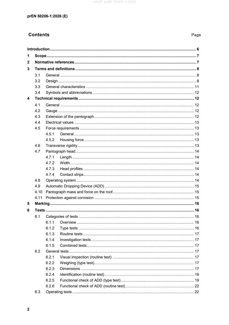
oSIST prEN 50206-1:2026 is a CENELEC draft European Standard for pantographs on main line railway vehicles. It specifies the general assembly characteristics of the pantograph and its control unit so they can collect current from the overhead contact line system, and it sets out the tests used to verify that behavior. It is written for pantograph suppliers, vehicle manufacturers, and railway customers who need to specify, design, verify, or accept these assemblies.
What does oSIST prEN 50206-1:2026 specify?
oSIST prEN 50206-1:2026 covers pantographs for main line vehicles, including the control unit that operates them. The scope ties the document to current collection from the overhead contact line system and to the tests needed to check that the pantograph and control unit perform as intended.
The document is organized into six clauses and five annexes. Clauses 3 to 6 cover terms and definitions, technical requirements, marking, and tests. Annex A gives friction tolerances, Annex B lists the tests, Annex C lists items for the customer specification, Annex D adds requirements for the Control Unit, and Annex E adds requirements for insulators.
| Annex | What it covers |
|---|---|
| Annex A | Kinematic structure friction tolerances |
| Annex B | Catalogue of tests |
| Annex C | Items to be specified in the customer specification |
| Annex D | Additional requirements for Control Unit |
| Annex E | Additional requirements for Insulators |
The scope also places related applications elsewhere: pantograph dielectric tests on the vehicle roof are handled by EN 50124-1, pantographs for isolated metros and light rail systems are handled by EN 50206-2, and third and fourth rail current collectors are handled by EN 50702.
What are the key requirements of oSIST prEN 50206-1:2026?
oSIST prEN 50206-1:2026 makes the customer specification central. Clause 4 states that general characteristics, environmental category, voltage and current values, contact forces, pantograph extension, head dimensions, ADD settings, corrosion protection, and several test conditions are to be defined there. In practice, this means the buyer or vehicle builder must state the operating envelope before a compliant design can be selected or tested.
Clause 4.2 and 4.3 link the pantograph to gauge and movement limits. The pantograph must fit the specified gauge in housed and operating positions, and the head trajectory over the working range is limited if the customer has not specified tighter values. This matters because a pantograph can only be accepted if it stays within the vehicle and infrastructure clearances.
Clause 4.5 and Annex A govern force behavior. Static contact forces measured during raising and lowering must stay within the friction tolerances in Annex A, and the housing force must keep the pantograph in the housed position up to maximum vehicle speed. Clause 4.6 then checks transverse rigidity by applying a 300 N lateral force and confirming that movement stays within the allowed limit and no permanent deformation appears.
Clause 4.8 and 6.3 define the operating motion. The document uses the times t0 to t4 to track the lowering sequence, from command to stowed position. The pantograph must break from the contact wire to the required dynamic clearance within 2.5 s, and the total lowering to dynamic insulated distance must be 3 s or less at maximum speed in both directions. For users, that means the pantograph has to clear the wire fast enough for neutral sections and other infrastructure constraints.
Clause 4.9 sets the function of the Automatic Dropping Device (ADD). The ADD must drop the pantograph immediately after a head failure, detect damaging events that could harm the overhead contact line, avoid added damage, and tolerate minor service damage without unnecessary operation. Clause 6 then gives laboratory and routine tests for ADD reaction time, leakage sensitivity, and closing performance.
Clauses 6.4 to 6.12 cover endurance, shock, vibration, air tightness, current collection, and heating. The pantograph must survive repeated raising and lowering, vibration and shock per EN 61373, leakage checks if it uses pneumatic actuation, current collection tests per EN 50317 and EN 50367, and heating tests under standstill or running conditions. These tests show whether the design is durable enough for service and whether it can carry current without damage.
Clause 5 requires clear marking. The pantograph must carry the manufacturer name, type designation, serial number, rated maximum current, standard reference, production date, and total mass excluding insulators. That supports traceability in production, maintenance, and acceptance.
What terms does oSIST prEN 50206-1:2026 define?
- Supplier - the manufacturer of the pantograph. This is the party responsible for design and declared performance.
- Customer - the operating authority or the vehicle manufacturer. This is the party that sets project-specific requirements.
- Control system - the apparatus that sends pneumatic or electric energy to the pantograph actuation to create a defined contact force. It is what makes the pantograph raise and lower correctly.
- Operating system - the device that provides the force to raise or lower the pantograph. It is central to timing, motion, and reliability.
- Automatic Dropping Device (ADD) - the device that initiates immediate lowering if the pantograph head fails. It is a safety function aimed at limiting damage.
- Static contact force - the upward vertical force from the pantograph head on the overhead contact line at standstill. It is the basic force setting used in verification.
- Housing force - the vertical force that keeps the pantograph in the housed position. It matters for safe retention at speed.
Who uses oSIST prEN 50206-1:2026?
oSIST prEN 50206-1:2026 is used by pantograph manufacturers, rolling stock builders, control unit suppliers, test laboratories, and railway operators. It is also relevant to quality managers and buyers who need to write a customer specification or check test evidence.
In practice, these users rely on it for design definition, procurement, type testing, routine production checks, vehicle integration, and current collection validation on real track. It also supports acceptance decisions for pantographs, control units, and related insulators.
What changed in oSIST prEN 50206-1:2026 from the previous edition?
oSIST prEN 50206-1:2026 supersedes EN 50206-1:2010 and its amendments and corrigenda. The document states these technical changes:
- updated normative references and definitions
- new tests for ADD, operating system, and lateral stiffness
- new annexes for control unit testing and insulators
- alignment of terms with EN 50317 and EN 50367
- deletion of Clauses 7, 8, and 9
- improved current-capacity acceptance criteria, lowering-time definition, and verification test conditions in relation to TSI ENE
Which standards are used with oSIST prEN 50206-1:2026?
| Standard | What it contributes |
|---|---|
| EN 12663-1 | Vehicle body structural requirements, used for pantograph mass and fixing-point loads |
| EN 15273 series / EN 15273-1 | Gauge and reference profile rules used for clearance checks |
| EN 50119 | Overhead contact line data, electrical clearances, and dynamic clearance references |
| EN 50125-1 | Environmental conditions for rolling stock and on-board equipment |
| EN 50163 | Supply voltages for traction systems |
| EN 50317 | Measurement requirements for dynamic interaction and current collection tests |
| EN 50367 | Technical compatibility criteria between pantographs and overhead contact lines |
| EN 50405 | Test methods for carbon contact strips |
| EN 60077-1 | General service conditions for electric equipment on rolling stock |
| EN 61373 | Shock and vibration tests for rolling stock equipment |
| EN 50124-1 | Insulation coordination and clearances/creepage distances |
| EN 50206-2 | Pantographs for metros and light rail vehicles |
| EN 50702 | Conductor rail current collectors |
| EN 50155 | Electronic equipment on rolling stock, used in Annex D |
| EN 50121-3-2 | EMC for rolling stock apparatus, listed in the bibliography for control units |
| EN 50716 / EN 50657 / EN IEC 62443-4-2 | Software and cybersecurity references used for control units in Annex D |
What does the oSIST prEN 50206-1:2026 document contain?
oSIST prEN 50206-1:2026 contains detailed test methods for visual inspection, weighing, dimensions, ADD function, operating timing, climatic behavior, endurance, shock, vibration, air tightness, degrees of freedom, housing force, current collection, and heating. It also includes figures for pantograph terminology, head dimensions, transverse rigidity, shock testing, and insulator design, plus tables for operating times, rigidity limits, and annex content.
The annexes add practical material for design and procurement: Annex B is a test catalogue, Annex C is the customer-specification checklist, Annex D extends the standard to the Control Unit, and Annex E gives additional design and test expectations for insulators. For engineers and buyers, that means the document is not just a definition of the pantograph - it is also a checklist for what must be specified, measured, and recorded before acceptance.
Relations
- Effective Date
- 23-Jan-2024
Get Certified
Connect with accredited certification bodies for this standard

IMQ S.p.A. (Certification)
Italian electrical product certification.

IRIS Certification (UNIFE)
International Railway Industry Standard certification.

SLG Prüf- und Zertifizierungs GmbH
German testing and certification body.
Sponsored listings
Frequently Asked Questions
oSIST prEN 50206-1:2026 is a draft published by the Slovenian Institute for Standardization (SIST). Its full title is "Railway applications - Rolling stock - Pantographs: Characteristics and tests - Part 1: Pantographs for main line vehicles". This standard covers: This document specifies the general assembly characteristics applied to pantographs and their control unit, to enable current collection from the overhead contact line system. It also specifies the tests the pantographs and their control unit need to perform. This document is not applicable to pantograph dielectric tests performed on the pantograph installed on the vehicle roof. Insulation coordination is covered in EN 50124 1. This document is not applicable to pantographs used on isolated metros and light rail systems. These pantographs are considered in EN 50206 2. This document is not applicable to third and fourth rail current collectors used on isolated metros and light rail systems. These pantographs are considered in EN 50702.
This document specifies the general assembly characteristics applied to pantographs and their control unit, to enable current collection from the overhead contact line system. It also specifies the tests the pantographs and their control unit need to perform. This document is not applicable to pantograph dielectric tests performed on the pantograph installed on the vehicle roof. Insulation coordination is covered in EN 50124 1. This document is not applicable to pantographs used on isolated metros and light rail systems. These pantographs are considered in EN 50206 2. This document is not applicable to third and fourth rail current collectors used on isolated metros and light rail systems. These pantographs are considered in EN 50702.
oSIST prEN 50206-1:2026 is classified under the following ICS (International Classification for Standards) categories: 29.280 - Electric traction equipment; 45.060.01 - Railway rolling stock in general. The ICS classification helps identify the subject area and facilitates finding related standards.
oSIST prEN 50206-1:2026 has the following relationships with other standards: It is inter standard links to SIST EN 50206-1:2011. Understanding these relationships helps ensure you are using the most current and applicable version of the standard.
oSIST prEN 50206-1:2026 is associated with the following European legislation: EU Directives/Regulations: 2016/797/EU; Standardization Mandates: M/591. When a standard is cited in the Official Journal of the European Union, products manufactured in conformity with it benefit from a presumption of conformity with the essential requirements of the corresponding EU directive or regulation.
oSIST prEN 50206-1:2026 is available in PDF format for immediate download after purchase. The document can be added to your cart and obtained through the secure checkout process. Digital delivery ensures instant access to the complete standard document.
Standards Content (Sample)
SLOVENSKI STANDARD
01-julij-2026
Železniške naprave - Tirna vozila - Pantograf: karakteristike in preskusi - 1. del:
Pantograf za železniška vozila na magistralnih progah
Railway applications - Rolling stock - Pantographs: Characteristics and tests - Part 1:
Pantographs for main line vehicles
Bahnanwendungen - Schienenfahrzeuge - Merkmale und Prüfungen von
Stromabnehmern - Teil 1: Stromabnehmer für Vollbahnfahrzeuge
Applications ferroviaires - Matériel roulant - Pantographes: Caractéristiques et essais -
Partie 1: Pantographes pour véhicules grandes lignes
Ta slovenski standard je istoveten z: prEN 50206-1:2026
ICS:
29.280 Električna vlečna oprema Electric traction equipment
45.060.01 Železniška vozila na splošno Railway rolling stock in
general
2003-01.Slovenski inštitut za standardizacijo. Razmnoževanje celote ali delov tega standarda ni dovoljeno.
EUROPEAN STANDARD DRAFT
prEN 50206-1
NORME EUROPÉENNE
EUROPÄISCHE NORM
May 2026
ICS 29.280 Will supersede EN 50206-1:2010
English Version
Railway applications - Rolling stock - Pantographs:
Characteristics and tests - Part 1: Pantographs for main line
vehicles
Applications ferroviaires - Matériel roulant - Pantographes: Bahnanwendungen - Schienenfahrzeuge - Merkmale und
Caractéristiques et essais - Partie 1: Pantographes pour Prüfungen von Stromabnehmern - Teil 1: Stromabnehmer
véhicules grandes lignes für Vollbahnfahrzeuge
This draft European Standard is submitted to CENELEC members for enquiry.
Deadline for CENELEC: 2026-08-21.
It has been drawn up by CLC/SC 9XB.
If this draft becomes a European Standard, CENELEC members are bound to comply with the CEN/CENELEC Internal Regulations which
stipulate the conditions for giving this European Standard the status of a national standard without any alteration.
This draft European Standard was established by CENELEC in three official versions (English, French, German).
A version in any other language made by translation under the responsibility of a CENELEC member into its own language and notified to
the CEN-CENELEC Management Centre has the same status as the official versions.
CENELEC members are the national electrotechnical committees of Austria, Belgium, Bulgaria, Croatia, Cyprus, the Czech Republic,
Denmark, Estonia, Finland, France, Germany, Greece, Hungary, Iceland, Ireland, Italy, Latvia, Lithuania, Luxembourg, Malta, the
Netherlands, Norway, Poland, Portugal, Republic of North Macedonia, Romania, Serbia, Slovakia, Slovenia, Spain, Sweden, Switzerland,
Türkiye and the United Kingdom.
Recipients of this draft are invited to submit, with their comments, notification of any relevant patent rights of which they are aware and to
provide supporting documentation.
Warning : This document is not a European Standard. It is distributed for review and comments. It is subject to change without notice and
shall not be referred to as a European Standard.
European Committee for Electrotechnical Standardization
Comité Européen de Normalisation Electrotechnique
Europäisches Komitee für Elektrotechnische Normung
CEN-CENELEC Management Centre: Rue de la Science 23, B-1040 Brussels
© 2026 CENELEC All rights of exploitation in any form and by any means reserved worldwide for CENELEC Members.
Project: 79344 Ref. No. prEN 50206-1:2026 E
Contents Page
Introduction . 6
1 Scope . 7
2 Normative references . 7
3 Terms and definitions . 8
3.1 General . 8
3.2 Design . 8
3.3 General characteristics . 11
3.4 Symbols and abbreviations . 12
4 Technical requirements . 12
4.1 General . 12
4.2 Gauge . 12
4.3 Extension of the pantograph . 12
4.4 Electrical values . 13
4.5 Force requirements . 13
4.5.1 General . 13
4.5.2 Housing force . 13
4.6 Transverse rigidity . 13
4.7 Pantograph head . 14
4.7.1 Length . 14
4.7.2 Width . 14
4.7.3 Head profiles . 14
4.7.4 Contact strips . 14
4.8 Operating system . 14
4.9 Automatic Dropping Device (ADD) . 15
4.10 Pantograph mass and force on the roof. 15
4.11 Protection against corrosion . 15
5 Marking . 16
6 Tests . 16
6.1 Categories of tests . 16
6.1.1 Overview . 16
6.1.2 Type tests . 16
6.1.3 Routine tests . 17
6.1.4 Investigation tests . 17
6.1.5 Combined tests . 17
6.2 General tests . 17
6.2.1 Visual inspection (routine test) . 17
6.2.2 Weighing (type test) . 17
6.2.3 Dimensions . 17
6.2.4 Identification (routine test) . 19
6.2.5 Functional check of ADD (type test) . 19
6.2.6 Functional check of ADD (routine test) . 22
6.3 Operating tests . 22
6.3.1 Measurement of friction of kinematic structure at ambient temperature (routine
test) . 22
6.3.2 Checking of operating system in the laboratory (type test) . 22
6.3.3 Checking of the operating system of the pantograph (routine test) . 24
6.3.4 Operating climatic test (type test) . 25
6.3.5 Measurement of mean static contact force at ambient temperature (investigation
test) . 25
6.3.6 Measurement of static contact force after installation of the pantograph on the
vehicle (combined test) . 25
6.4 Endurance tests . 25
6.4.1 Raising/lowering operations (type test) . 25
6.4.2 Pantograph head suspension (type test) . 26
6.4.3 Resistance to vibrations. 26
6.5 Resistance to shocks (type test) . 27
6.6 Transverse rigidity test (type test) . 27
6.7 Air tightness tests . 29
6.7.1 General . 29
6.7.2 Air tightness type tests (type test) . 29
6.7.3 Routine air tightness test (routine test) . 30
6.7.4 Air tightness climatic test (type test) . 31
6.8 Measurement of degrees of freedom of pantograph head (routine test) . 31
6.8.1 General . 31
6.8.2 Rotational degree of freedom of the pantograph head (routine test) . 32
6.8.3 Freedom of motion of the pantograph head suspension (routine test) . 32
6.9 Measurement of housing force (type test) . 32
6.10 Current collection tests (combined test) . 32
6.11 Heating tests . 32
6.11.1 Heating tests: rated and maximum current, vehicle at standstill (supplementary
type test) . 32
6.11.2 Heating test: simulation of running vehicle (supplementary type test) . 33
6.11.3 Field test (combined test) . 33
6.12 Check of operating system at maximum speed (combined test) . 34
Annex A (normative) Kinematic structure friction tolerances . 35
Annex B (normative) List of tests . 36
Annex C (informative) Items to be specified in customer specification . 37
Annex D (informative) Additional requirements for Control Unit. 38
D.1 Purpose . 38
D.2 Type test with control unit and related pantograph . 38
D.2.1 General . 38
D.2.2 Air tightness and consumption climatic test (type test) (addition to 6.7.3) . 38
D.2.3 Endurance test - Operation within working range (type test) (addition to 6.4.1.2) . 38
D.2.4 Check of operating system at standstill (type test) (addition to 6.3.2) . 39
D.2.5 Checking of the operating system of the pantograph (type test) (addition to 6.3.3) 39
D.2.6 Functional check of A.D.D. (addition to 6.2.5) . 39
D.3 Type tests for control unit . 39
D.3.1 Endurance test (supplementary type test) . 39
D.3.2 Other tests (supplementary type tests) . 39
Annex E (informative) Additional requirements for Insulators . 41
E.1 Purpose . 41
E.2 Design . 41
E.2.1 Standards application . 41
E.2.2 Fin design (best practice) . 42
E.2.3 Bushing and spacer designs (best practice) . 44
E.2.4 Global design check (type tests) . 45
E.2.5 Marking . 45
E.3 Performances tests (type tests) . 45
E.3.1 Stress evaluation . 45
E.3.2 Bending test (also called cantilever test) . 46
E.3.3 Maximum tensile stress test (type test) . 46
E.3.4 Nominal tensile stress test (type test) . 47
E.3.5 Dielectric test (type test) . 47
E.3.6 Other tests (type test) . 47
Bibliography . 48
Figures
Figure 1-– Pantograph terminology (to be updated) . 11
Figure 2 — Pantograph head dimension . 18
Figure 3 — Illustration of the EN 50206 series tests compared to EN 50317:2025 and TSI
LOC&PAS requirements . 23
Figure 4 — Resistance to shock test principle . 27
Figure 5 — Transverse Rigidity . 27
Figure 6 — Transverse rigidity test principle . 28
Figure A.1 — Kinematic structure friction tolerances (grey area) . 35
Figure E.1 — Fin distance. 43
Figure E.2 — Alternate fins dimensions . 43
Figure E.3 — Fin slope . 44
Figure E.4 — Minimal design requirements of bushing . 44
Figure E.5 — Fixing of resin based insulator . 45
Figure E.6 — Default position of insulator on bending test machine (left: 2 points fixing
insulator; right: 4 points fixing insulator) . 46
Tables
Table 1 — Design definitions . 9
Table 2 — Rising and lowering times . 24
Table 3 — centre of collector head values. 28
Table B.1 — Catalogue of tests . 36
Table E.1 — Applicable standards . 42
European foreword
This document (prEN 50206-1:2026) was prepared by SC 9XB, Electromechanical material on board rolling
stock, of Technical Committee CENELEC TC 9X, Electrical and electronic applications for railways.
This document is currently submitted to the Enquiry.
The following dates are proposed:
• latest date by which the existence of this (doa) dav + 6 months
document has to be announced at national level
• latest date by which this document has to be (dop) dav + 12 months
implemented at national level by publication of
an identical national standard or by
endorsement
• latest date by which the national standards (dow) dav + 36 months
conflicting with this document have to be (to be confirmed or
withdrawn modified when voting)
This document will supersede EN 50206-1:2010 and all of its amendments and corrigenda (if any).
— update of normative references and definitions;
— definition of new tests for ADD, operating system and lateral stiffness;
— definition of new annexes for test of control units and insulators;
— adjustment of terms to EN 50317 and EN 50367;
— deletion of Clauses 7, 8 and 9;
— update of normative references.
The following changes are describing the relation to TSI ENE:
— working range: changes are not affecting the working range;
— current capacity: test acceptance criteria improved;
— lowering: time definition improved;
— verification: test conditions improved.
This document has been prepared under a standardization request addressed to CENELEC by the
European Commission. The Standing Committee of the EFTA States subsequently approves these
requests for its Member States.
Introduction
The electrical power supply of an electric traction unit is achieved by the collection of current from one or
more contact wires by means of one or more roof-mounted pantograph(s), installed on the unit.
The contact strips of the pantograph which brush along the contact wire accommodate the transmission of
power.
The pantograph and the overhead contact line system form two oscillating sub-systems which can be
displaced. There exists a unilateral sliding contact between them, which shall ensure continuous contact.
Their design shall allow for minimum wear of both sub-systems when used.
1 Scope
This document specifies the general assembly characteristics applied to pantographs and their control unit,
to enable current collection from the overhead contact line system. It also specifies the tests the
pantographs and their control unit need to perform.
This document is not applicable to pantograph dielectric tests performed on the pantograph installed on the
vehicle roof. Insulation coordination is covered in EN 50124-1.
This document is not applicable to pantographs used on isolated metros and light rail systems. These
pantographs are considered in EN 50206-2.
This document is not applicable to third and fourth rail current collectors used on isolated metros and light
rail systems. These pantographs are considered in EN 50702.
2 Normative references
The following documents are referred to in the text in such a way that some or all of their content constitutes
requirements of this document. For dated references, only the edition cited applies. For undated references,
the latest edition of the referenced document (including any amendments) applies.
EN 12663-1:2010+A2:2023, Railway applications - Structural requirements of railway vehicle bodies - Part
1: Locomotives and passenger rolling stock (and alternative method for freight wagons)
EN 15273 (all parts), Railway applications
EN 15273-1:2025, Railway applications - Gauges - Part 1: General - Common rules for rolling stock and
infrastructure
EN 50119:2020, Railway applications - Fixed installations - Electric traction overhead contact lines
EN 50125-1:2014, Railway applications - Environmental conditions for equipment - Part 1: Rolling stock
and on-board equipment
EN 50163:2004, Railway applications - Supply voltages of traction systems
EN 50317:2025, Railway applications - Current collection systems - Requirements for and validation of
measurements of the dynamic interaction between pantograph and overhead contact line
EN 50367:2020, Railway applications - Fixed installations and rolling stock - Criteria to achieve technical
compatibility between pantographs and overhead contact line
EN 50405:2015, Railway applications - Current collection systems - Pantographs, testing methods for
carbon contact strips
EN 60077-1:2017, Railway applications - Electric equipment for rolling stock - Part 1: General service
conditions and general rules (IEC 60077:2017)
EN 61373:2010, Railway applications - Rolling stock equipment - Shock and vibration tests (IEC
61373:2010)
As impacted by EN 50163:2004/A1:2007, EN 50163:2004/Corrigendum May 2010, EN 50163:2004/AC:2013,
EN 50163:2004/A2:2020, EN 50163:2004/A3:2022.
As impacted by EN 50367:2020/A1:2022 and EN 50367:2020/A2:2025.
As impacted by EN 50405:2015/A1:2016.
3 Terms and definitions
For the purposes of this document, the following terms and definitions apply.
ISO and IEC maintain terminological databases for use in standardization at the following addresses:
• IEC Electropedia: available at https://www.electropedia.org/
• ISO Online browsing platform: available at https://www.iso.org/obp
3.1 General
3.1.1
supplier
manufacturer of the pantograph
3.1.2
customer
either operating authority or vehicle manufacturer
3.1.3
Pantograph (see Figure 1)
apparatus for collecting current from one or more contact wires, formed of a hinged device designed to
allow vertical movement of the pantograph head
Note 1 to entry: It consists of a base frame, an operating system, a kinematic structure and a pantograph head. It is
of variable geometry. In the “operating” position, the apparatus is entirely or partly under voltage. It is electrically
insulated only generally at its interfaces, on the vehicle roof. It enables current to be transmitted from the overhead
contact line system to the vehicle electrical system
[SOURCE: IEC 60050-811:2017, 811-32-02, modified – Note 1 to entry added.]
3.1.4
control system
apparatus that transmits the necessary energy (pneumatic or electric) to the pantograph actuation to
generate a defined contact force between pantograph contact strip and contact line
3.2 Design
The definitions in Table 1 are related to Figure 1, except items 9, 15, 16, 17, 18.
Table 1 — Design definitions
Def. Term Item Definition
No. No.
3.2.1 kinematic structure 1 articulated structure which enables the
collector head to move in a vertical
direction with respect to the base frame of
the pantograph
3.2.2 base frame 2 fixed part of the pantograph which supports
the kinematic structure and is fixed to the
vehicle roof (e.g. using insulators)
3.2.3 pantograph head 3 part of the pantograph comprising the
contact strips and their mountings, horns
and possibly a suspension
[SOURCE: IEC 60050-811:2017, 811–32–
05]
3.2.4 contact strip 4 replaceable wearing part of the pantograph
head which interfaces with the contact wire
[SOURCE: IEC 60050-811:2017, 811–32–
06]
3.2.5 horns 5 ends of the pantograph head which ensure
smooth engagement with the contact wire
3.2.6 pantograph head length 6 dimension of pantograph head measured
transversely in the horizontal plane in
relation to the vehicle
3.2.7 pantograph head width 7 dimension of pantograph head measured
longitudinally in relation to the vehicle
3.2.8 pantograph head height 8 vertical distance between the lowest point
of the horns and the upper most point of the
contact strips
3.2.9 pantograph head pivot 9 pitching axis of the pantograph head
3.2.10 length of contact strips 10 total length of wearable material intended
for normal interaction measured
transversely in relation to the vehicle
3.2.11 height at “lower operating 11 vertical minimum distance above housed
position” height at which the pantograph is designed
to collect current
3.2.12 height at “upper 12 vertical maximum distance above the
operating position” housed height at which the pantograph is
designed to collect current
3.2.13 working range 13 difference between the “upper operating
position” height and the “lower operating
position” height
Def.
Term Item Definition
No. No.
3.2.14 housed height above 14 vertical distance between top of insulators
insulators and the upper surface of the contact strips
or any other part of the pantograph
structure if higher (pantograph being in the
housed position)
3.2.15 pantograph insulation 15 minimum distance between the bottom of
distance when raised the insulator and the closest conductive
component of the pantograph in every
height when raised
3.2.16 operating system 16 device which provides a force to raise or to
lower the pantograph
3.2.17 maximum extension 17 maximum extended height to mechanical
stops (without any device which will limit
the pantograph extension within the
working range)
3.2.18 limited maximum 18 reduced extension allowed by intermediate
extension mechanical stops
3.2.19 housed height with 19 vertical distance between the pantograph
insulators mounting plane on the roof of the vehicle
(under insulator) and the upper surface of
the contact strips or any other part of the
pantograph structure if higher (pantograph
being in the housed position)
3.2.20 longitudinal movement 20 Maximum longitudinal movement between
“lower operating position” and “upper
operating position”
3.2.21 lateral movement free of 21 Maximum right and left movement of
force pantograph until “upper operating position”
compared to central axis, due to internal
tolerances and kinematic
3.2.22 lateral pantograph semi- 22 Maximum right and left width of pantograph
width at “upper operating position” compared to
central axis, due to internal tolerances and
kinematic
3.2.23 pantograph insulation 15’ minimum distance between the bottom of
distance when lowered the insulator and the closest conductive
component of the pantograph in every
height when lowered (useful if a pantograph
can live because connected to another
pantograph in contact with overhead line)
Figure 1 — Pantograph terminology (to be updated)
The sketch in Figure 1 is an example only and does not exclude other types of pantographs (diamond type,
for example).
NOTE Value ht and h´0 are used by gauging calculation according to EN 15273 series.
3.3 General characteristics
3.3.1
rated voltage
the nominal voltage at which the pantograph is designed to function
3.3.2
rated current, vehicle at standstill
average value of that current withstood for 30 min by the pantograph at standstill
3.3.3
maximum current, vehicle at standstill
value of that current withstood by the pantograph at standstill for a given time
3.3.4
rated current, vehicle running
continuous current transfer capacity of the pantograph
3.3.5
static contact force
vertical force exerted upward by the pantograph head on the overhead contact line at standstill
[SOURCE: EN 50367:2020, 3.21]
3.3.6
nominal static contact force
specified set point for the static contact force
3.3.7
mean static contact force
average of the actual values of static contact forces evaluated as follows: the static contact forces are
measured continually within the working range during raising (F) and lowering (F) operation. By
r l
convention, the mean static contact force at any point is equal to
FF+
rl
3.3.8
mean cord force
statistical mean value of cord force measured at the pantograph head, the latter not touching the contact
line, being equal to the sum of static contact force and the aerodynamic force caused by the air at the
considered speed for a given height of contact points
3.3.9
contact force
vertical force applied by the pantograph to the contact wire(s)
Note 1 to entry: The contact force is the sum of forces of all contact points of a pantograph.
Note 2 to entry: The contact force is measured perpendicular to the contact plane.
[SOURCE: EN 50317:2025, 3.1.4]
3.3.10
housing force
force applied vertically to the pantograph head to maintain the whole pantograph in housed position
3.4 Symbols and abbreviations
For the purpose of this document, the following symbols and abbreviations apply.
Fo natural transverse frequency of the pantograph
AC Alternating Current
ADD Automatic Dropping Device
CAD Computer Aided Design
DC Direct Current
EPCU Electro-Pneumatic Control Unit
PCU Pneumatic Control Unit
4 Technical requirements
4.1 General
All general characteristics are given in the customer specifications. Unless otherwise specified,
environmental conditions are defined in EN 50125-1. The category of environment has to be specified by
the customer.
4.2 Gauge
The pantograph, at housed position and operating position, shall comply with the gauge specified in the
customer specifications or shall be in accordance with EN 50367:2020 and the EN 15273 series.
The encroachment of the contact strips above reference profile according EN 15273-1 shall not exceed the
value defined in EN 15273-1:2025, B.4 under all operating conditions.
4.3 Extension of the pantograph
The customer specifications shall state the values in relationship with items 10 to 13 in Table 1. In the
absence of specifications in the tender documents, when the pantograph is raising or lowering, the
pantograph head trajectory over the working range shall be within tolerance of 100 mm in the longitudinal
direction, and ± 10 mm in the lateral direction in relation to the vertical line.
4.4 Electrical values
The typical supply voltages of traction systems are specified in EN 50163. The typical values for insulation
coordination are specified in EN 50124-1.
Values defined in 3.3.2 to 3.3.4 include all relevant voltage systems, the overvoltage category and pollution
degree, and therefore the minimum value for clearance distance and creepage values for the insulation for
operating shall be given in the customer specifications.
For insulated end horns which stick into the clearance distance of the pantograph, the following formula
may apply:
ll
clearance__is creepage is
+> 1
ll
clearance__nominal creepage nominal
where
lclearance is is the clearance realized;
l is the clearance required (without additional creepage);
clearance nominal
lcreepage is is the creepage realized;
l is the creepage required (without additional creepage).
creepage nominal
NOTE It is an approximation of Paschen's law where breakdown voltage is supposed linear in the air and for
normal altitudes.
4.5 Force requirements
4.5.1 General
Static contact forces measured during raising and lowering shall lie within the boundaries defined in
Annex A.
Operating requirements for static contact force, mean cord force and mean contact force shall follow the
requirements in EN 50367:2020 if not specified in the customer specifications.
4.5.2 Housing force
The housing force shall prevent the pantograph from leaving the housed position at all speeds up to
maximum speed of the vehicle. The housing force is the force required to maintain the pantograph head at
the distance defined in the chapter 6.9 from the housed position.
The housing force may be agreed between the customer and the supplier. Alternatively, provision may be
made for the fitting of a holding down device.
4.6 Transverse rigidity
The rigidity of the raised pantograph against lateral forces such as lateral acceleration forces, lateral wind
forces, friction forces of the contact wire(s) etc. shall be tested to ensure the fulfilment of the gauge
requirements.
The pantograph is raised at the upper operating position or at the operating position defined by the customer
with static load and without any compression of the suspension. A transverse force of 300N is exerted at
the extremity of the upper arm on the pantograph head pivot at the upper operating position or at the
operating position defined by the customer and after removing the transversal gap of the pantograph head
(2nd cycle), the lateral movement of the pantogaph head localized on the extremity of the horn shall not
exceed the value defined in 6.6 and no permanent deformation shall occur.
4.7 Pantograph head
4.7.1 Length
If not specified in the customer specification, lengths defined in EN 50367:2020 shall be used.
4.7.2 Width
The pantograph head width shall be defined according to the type of suspension, the number of wear strips
and the system characteristics of the overhead contact line system. If not specified in the customer
specification, widths defined in EN 50367 shall be used. If not defined in EN 50367 the outline for non-
continuous pantograph head profiles under spring deflection shall respect further geometrical requirements
to ensure a smooth transition of an incoming wire.
4.7.3 Head profiles
If not specified in the customer specification, the pantograph head outline profiles and maximum allowable
tilt defined in EN 50367:2020 shall be used.
In the case of contact wire transition or crossing which may result in lowered incoming and outgoing contact
wires, the pantograph profile shall ensure that incoming or outgoing contact wires shall come in contact
with contact strips or end horns only. No contact of the incoming and outgoing contact wires with any other
part of the pantograph structure shall be possible.
The pantograph profile shall be continuous at all times independent of the point of contact force including
lateral deviation. The pantograph profile shall not exhibit gaps or breaks under lateral deviation of the point
of contact force.
4.7.4 Contact strips
If not specified in the customer specification wear strip material, maximum current at standstill and under
running conditions defined in EN 50367:2020 shall be used. Applicable testing methods according to
EN 50405 shall be used.
4.8 Operating system
The following times are defined:
— t0 – command «pantograph down»
— t1 – control system of the pantograph is activated to lower (optional)
— t2 – contact strips detach from contact wire
— t3 – defined electrical clearance achieved
— t4 – stowed position of pantograph
The operating system shall be designed to ensure, at standstill and up to the maximum speed of the traction
unit, a break from the contact wire, within a time measured and defined in the chapter 6.3.2, over the
minimum clearance distance. This time begins when the control system of the pantograph for lowering is
activated (t1) and ends when the contact strips reach the minimum dynamic clearance to the contact wire
(t3).
This requirement shall be met in both directions of travel.
The minimum dynamic clearance shall be used:
— EN 50119:2020, Table 2 – Typical electrical clearances, column “Dynamic”;
— specification of the customer.
If the pneumatic control system is not located on the pantograph, the supplier shall specify the maximum
permissible length and the maximum permissible cross-section (or the maximum permissible volume) of
the compressed air pipes between the control unit and the pantograph
4.9 Automatic Dropping Device (ADD)
The automatic dropping device shall initiate the immediate lowering of the pantograph in the event of
pantograph head failure.
Impact or damage occurring to contact strips liable to cause subsequent damage to overhead contact line
system shall be detected by ADD. Impacts or damages to other parts of the pantograph head like horns
can be included in the ADD.
When designing, the following characteristics shall be taken into account:
— ADD reaction time;
— ADD failure to safe condition;
— ADD self test in workshop;
— ADD reliability;
— pantograph integrity after work of ADD
— impact of varying climate conditions, especially in regard to min. and max. ambient temperatures, on
the A.D.D. system (e.g. the reliability and reaction time of an ADD valve)
The ADD system shall be designed to ensure that minor damage to the contact strips as may be
experienced in daily service shall not cause operation of ADD system.
The ADD shall not cause additional damage to the pantograph.
4.10 Pantograph mass and force on the roof
The supplier shall provide the mass of the pantograph and its centre of gravity at upper operating and
housed positions. The data shall be available either with or without insulators.
The supplier shall also provide the maximum load at every fixing point according to EN 12663-1. In addition,
the supplier shall specify all relevant parameters to enable the calculation of the maximum efforts at every
fixing point.
NOTE Aerodynamic forces are not taken into account.
4.11 Protection against corrosion
The specifications regarding the application requirements and type of corrosion protection shall be given in
the customer specifications.
In addition to the protection against common corrosive effects e.g. on vehicle structures, the corrosion
protection of the pantograph shall be taken into account:
a) effects of electrochemical corrosion between conductive and therefore unprotected surfaces of
different metals being in touch with each other
b) crevice corrosion for telescoping tubular structures (including bearings) caused by concentration of
cleaning substances for the carbody
The evaluation of above mentioned effects might be done for
a) by choice of materials
b) by special corrosive tests if demanded by the customer for pure cleaning substances specified by the
customer
5 Marking
As a minimum the following shall be labelled on the pantograph:
— manufacturer's name;
— manufacturer’s type designation of pantograph
— manufacturer’s serial number;
— rated max current (continuously) (AC or DC)
— standard
— production date
— total mass (excl. insulators).
6 Tests
6.1 Categories of tests
6.1.1 Overview
There are four categories of tests:
— type tests;
— routine tests;
— investigation tests;
— combined tests.
The above tests are described in 6.1.2 to 6.1.5.
Annex B summarizes the tests which shall be performed.
Annex C sums up the list of items to be specified by customer.
Annex D is adding requirement for Control Unit design and tests if specified by customer.
6.1.2 Type tests
This European Standard distinguishes the basic model of a pantograph from further developments of the
basic model of the same pantograph. Further developments may incorporate modifications to the basic
design which shall be considered to be covered by the existing relevant type tests. This is provided that
any such changes can be demonstrated to be at least equal to the basic design through calculation or
operational experience of at least two years on a European Railway network, and with technical
requirements at least equal to those for which the basic model was designed.
Equipment in current manufacture shall be considered to have satisfied the type tests and shall be
exempted from them, if the manufacturer provides signed reports of type tests already made on identical
apparatus constructed previously.
Supplementary type tests shall be required if they are requested in the customer specification and after
agreement with the supplier.
6.1.3 Routine tests
Routine tests shall be carried out to verify that the properties of a product correspond to those measured
during the type test. Routine tests shall be performed by the supplier on each equipment. For certain
apparatus, after agreement between customer a
...