

oSIST prEN 50762-1:2026
(Main)Secondary batteries for light means of transport - Part 1: Test specifications for performance and durability aspects for lithium-ion and sodium-ion batteries
- Abstract
This European standard specifies test procedures for performance and durability aspects of light means of transport (LMT) batteries. These are sealed batteries with a maximum weight of 25 kg that are specifically designed to provide electric power for the traction of wheeled vehicles that can be propelled by an electric motor alone or by a combination of motor and human power, including type-approved vehicles of category L within the meaning of Regulation (EU) No 168/2013 of the European Parliament and of the Council, and that is not an electric vehicle battery. The scope of this document is restricted to lithium-ion batteries.
LMT batteries contain at least the following general classes:
• Batteries of L-category vehicles referred to in Article 2 of Regulation EU 168/2013 of the European Parliament and of the Council (e.g., batteries for light motorcycles, trikes and quads), where the battery weight is less than 25 kg.
• Batteries for EPACs (electronically power assisted cycle) with or without type approval
• Batteries for micro mobility devices like e.g., e-kick-scooters, hoverboards, self-balancing vehicles…
Batteries above 25 kg for mobility are not in the scope of this standard, even though they may be used in L category vehicles (e.g. L7 category). Batteries for toys are also not in the scope of this standard based on the recital 15 of (EU) 2023/1542: "Batteries used for traction in wheeled vehicles considered to be toys within the meaning of Directive 2009/48/EC of the European Parliament and of the Council, should, for the purposes of this Regulation, not be considered to be LMT batteries, but to be portable batteries."
For reused, remanufactured, repaired and repurposed (here further called “R”) batteries the same procedures have to be applied. The tests listed here have to be conducted and documented. If this is not possible, equivalent tests have to be performed. However, this document does not aim to specify detailed test procedures specifically for these kinds of “R”-batteries.
- Status
- Not Published
- Public Enquiry End Date
- 31-Oct-2026
- Technical Committee
- ISCB - Secondary cells and batteries
- Current Stage
- 4020 - Public enquire (PE) (Adopted Project)
- Start Date
- 31-Aug-2026
- Due Date
- 18-Jan-2027
- Completion Date
- 28-Sep-2026

oSIST prEN 50762-1:2026 is a draft European Standard published by SIST and prepared by CENELEC for secondary batteries used in light means of transport (LMT). It specifies test procedures for performance and durability of lithium-ion and sodium-ion LMT batteries, so manufacturers, laboratories, and buyers can compare batteries within the same application group. It is written for sealed batteries up to 25 kg used in traction applications such as EPACs, personal mobility devices, electrically powered wheelchairs, and certain category L vehicles.
What does oSIST prEN 50762-1:2026 specify?
oSIST prEN 50762-1:2026 specifies how to test LMT batteries for performance and durability, how to calculate the reported values, and how to document the results. The standard also defines which battery applications belong to group A and group B, because the two groups use different test sequences and their results are not comparable.
The scope covers sealed LMT batteries with a maximum weight of 25 kg that are designed to provide electric power for wheeled vehicles propelled by an electric motor alone or by a combination of motor and human power, including type-approved vehicles of category L. It excludes batteries above 25 kg for mobility and batteries for toys. Re-used, remanufactured, repaired, and repurposed batteries are also included, using the same procedures or equivalent tests where needed.
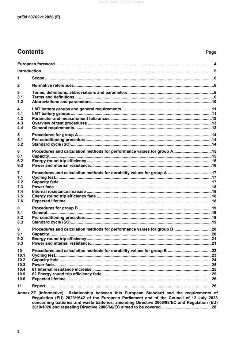
The document is organized into the following main parts:
- Clause 1 - Scope
- Clause 2 - Normative references
- Clause 3 - Terms, definitions, abbreviations and parameters
- Clause 4 - LMT battery groups and general requirements
- Clauses 5-7 - Procedures, performance calculations, and durability calculations for group A
- Clauses 8-10 - Procedures, performance calculations, and durability calculations for group B
- Clause 11 - Report
- Annex ZZ - Relationship with Regulation (EU) 2023/1542
What are the key requirements of oSIST prEN 50762-1:2026?
oSIST prEN 50762-1:2026 requires laboratories to test batteries under controlled conditions, with the battery supplier providing enough technical information to make the test setup repeatable. The main practical point is that the battery must be tested in the same way the document describes, or the reported performance and durability values are not comparable across manufacturers.
Grouping and test setup
Clause 4.1 divides LMT batteries into group A and group B according to their application. Group A covers applications such as EPACs, L1e-A and L1e-B vehicles designed to pedal, personal eTransporters, electrically powered wheelchairs and scooters, and other remaining applications. Group B covers applications such as L-cat vehicles not designed to pedal, off-road motorcycles, cargo eTransporters, and golf carts when they are not classified as industrial batteries. The results for group A and group B are not comparable, so the group matters when comparing products.
Clause 4.4 requires a technical data sheet with the interface parts, the way the battery is run on the test bench, the charging method for rated capacity testing, and any relevant communication protocols. The device under test has to be measured through its application interface, all tests are performed at room temperature (RT), and original samples used for testing must be less than four months old. In practice, this fixes the test conditions and sample condition before any result can be trusted.
Measurement accuracy and recording
Clause 4.2 sets the measurement tolerances for voltage, current, temperature, time, and mass, and it also sets how often values must be recorded. Group A requires recordings at least every 5 % of the estimated charge or discharge time, while group B requires recordings in 1 % steps. This means the lab needs calibrated equipment and enough data logging to reconstruct the test.
Group A procedures and performance values
Clauses 5 and 6 define the group A pre-conditioning and performance tests. The battery is first conditioned with at least three standard cycles (SC), where each SC consists of a standard discharge (SDCH) followed by a standard charge (SCH). The standard discharge uses C/2 or, if needed, 75 % of the maximum continuous discharge rate; the standard charge uses C/3 or, if needed, 75 % of the maximum charge rate, and the cut-off current defaults to C/10 if it is not declared.
Clause 6 then defines how to derive the group A performance values. Capacity and energy round trip efficiency (RTE) are taken from the last SC of the pre-conditioning sequence, while power and internal resistance are measured by a separate pulse method. The calculations are done on two DUTs, and the final reported value is selected from those two results according to the property being measured.
Group A durability values
Clauses 7.1 to 7.6 cover the cycling test and the durability outputs for group A. The battery is cycled until 350 SCs are reached or until capacity falls to 80 % of beginning of life (BOL) capacity, whichever comes first. The document then derives capacity fade, power fade, internal resistance increase, energy round trip efficiency fade, and expected lifetime. For expected lifetime, the document allows extrapolation, but the result is limited so that it does not run far beyond the measured cycling data.
Group B procedures and performance values
Clauses 8 and 9 cover group B, which uses a different pre-conditioning and test sequence. Group B requires at least one SC before testing, a rest period of at least 30 min after each full charge or full discharge and each targeted change in charge level, and a stable open circuit voltage (OCV) after rest. The SC for group B uses C/3 discharge and C/3 charge, or the maximum allowable rate if the C/3 value would exceed it.
Clause 9 defines capacity, RTE, power, and internal resistance for group B. These values are measured on one DUT, and the pulse test for power and internal resistance uses a discharge pulse after the battery has been brought to 50 % of rated capacity. For multiple-pack systems, the measurement applies to each battery pack individually, not to the complete system.
Group B durability values
Clauses 10.1 to 10.6 define the group B cycling test and durability calculations. The battery is cycled at C/3 until one of the stop criteria is reached, with performance checks at 100, 200, 300, and 350 cycles. The test stops at 350 cycles or when capacity falls to 80 % of BOL capacity. The durability outputs are capacity fade, power fade, internal resistance increase, energy round trip efficiency fade, and expected lifetime, with the lifetime result again limited by the measured data.
What terms does oSIST prEN 50762-1:2026 define?
- Light means of transport battery (LMT battery) - A sealed battery weighing 25 kg or less, designed to supply traction power for wheeled vehicles, including category L vehicles, and not an electric vehicle battery.
- Battery management system (BMS) - The electronic system that monitors or manages the battery state, calculates secondary data, reports it, and can influence safety, performance, or service life.
- Beginning of life (BOL) - The reference starting point used for performance and fade calculations before cycling aging reduces the battery values.
- Energy round trip efficiency (RTE) - The ratio between discharge energy and the energy needed to recharge the battery to the initial charge level.
- Standard cycle (SC) - The defined discharge-and-charge sequence used to set a common starting condition and to calculate performance values.
- Device under test (DUT) - The battery sample being tested according to the standard.
- R-battery - A re-used, repurposed, or remanufactured battery.
Who uses oSIST prEN 50762-1:2026?
oSIST prEN 50762-1:2026 is used by battery manufacturers, pack integrators, and vehicle makers that need to qualify LMT batteries for products such as EPACs, e-kick-scooters, hoverboards, self-balancing vehicles, electrically powered wheelchairs, and category L vehicles. It matters when they need to compare designs, define a technical data sheet, or check whether performance claims are based on the same test method.
Test laboratories and conformity assessment bodies use the standard to run the measurements, calculate the reported values, and write the test report. Quality managers and buyers use it to understand what data they should request and how to compare different suppliers on the same basis.
The standard is also relevant where evidence is needed for the battery-related requirements of Regulation (EU) 2023/1542, because Annex ZZ links the test clauses to those legal requirements.
Which standards are used with oSIST prEN 50762-1:2026?
- EN 61960-3:2017 - The only normative reference; it is used to verify rated capacity.
- EN 15194:2017+A1:2023 - Named in the group A classification for EPAC applications.
- EN 17860-1:2024 - Named in the group A classification for carrier cycles.
- IEC 63281-1:2023 - Named for personal eTransporters and cargo eTransporters in the group tables.
- EN 12184:2022 - Named for electrically powered wheelchairs and scooters in group A.
- EN 62620:2015 - Source used for the BMS definition.
- ISO 21498-2:2021 - Source used for the RT definition.
- IEC 60050-482:2004 - Source used for the nominal voltage definition.
What does the oSIST prEN 50762-1:2026 document contain?
oSIST prEN 50762-1:2026 contains a full test framework for LMT batteries, from pre-conditioning through performance measurement and cycling durability. Figure 1 gives the overall flow, Figure 2 shows the standard cycle for group A, and Figures 3 and 4 show the power and internal resistance measurement set-ups.
The document includes calculation methods for capacity, power, internal resistance, RTE, the various fade values, and expected lifetime. It also includes the reporting requirements in Clause 11, with tables that specify which results and test settings must be recorded.
Annex ZZ connects the technical clauses to Regulation (EU) 2023/1542 and shows which clauses support which regulatory requirements. That makes the document useful both for laboratory test reports and for conformity work.
Get Certified
Connect with accredited certification bodies for this standard

TÜV Rheinland
TÜV Rheinland is a leading international provider of technical services.

TÜV SÜD
TÜV SÜD is a trusted partner of choice for safety, security and sustainability solutions.

DEKRA Certification Inc.
DEKRA US certification services.
Sponsored listings
Frequently Asked Questions
oSIST prEN 50762-1:2026 is a draft published by the Slovenian Institute for Standardization (SIST). Its full title is "Secondary batteries for light means of transport - Part 1: Test specifications for performance and durability aspects for lithium-ion and sodium-ion batteries". This standard covers: This European standard specifies test procedures for performance and durability aspects of light means of transport (LMT) batteries. These are sealed batteries with a maximum weight of 25 kg that are specifically designed to provide electric power for the traction of wheeled vehicles that can be propelled by an electric motor alone or by a combination of motor and human power, including type-approved vehicles of category L within the meaning of Regulation (EU) No 168/2013 of the European Parliament and of the Council, and that is not an electric vehicle battery. The scope of this document is restricted to lithium-ion batteries. LMT batteries contain at least the following general classes: • Batteries of L-category vehicles referred to in Article 2 of Regulation EU 168/2013 of the European Parliament and of the Council (e.g., batteries for light motorcycles, trikes and quads), where the battery weight is less than 25 kg. • Batteries for EPACs (electronically power assisted cycle) with or without type approval • Batteries for micro mobility devices like e.g., e-kick-scooters, hoverboards, self-balancing vehicles… Batteries above 25 kg for mobility are not in the scope of this standard, even though they may be used in L category vehicles (e.g. L7 category). Batteries for toys are also not in the scope of this standard based on the recital 15 of (EU) 2023/1542: "Batteries used for traction in wheeled vehicles considered to be toys within the meaning of Directive 2009/48/EC of the European Parliament and of the Council, should, for the purposes of this Regulation, not be considered to be LMT batteries, but to be portable batteries." For reused, remanufactured, repaired and repurposed (here further called “R”) batteries the same procedures have to be applied. The tests listed here have to be conducted and documented. If this is not possible, equivalent tests have to be performed. However, this document does not aim to specify detailed test procedures specifically for these kinds of “R”-batteries.
This European standard specifies test procedures for performance and durability aspects of light means of transport (LMT) batteries. These are sealed batteries with a maximum weight of 25 kg that are specifically designed to provide electric power for the traction of wheeled vehicles that can be propelled by an electric motor alone or by a combination of motor and human power, including type-approved vehicles of category L within the meaning of Regulation (EU) No 168/2013 of the European Parliament and of the Council, and that is not an electric vehicle battery. The scope of this document is restricted to lithium-ion batteries. LMT batteries contain at least the following general classes: • Batteries of L-category vehicles referred to in Article 2 of Regulation EU 168/2013 of the European Parliament and of the Council (e.g., batteries for light motorcycles, trikes and quads), where the battery weight is less than 25 kg. • Batteries for EPACs (electronically power assisted cycle) with or without type approval • Batteries for micro mobility devices like e.g., e-kick-scooters, hoverboards, self-balancing vehicles… Batteries above 25 kg for mobility are not in the scope of this standard, even though they may be used in L category vehicles (e.g. L7 category). Batteries for toys are also not in the scope of this standard based on the recital 15 of (EU) 2023/1542: "Batteries used for traction in wheeled vehicles considered to be toys within the meaning of Directive 2009/48/EC of the European Parliament and of the Council, should, for the purposes of this Regulation, not be considered to be LMT batteries, but to be portable batteries." For reused, remanufactured, repaired and repurposed (here further called “R”) batteries the same procedures have to be applied. The tests listed here have to be conducted and documented. If this is not possible, equivalent tests have to be performed. However, this document does not aim to specify detailed test procedures specifically for these kinds of “R”-batteries.
oSIST prEN 50762-1:2026 is classified under the following ICS (International Classification for Standards) categories: 29.220.20 - Acid secondary cells and batteries; 43.120 - Electric road vehicles. The ICS classification helps identify the subject area and facilitates finding related standards.
oSIST prEN 50762-1:2026 is associated with the following European legislation: EU Directives/Regulations: 2023/1542; Standardization Mandates: M/579, M/579 AMD 1, M/579 AMD 1. When a standard is cited in the Official Journal of the European Union, products manufactured in conformity with it benefit from a presumption of conformity with the essential requirements of the corresponding EU directive or regulation.
oSIST prEN 50762-1:2026 is available in PDF format for immediate download after purchase. The document can be added to your cart and obtained through the secure checkout process. Digital delivery ensures instant access to the complete standard document.
Standards Content (Sample)
SLOVENSKI STANDARD
01-oktober-2026
Sekundarne baterije za lahka prevozna sredstva – 1. del: Preskusne specifikacije
za vidike zmogljivosti in vzdržljivosti litij-ionskih in natrij-ionskih baterij
Secondary batteries for light means of transport - Part 1: Test specifications for
performance and durability aspects for lithium-ion and sodium-ion batteries
Sekundärbatterien für leichte Verkehrsmittel - Teil 1: Prüfspezifikationen für Leistungs-
und Haltbarkeitsaspekte für Lithium-Ionen- und Natrium-ionen-Batterien
Batteries d’accumulateurs destinées aux moyens de transport légers - Partie 1:
Spécifications d'essai pour les aspects de performance et de durabilité des batteries
lithium-ion et sodium-ion
Ta slovenski standard je istoveten z: prEN 50762-1:2026
ICS:
29.220.20 Kislinski sekundarni členi in Acid secondary cells and
baterije batteries
43.120 Električna cestna vozila Electric road vehicles
2003-01.Slovenski inštitut za standardizacijo. Razmnoževanje celote ali delov tega standarda ni dovoljeno.
EUROPEAN STANDARD DRAFT
prEN 50762-1
NORME EUROPÉENNE
EUROPÄISCHE NORM
August 2026
ICS 29.220.20; 43.120 -
English Version
Secondary batteries for light means of transport - Part 1: Test
specifications for performance and durability aspects for lithium-
ion and sodium-ion batteries
Batteries d'accumulateurs au lithium pour applications Lithium-Sekundärbatterien für leichte Verkehrsmittel - Teil
destinée aux moyens de transport légers - Partie 1 : 1: Prüfspezifikationen für Leistungs- und
Spécification de test pour les aspects de performance et Haltbarkeitsaspekte
durabilité
This draft European Standard is submitted to CENELEC members for enquiry.
Deadline for CENELEC: 2026-11-06.
It has been drawn up by CLC/TC 21X.
If this draft becomes a European Standard, CENELEC members are bound to comply with the CEN/CENELEC Internal Regulations which
stipulate the conditions for giving this European Standard the status of a national standard without any alteration.
This draft European Standard was established by CENELEC in three official versions (English, French, German).
A version in any other language made by translation under the responsibility of a CENELEC member into its own language and notified to
the CEN-CENELEC Management Centre has the same status as the official versions.
CENELEC members are the national electrotechnical committees of Austria, Belgium, Bulgaria, Croatia, Cyprus, the Czech Republic,
Denmark, Estonia, Finland, France, Germany, Greece, Hungary, Iceland, Ireland, Italy, Latvia, Lithuania, Luxembourg, Malta, the
Netherlands, Norway, Poland, Portugal, Republic of North Macedonia, Romania, Serbia, Slovakia, Slovenia, Spain, Sweden, Switzerland,
Türkiye and the United Kingdom.
Recipients of this draft are invited to submit, with their comments, notification of any relevant patent rights of which they are aware and to
provide supporting documentation.
Warning : This document is not a European Standard. It is distributed for review and comments. It is subject to change without notice and
shall not be referred to as a European Standard.
European Committee for Electrotechnical Standardization
Comité Européen de Normalisation Electrotechnique
Europäisches Komitee für Elektrotechnische Normung
CEN-CENELEC Management Centre: Rue de la Science 23, B-1040 Brussels
© 2026 CENELEC All rights of exploitation in any form and by any means reserved worldwide for CENELEC Members.
Project: 80782 Ref. No. prEN 50762-1:2026 E
Contents Page
European foreword . 4
Introduction . 5
1 Scope . 6
2 Normative references . 6
3 Terms, definitions, abbreviations and parameters . 6
3.1 Terms and definitions . 6
3.2 Abbreviations and parameters . 10
4 LMT battery groups and general requirements . 11
4.1 LMT battery groups . 11
4.2 Parameter and measurement tolerances . 12
4.3 Overview of test procedures . 13
4.4 General requirements . 13
5 Procedures for group A . 14
5.1 Pre-conditioning procedure. 14
5.2 Standard cycle (SC) . 14
6 Procedures and calculation methods for performance values for group A . 15
6.1 Capacity . 15
6.2 Energy round trip efficiency . 15
6.3 Power and internal resistance . 16
7 Procedures and calculation methods for durability values for group A . 17
7.1 Cycling test. 17
7.2 Capacity fade . 17
7.3 Power fade . 18
7.4 Internal resistance increase . 18
7.5 Energy round trip efficiency fade . 18
7.6 Expected lifetime . 18
8 Procedures for group B . 19
8.1 General . 19
8.2 Pre-conditioning procedure. 19
8.3 Standard cycle (SC) . 19
9 Procedures and calculation methods for performance values for group B . 20
9.1 Capacity . 20
9.2 Energy round trip efficiency . 21
9.3 Power and internal resistance . 21
10 Procedures and calculation methods for durability values for group B . 23
10.1 Cycling test. 23
10.2 Capacity fade . 24
10.3 Power fade . 25
10.4 61 Internal resistance increase . 25
10.5 62 Energy round trip efficiency fade . 25
10.6 Expected lifetime . 26
11 Report . 26
Annex ZZ (informative) Relationship between this European Standard and the requirements of
Regulation (EU) 2023/1542 of the European Parliament and of the Council of 12 July 2023
concerning batteries and waste batteries, amending Directive 2008/98/EC and Regulation (EU)
2019/1020 and repealing Directive 2006/66/EC aimed to be covered . 28
Bibliography . 30
European foreword
This document (prEN 50762-1:2026) has been prepared by CLC/TC 21X “Secondary cells and batteries”.
This document is currently submitted to the Enquiry.
The following dates are proposed:
• latest date by which the existence of this (doa) dav + 6 months
document has to be announced at national
level
• latest date by which this document has to be (dop) dav + 12 months
implemented at national level by publication of
an identical national standard or by
endorsement
• latest date by which the national standards (dow) dav + 36 months
conflicting with this document have to be (to be confirmed or
withdrawn modified when voting)
This document has been prepared under a standardization request addressed to CENELEC by the European
Commission. The Standing Committee of the EFTA States subsequently approves these requests for its Member
States.
For the relationship with EU Legislation, see informative Annex ZZ, which is an integral part of this document.
Introduction
Secondary lithium-ion and sodium-ion batteries are an efficient energy storage system for LMT (light means of
transport).
The European Commission has issued a standardization request M/579 Amd 1 to the European standardization
organizations in relation to the European Battery Regulation (EU) 2023/1542. In this standardization request one topic
is the performance and durability aspects of LMT batteries.
The performance and durability requirements for LMT batteries are different from those batteries used for consumer
electronics or stationary usage.
This document specifies measurement and calculation procedures for the determination of performance and durability
values of LMT batteries for two application groups A and B reflecting different usage patterns. The purpose is the
comparability within a given group of these values for LMT batteries from different manufacturers. It is very important
to note that these values are not warranted product specifications which the user can claim. The reason therefore is
that the batteries can be used in different systems and with different application parameters. Additionally, the
environmental conditions and the usage are very individual and are possibly not comparable to the measurement
procedures under laboratory conditions specified in this document.
1 Scope
This document specifies test procedures for performance and durability aspects of light means of transport (LMT)
batteries. These are sealed batteries with a maximum weight of 25 kg that are specifically designed to provide electric
power for the traction of wheeled vehicles that can be propelled by an electric motor alone or by a combination of
motor and human power, including type-approved vehicles of category L within the meaning of Regulation (EU) No
168/2013 of the European Parliament and of the Council, and that is not an electric vehicle battery. The scope of this
document is restricted to lithium-ion and sodium-ion batteries.
LMT batteries contain at least the following general classes:
— batteries of L-category vehicles referred to in Article 2 of Regulation EU 168/2013 of the European Parliament
and of the Council (e.g. batteries for light motorcycles, trikes and quads), where the battery weight is less than
25 kg;
— batteries for EPACs (electrically power assisted cycle) with or without type approval;
— batteries for personal mobility devices (PMD), e.g. e-kick-scooters, hoverboards and self-balancing vehicles.
Batteries above 25 kg for mobility are not in the scope of this document, even though they can be used in L category
vehicles (e.g. L7 category). Batteries for toys are also not in scope of this document based on the recital 15 of
Regulation (EU) 2023/1542: “Batteries used for traction in wheeled vehicles considered to be toys within the meaning
of Directive 2009/48/EC of the European Parliament and of the Council, should, for the purposes of this Regulation,
not be considered to be LMT batteries, but to be portable batteries.”
Re-used, remanufactured, repaired and repurposed batteries (hereafter called “R-batteries”) are also in the scope of
this document.
2 Normative references
The following documents are referred to in the text in such a way that some or all of their content constitutes
requirements of this document. For dated references, only the edition cited applies. For undated references, the latest
edition of the referenced document (including any amendments) applies.
EN 61960-3:2017, Secondary cells and batteries containing alkaline or other non-acid electrolytes – Secondary lithium
cells and batteries for portable applications – Part 3: Prismatic and cylindrical lithium secondary cells, and batteries
made from them (IEC 61960-3:2017)
3 Terms, definitions, abbreviations and parameters
3.1 Terms and definitions
For the purposes of this document, the following terms and definitions apply.
ISO and IEC maintain terminology databases for use in standardization at the following addresses:
— ISO Online browsing platform: available at https://www.iso.org/obp/
— IEC Electropedia: available at https://www.electropedia.org/
3.1
battery cell
basic functional unit in a battery, composed of electrodes, electrolyte, container, terminals and, if applicable,
separators, and containing the active materials generating or storing electrical energy
Note 1 to entry: Battery cell and cell are used synonymously.
[SOURCE: Regulation (EU) 2023/1542, modified and note 1 to entry added]
3.2
battery pack
set of battery cells or modules that are connected together or encapsulated within an outer casing, to form a complete
battery which is not meant to be split up or opened by the end-user
Note 1 to entry: Battery and battery pack are used synonymously in this document.
[SOURCE: Regulation (EU) 2023/1542, modified by adding note 1 to entry]
3.3
battery management system
BMS
electronic system associated with a battery which monitors and/or manages its state, calculates secondary data,
reports that data and/or controls its environment to influence the battery’s safety, performance and/or service life and
has the functions to detect e.g. over charging, over current and over heating
Note 1 to entry: This definition is applicable to LMT batteries.
Note 2 to entry: The function of the BMS can be assigned to the battery pack or to equipment that uses the battery or both.
Note 3 to entry: A BMS is sometimes also referred to as a BMU (battery management unit) or BCU (battery control unit).
[SOURCE: EN 62620:2015, 3.11, modified]
3.4
capacity
electric charge which a fully charged cell or battery can deliver under specified discharge conditions
[SOURCE: adopted from electropedia]
3.5
rated capacity
Cr
static, type-specific, declared capacity value of a battery expressed in total number of ampere-hours (Ah) that can be
withdrawn from a fully charged battery under reference conditions
Note 1 to entry: This definition has been modified by adding the clarification that this is a static type-specific declared value. To be
differentiated from BOL capacity, which is an individual value.
Note 2 to entry: All C-rates are based on the rated capacity.
Note 3 to entry: The rated capacity is also sometimes referred as nameplate capacity, label capacity or nominal capacity.
[SOURCE: Regulation (EU) 2023/1542, modified – Note 1 to 3 to entry added]
3.6
capacity fade
C
fade
decrease in the amount of charge that a battery can deliver, with respect to the BOL capacity
Note 1 to entry: Regulation (EU) 2023/1542 states rated voltage. This has been deleted, as this is defined in the test procedures of
the current document in 6.2 and 10.2.
[SOURCE: Regulation (EU) 2023/1542, modified]
As impacted by EN 62620:2015/A1:2023.
3.7
charge level
ratio of available charged capacity to actual capacity at the time of assessment
Note 1 to entry: Actual capacity means the amount of charge that a fully charged battery can deliver.
Note 2 to entry: The charge level is expressed in %.
Note 3 to entry: In this document the charge level is also referred as SoC.
3.8
charge current
electric current supplied to a secondary battery during charging
Note 1 to entry: The charge current is expressed in Ampere (A).
3.9
charge rate
charge C-rate
ratio of the charge current to the rated capacity of the battery
Note 1 to entry: The charge rate is expressed in 1/h. For example, a charge C-rate of 1/3 1/h is commonly expressed as C/3.
3.10
discharge current
electric current withdrawn from a secondary battery during discharging
Note 1 to entry: The discharge current is expressed in Ampere (A).
3.11
discharge rate
discharge C-rate
ratio of the discharge current to the rated capacity of the battery
Note 1 to entry: The discharge rate is expressed in 1/h. For example, a discharge C-rate of 1/3 1/h is commonly expressed as C/3.
3.12
device under test
DUT
battery according to scope
3.13
energy round trip efficiency
RTE
ratio of the net energy delivered by a battery during a discharge test to the total energy required to restore the initial
charge level by a standard charge
Note 1 to entry: Net energy is the useful electrical energy at the terminals of the DUT.
Note 2 to entry: RTE is expressed in %.
[SOURCE: Regulation (EU) 2023/1542, modified by adding note 1 and 2 to entry]
3.14
energy round trip efficiency fade
RTE
fade
decrease of the energy round trip efficiency under reference conditions with respect to the BOL energy round trip
efficiency
Note 1 to entry: RTEfade is expressed in %.
[SOURCE: See “16 energy round trip efficiency”, “23 power fade” and “9 capacity fade”]
3.15
expected lifetime
LT
static, type-specific value for lifetime estimation of a battery from beginning of life until the end-of-life conditions are
reached and when tested under reference conditions, declared in terms of cycles and calendar years
Note 1 to entry: The real lifetime can vary significantly from the expected lifetime, since it depends highly on the usage.
Note 2 to entry: The remaining lifetime is a dynamic value, here the expected lifetime is a static value.
Note 3 to entry: The expected lifetime is expressed in cycles and years.
3.16
internal resistance
R
dc
resistance value for the opposition to the flow of current within a cell or a battery under reference conditions, that is,
the sum of electronic resistance and ionic resistance to the contribution to total effective resistance including
inductive/capacitive properties
Note 1 to entry: The internal resistance is expressed in milli Ohm (mΩ).
[SOURCE: Regulation (EU) 2023/1542, modified]
3.17
internal resistance increase
R
increase
increase of the internal resistance of a battery, with respect to the BOL internal resistance under reference conditions
Note 1 to entry: Rincrease is expressed in %.
[SOURCE: Regulation (EU) 2023/1542, modified]
3.18
light means of transport battery
LMT battery
battery that is sealed, weighs 25 kg or less and is specifically designed to provide electric power for the traction of
wheeled vehicles that can be powered by an electric motor alone or by a combination of motor and human power,
including type-approved vehicles of category L and that is not an electric vehicle battery
[SOURCE: Regulation (EU) 2023/1542]
3.19
power
P
amount of energy per period of time that a battery is capable to provide under reference conditions
Note 1 to entry: The power is expressed in Watt (W).
Note 2 to entry: Regulation (EU) 2023/1542 states rated voltage. This has been deleted, as this is defined in the test procedures of
the current document in 6.3.
[SOURCE: Regulation (EU) 2023/1542, modified]
3.20
power fade
P
fade
decrease in the amount of power that a battery can deliver under reference conditions with respect to the BOL power
Note 1 to entry: Regulation (EU) 2023/1542 states rated voltage. This has been deleted, as this is defined in the test procedures of
the current document in 6.3 and 10.3.
Note 2 to entry: The power fade is expressed in %.
[SOURCE: Regulation (EU) 2023/1542, modified]
3.21
room temperature
RT
temperature of (23 ± 5) degree Celsius (°C)
[SOURCE: ISO 21498-2:2021, 6.1.8]
3.22
end-of-discharge voltage
specified closed circuit voltage at which a discharge of a cell or battery is terminated
Note 1 to entry: End-of-discharge voltage, minimum voltage limit and final voltage are used synonymously.
[SOURCE: EN 61960-3:2017, 3.3, modified]
3.23
end-of-charge voltage
specified closed circuit voltage at which a charge of a cell or battery is changing from CC to CV and finally terminated
after reaching the cut-off current
3.24
cut-off current
specified cut-off current at which a charge of a cell or battery is terminated
3.25
nominal voltage
suitable approximate value of the voltage used to designate or identify a cell, a battery or an electrochemical system
Note 1 to entry: The nominal voltage of a battery of n series connected cells is equal to n times the nominal voltage of a single cell.
Note 2 to entry: Nominal voltage and rated voltage are used synonymously.
[SOURCE: IEC 60050-482:2004, 482-03-31, modified by adding note 1 and 2 to entry]
3.26
R-battery
re-used, repurposed or remanufactured battery
3.2 Abbreviations and parameters
3.2.1 List of abbreviations
BCU battery control unit
BMS battery management system
BOL beginning of life
CC constant current
CCCV constant current constant voltage
CV constant voltage
DOD depth of discharge
DUT device under test
LMT light means of transport
OCV open circuit voltage
SC standard cycle
SDCH standard discharge
SCH standard charge
RT room temperature
RTE energy round trip efficiency
3.2.2 List of parameters
CBOL BOL capacity
C capacity fade
fade
Chigh high c-rate for measurement for internal resistance and power
C low c-rate for measurement for internal resistance and power
low
Cn capacity after n cycles
C rated capacity
r
LT lifetime
n number of cycles
nRef number of cycles until one stop criterium is reached
n total number of conducted cycles during cycling test
extended
PBOL BOL power
P power fade
fade
Rdc, BOL BOL internal resistance
R internal resistance increase
increase
RTEBOL BOL energy round trip efficiency
RTE energy round trip efficiency after n cycles
n
4 LMT battery groups and general requirements
4.1 LMT battery groups
LMT batteries are divided into two groups, A and B, based on their application (Table 1). For group A the procedures
described in Clauses 5, 6 and 7 and for group B the procedures described in Clauses 8, 9 and 10 apply. If an LMT
battery is intended to be used in both groups, then procedures from Clauses 5, 6 and 7 shall apply.
Table 1 — Classification of groups A and B according to application
Group A Group B
Electrically power assisted cycles (EPAC) L-cat according to Regulation (EU) No 168/2013
according to EN 15194:2017+A1:2023 and carrier not designed to pedal
cycles according to EN 17860-1:2024
L1e-A and L1e-B vehicles according to Regulation Off-road motorcycles
(EU) No 168/2013 designed to pedal (e.g. S-
EPAC, powered cycles)
Personal eTransporters (PeTs) not type approved Cargo eTransporters (CeTs) (IEC 63281-1:2023)
(e.g. e-kick-scooter, self-balancing mono- or two- and golf carts if their batteries are not classified
wheeled personal mobility devices) as industrial batteries
(IEC 63281-1:2023)
Electrically powered wheelchairs (EPW) and
scooters (motorized wheelchair, powerchair,
electric wheelchair, or electric-powered
wheelchair) according to EN 12184:2022
All remaining applications (e.g. electrically power
assisted rollators, electrically power assisted
pushchairs)
NOTE 1 Off-road motorcycle in this document means motorcycle primarily intended for off-road use and designed to travel on
unpaved surfaces.
NOTE 2 The results according to procedures of group A and group B are not comparable.
NOTE 3 L1e-A and L1e-B vehicles designed to pedal are defined as vehicles equipped with an auxiliary propulsion with the
primary aim to aid pedaling according to Regulation (EU) No 168/2013, Annex 1 (9).
4.2 Parameter and measurement tolerances
If not otherwise specified in the individual clauses, these values and accuracies shall be used for the tests.
The overall accuracy of externally controlled or measured values, relative to the specified or actual values, shall be
within the following tolerances:
a) ± 1,5 % for voltage
b) ± 1,5 % for current ≤ 5 A and ± 2,5 % for currents > 5 A
c) ± 2 K for temperature
d) ± 1 % for time
e) ± 2 % for mass ≤ 5 kg and ± 5 % for mass > 5 kg
All values (time, temperature, current and voltage) shall be noted at least every 5 % of the estimated discharge and
charge time, except if it is noted otherwise in the individual test procedure.
NOTE c) applies only to measured values because the range for controlled temperature is given by the test temperature
definition.
4.3 Overview of test procedures
An overview of all performance and durability related procedures and measurements is shown in Figure 1. The first
part on pre-conditioning is described in Clauses 5 and 8, the second part on performance is described in Clauses 6
and 9. The last part on durability is described in Clauses 7 and 10.
Figure 1 — Overview of procedures and measurements for performance and durability. Clauses are
indicated in brackets. Abbreviations: SC: Standard cycle; SCH: Standard charge; SDCH: Standard
discharge; BOL: Beginning of life
For R-batteries (e.g. preparation for repurposing, repurposing and remanufacturing) the same test procedures as
specified in Clauses 5, 6 and 7 or 8, 9 and 10 shall be applied with representative test samples of the same battery
model, unless there are other harmonized standards specifying more specific procedures for R-batteries and fulfilling
the requirements of Regulation (EU) 2023/1542.
4.4 General requirements
A DUT to be tested according to Clauses 5, 6 and 7 or 8, 9 and 10 shall be delivered together with a technical data
sheet, comprising the following elements:
— way of operation and part numbers of the interface parts for connection to the test equipment (i.e. documentation
for connectors, plugs including if applicable cooling, communication);
— way of running the battery on the test bench for the specified tests, including operating limits, charging method
for rated capacity test and relevant communication protocols;
— documentary evidence, if the battery to be tested is intended to be used only for group B applications.
NOTE Country-specific safety requirements can apply.
The DUT shall comprise all parts defined by the technical data sheet.
For all measurements, the application interface of the DUTs shall be used.
All tests and procedures described in this document shall be performed at RT.
For LMT-battery samples with status “original” only those that are less than four months (120 days) old, from the date
of manufacture, shall be used for the tests specified in this document.
5 Procedures for group A
5.1 Pre-conditioning procedure
The DUT shall undergo some charge-discharge cycles to ensure comparable initial state of the DUTs.
— The DUT shall undergo at least three standard cycles (SCs) as specified in 5.2.
— The pre-conditioning procedure can be terminated when the discharge capacity during the last SC deviates less
than 3 % from the discharge capacity of the previous cycle.
— If, for any reason, the time interval between the end of the general test procedure and the start of a new test from
Clauses 6 or 7 is longer than 24 h, the general test procedure shall be repeated.
5.2 Standard cycle (SC)
The SC shall comprise a standard discharge (as specified in 5.2.1), followed by a standard charge (as specified in
5.2.2).
A graphical overview of the SC is given in Figure 2.
Figure 2 — Overview of a standard cycle (SC)
5.2.1 Standard discharge (SDCH)
The DUT shall be discharged at a discharge rate of C/2 until reaching the end-of-discharge voltage as specified in the
technical data sheet. If C/2 is higher than 75 % of the maximum continuous discharge rate as specified in the data
sheet (can be derived from maximum continuous discharge current), then 75 % of maximum continuous discharge
rate is to be used. The discharge rate used in the test shall be documented.
The rest period after the discharge is optional and not limited and shall be specified in the technical data sheet.
5.2.2 Standard charge (SCH)
The DUT shall be charged at a charge current of C/3 until reaching the end-of-charge voltage as specified in the
technical data sheet. Subsequently, the DUT shall be charged at this constant end-of-charge voltage until the charging
current has fallen below the cut-off current as specified in the technical data sheet. If no cut-off current is declared by
the manufacturer, C/10 shall be used as cut-off current.
If C/3 is higher than 75 % of the maximum charge rate as specified in the technical data sheet (can be derived from
maximum charge current), then 75 % of maximum charge rate is to be used. The charge rate used in the test shall be
documented. The rest period after the charge shall be between 0 and 1 h.
6 Procedures and calculation methods for performance values for group A
When the termination criterion according to 5.1 is reached, the acquired data during the last SC of the pre-conditioning
procedure can be used for the calculation of the performance parameters capacity and energy round trip efficiency
(BOL-values).
6.1 Capacity
6.1.1 Rated capacity
The rated capacity C shall be the corresponding value as specified in the technical data sheet of the LMT battery.
r
The rated capacity C shall be verified according to 7.3.1 of EN 61960-3:2017. For this document, the term “declared
r
by the manufacturer” in the referenced standard EN 61960-3:2017 shall be replaced with “defined in the technical data
sheet”.
6.1.2 Actual capacity Cn and beginning of life capacity C
BOL
The actual capacity C , where n is the number of cycles in the cycling test without counting the cycles from the pre-
n
conditioning procedure, shall be determined from SDCH number n of the cycling test (7.1).
The beginning of life capacity C shall be determined from the last SDCH of the pre-conditioning procedure (5.1).
BOL
The test procedure to determine the capacity in Ah shall be applied to two DUTs.
The final value of C is the minimum value of the two DUTs, rounded to 1 decimal place.
BOL
6.2 Energy round trip efficiency
6.2.1 Test procedure
The energy round trip efficiency RTE shall be obtained from the energy values from the last SC performed according
BOL
to 5.1. The energy round trip efficiency RTE , where n is the number of cycles in the cycling test without counting the
n
cycles from the pre-conditioning procedure, shall be determined from SC number n of the cycling test (7.1).
6.2.2 Determination
The energy round trip efficiency RTE in % is the discharge energy during the last SDCH divided by the charge energy
during the last SCH, calculated by
∫P t dt
()
SDCH
RTE= (1)
∫P t dt
()
SCH
where
Pt is the power during the standard discharge of the last SC;
()
SDCH
Pt is the power during the standard charge of the last SC.
()
SCH
For the energy round trip efficiency calculation, the charger efficiency shall not be considered. The BMS system is an
integral part of the battery and will contribute to the energy round trip efficiency.
This test procedure shall be applied to two DUTs.
The final value of the energy round trip efficiency is the minimum value of the two DUTs, rounded to one decimal place.
6.3 Power and internal resistance
6.3.1 Test procedure
This procedure describes the measurement which shall be performed after 5.1 to determine the power and the internal
resistance.
Step 1 — The DUT shall be charged with a standard charge (as specified in 5.2.2). If the measurement is directly
following the pre-conditioning procedure (5.1) which ends with a SC, step 1 can be omitted.
Step 2 — The DUT shall be discharged at a standard discharge rate as specified in 5.2.1. If the standard discharge
rate is C/2, the discharge duration is 50 min. In case a lower discharge rate than C/2 is used (e.g. C/y), the discharge
duration is adjusted by inverse proportionality (e.g. 25 min * y). This is followed by an optional rest of 0-1 h.
Step 3 — The DUT shall be discharged at a constant discharge rate of Clow (I1) for a discharge period of 30 s. After
29,9 s the discharge voltage U1 shall be measured under load.
Step 4 — The discharge rate shall then be immediately increased to Chigh (I2) for a discharge period of 30 s. The
discharge voltage U2 shall be measured under load and recorded after 33 s. U(t) shall be recorded from the beginning
of step 3 until the end of the discharging with Chigh at least every 0,1 s.
Step 3 and step 4 and the related parameters are visualized in Figure 3.
Figure 3 — Discharge rate of the power and internal resistance measurement over time
Following values shall be used
— C = C/5
low
— C = 1C
high
If C is higher than 75 % of the maximum continuous discharge rate specified in the technical data sheet (often
high
declared as maximum continuous discharge current), then 75 % of the maximum continuous discharge rate is to be
used. The current used in the test shall be documented.
This test procedure shall be applied to two DUTs.
This test is not added to the number of cycles.
6.3.2 Internal resistance
The internal resistance Rdc,BOL, in mΩ, of the DUT shall be calculated from the measured data obtained in 6.3.1 using
the following formula:
UU−
(2)
R =
dc,BOL
II−
The final value of the internal resistance is the maximum value of the two DUTs, rounded to one decimal place.
6.3.3 Power
The power P in W of the DUT shall be calculated from the measured data obtained in 6.3.1 using the following
BOL
formula:
P = I Ut dt
()
BOL 2
∫
The final value of the power is the minimum value of the two DUTs, rounded to 1 decimal place.
NOTE For some LMT applications the power is limited by regulations or standards independently from the battery (e.g.
Regulation (EU) No 168/2013 or EN 15194:2017+A1:2023).
7 Procedures and calculation methods for durability values for group A
This clause describes the procedures and calculation methods for the durability values. See Figure 1.
7.1 Cycling test
After the procedures of Clauses 5 and 6, the same two DUTs shall be charged according to 5.2.2 and undergo
repetitive cycling. This comprises a continuous repetition of SC (see 5.2) until one of the following two stop criteria is
reached:
1) Number of 350 SC is reached.
2) Capacity is below or equal 80 % of the BOL capacity CBOL.
The measurement data of the last SC nRef, fulfilling one of the two stop criteria, is used to calculate the values for
capacity CnRef and energy round trip efficiency RTEnRef according to 6.1.2 and 6.2.2, respectively. These values are
then used to calculate the durability parameters in 7.2 and 7.5.
Afterwards, a measurement according to 6.3.1 shall be performed. From this measurement the values for internal
resistance Rdc,nRef and power PnRef shall be derived using the procedure in 6.3.2 and 6.3.3, respectively.
If the second stop criterion is not reached after 350 cycles, the cycling test may be continued until a total number of
cycles nextended for 7.6.
7.2 Capacity fade
In general, capacity fade in % after n cycles can be determined with the following formula:
C
n
C =1−⋅100% (4)
fade_n
C
BOL
In this document, the capacity fade C in % shall be calculated via the following formula using the C from 6.1 and
fade BOL
the capacity C determined after the cycling test in 7.1:
nRef
C
nRef
C =1− ⋅⋅100% (5)
fade
Cn
BOL Ref
The final value of the capacity fade is the maximum value of the two DUTs, rounded to one decimal place.
7.3 Power fade
The power fade P in % shall be calculated via the following formula using the C from 6.1 and the power P
fade BOL nRef
determined in the differential measurement after the cycling tests in 7.1:
P
nRef
P =1− ⋅⋅100% (6)
fade
Pn
BOL Ref
The final value of the power fade is the maximum value of the two DUTs, rounded to one decimal place.
7.4 Internal resistance increase
The internal resistance increase R in % shall be calculated via the following formula using the R from 6.3.2
increase dc,BOL
and the internal resistance R determined in the measurement after the cycling tests in 7.1:
dc,nRef
R
dc,nRef
R −⋅1 ⋅100% (7)
increase
Rn
dc,BOL Ref
The final value of the internal resistance increase is the maximum value of the two DUTs, rounded to one decimal
place.
7.5 Energy round trip efficiency fade
The energy round trip efficiency fade RTEfade in % shall be calculated via the following formula using the RTEBOL from
6.2.2 and the energy round trip efficiency RTEnRef determined after the cycling tests in 7.1:
RTE
nRef 350
(8)
RTE =1− ⋅⋅100%
fade
RTE n
BOL Ref
The final value of the energy round trip efficiency fade is the maximum value of the two DUTs, rounded to one decimal
place.
7.6 Expected lifetime
The expected lifetime in cycles is the measured value for the DUTs using the second stop criterion in 7.1 and shall be
extrapolated for 80 % of the CBOL for the DUTs using the first stop criterion in 7.1. For both cases the following formula
shall be used:
If nRef < 350 cycles (2nd stop criterion applied): LTcycles = nRef
If the 1st stop criterion is reached, there are two options:
Option 1) LT cycles may be extrapolated according to Formula (9).
20%
LT 350⋅ (9)
cycles
C
fade
Option 2) A continuous repetition of SCs is performed beyond 350 cycles until n but not below a capacity of
extended
80 % of the BOL capacity C . The expected lifetime in cycles shall be calculated according to Formula (10):
BOL
20%
LT = n ⋅
(10)
cycles extended
C
fade_nextended
C is calculated according to Formula (4), where n is equal to n .
fade_nextended extended
=
=
For both options, the expected lifetime in cycles calculated according to Formula (9) and (10) shall not exceed the
number of measured cycles by 150 cycles.
The expected lifetime in years combines cyclic aging based on an assumed number of 50 cycles per year with
calendrical aging by an additive approach. The calendrical aging is based on an assumed conservative value from
literature for the calendar capacity fade rate of 2 % per year. This value shall be used for lithium-ion and sodium-ion
batteries under defined conditions (average ambient temperature of 25°C and charge level of 50 %), unless another
value can be justified by measurements under the same conditions and with at least one year storage duration.
LTyears shall be calculated using Formula (11).
30%
LT = (11)
years
20% 50cycles 2%
⋅+
LT year year
cycles
The final value of the expected lifetime in cycles is the minimum value of the two DUTs rounded down to an integer.
The final value of the expected lifetime in years is the minimum value of the two DUTs rounded down to one decimal
place.
These values for the expected lifetime are determined according to the given procedures and do not represent
warranted product specifications.
8 Procedures for group B
8.1 General
A DUT to be tested according to Clauses 8, 9 and 10 shall fulfil the following requirements:
If not otherwise specified, each full charge or full discharge and each targeted change in charge level shall be followed
by a rest period of at least 30 min.
8.2 Pre-conditioning procedure
The DUT shall be conditioned by performing at least one standard cycle according to 8.3, before starting the real
testing sequence, to ensure an adequate stabilization of the DUT.
The discharges shall be performed at C/3 until the end conditions specified in the technical data sheet. If C/3 is higher
than the maximum continuous discharge rate specified in the technical data sheet (can be derived from maximum
continuous discharge current), then the maximum continuous discharge rate is to be used. The discharge rate used
in the test shall be documented.
Consecutive pre-conditioning cycl
...