

FprCEN/TS 18393
(Main)Fugitive and diffuse emissions of common concern to industry sectors - Detection of fugitive emission of vapours generating from equipment and piping leaks using Optical Gas Imaging (OGI)
General Information
- Abstract
This document specifies the performance requirements, test procedures, operator proficiency, and operational requirements for a technique known as optical gas imaging (OGI).
This document applies to the use of OGI cameras as part of an LDAR programme. It specifies the scope of application, performance requirements for OGI equipment and QA/QC procedures.
This document focuses on LDAR programmes, applied to VOCs (including methane), but a similar approach could be applied to other compounds that have IR spectral properties that enable visualization, by adapting the selection of OGI cameras having a detector with a different bandwidth.
Different types of technologies for OGI camera exist on the market, such as detectors which are either cooled or uncooled, as well as active and passive OGI cameras. However, this document focuses on the utilization of the most commonly utilized technology, the passive OGI cameras. Despite this, a similar approach could be applied to the use of active OGI cameras.
- Status
- Not Published
- Publication Date
- 13-Jan-2027
- Technical Committee
- CEN/TC 264 - Air quality
- Drafting Committee
- CEN/TC 264/WG 38 - Determination of fugitive VOC emissions
- Current Stage
- 5020 - Submission to Vote - Formal Approval
- Start Date
- 27-Aug-2026
- Due Date
- 18-Mar-2026
- Completion Date
- 27-Aug-2026

Overview
FprCEN/TS 18393 is a draft technical specification published by the European Committee for Standardization (CEN) focusing on the detection of fugitive and diffuse emissions of vapours, particularly from equipment and piping leaks, using Optical Gas Imaging (OGI) technology. This standard, developed under the scope of CEN/TC 264 "Air quality," provides a structured method for integrating OGI within Leak Detection and Repair (LDAR) programmes across diverse industry sectors.
The document establishes prerequisites for the performance of OGI devices, defines operational and data quality requirements, and outlines necessary quality assurance and quality control (QA/QC) procedures. The standard is relevant for industries where control of volatile organic compound (VOC) emissions, methane, and other targeted gases is critical for regulatory, environmental, and safety reasons.
Key Topics
Optical Gas Imaging (OGI) Principles
FprCEN/TS 18393 explains the use of OGI cameras for visualizing gas leaks by detecting differences in infrared (IR) absorption between the background and the target gas. It details the difference between passive and active OGI technologies, emphasizing passive OGI as the primary focus.Performance and Design Requirements for OGI Equipment
- IR absorption range tailored to targeted VOCs and methane
- Real-time visualization and recording capabilities
- Portability and suitability for hazardous areas (ATEX compliance recommended)
- Criteria for sensitivity, including detection limits (DL), Noise Equivalent Temperature Difference (NETD), and Noise Equivalent Concentration Length (NECL)
QA/QC and Data Processing
- QA/QC procedures to ensure validity and reliability in leak detection and emissions reporting
- Requirements for traceability and reporting of detected emissions
- Procedures for documenting equipment changes and ensuring consistency
Operator Proficiency and Safety
- Provisions for operator training (theoretical and practical)
- Guidance on safe use and functional testing of OGI cameras
- Emphasis on the importance of competent personnel in achieving reliable LDAR outcomes
Applications
FprCEN/TS 18393 is designed for implementation in LDAR programmes where fugitive emissions pose operational and environmental challenges. Direct applications include:
- Petrochemical and Chemical Plants: Monitoring of VOC and methane emissions from process equipment.
- Oil and Gas Industry: Detection of leaks in pipelines, compressors, storage tanks, and other installations.
- Waste Management and Energy Sectors: Surveillance of gases at landfill sites, waste treatment plants, and energy generation facilities.
- Broader Industrial Installations: Any sector where infrared-detectable gases may escape due to equipment or piping leaks.
Adoption of FprCEN/TS 18393 assists organizations in meeting regulatory requirements for air quality, reducing environmental impacts, and improving workplace safety by enabling efficient identification and mitigation of fugitive emissions.
Related Standards
For a comprehensive LDAR strategy and compliance with emission standards, the following related European standards should be considered alongside FprCEN/TS 18393:
- EN 15446: Measurement of fugitive emissions of vapours from equipment and piping leaks using sniffing techniques.
- EN 17628: Standard method for determining diffuse emissions of VOCs into the atmosphere.
- ISO 18251-2/IEC TS 63144-1: Additional requirements and test procedures for thermographic cameras, especially concerning NETD.
Adopting FprCEN/TS 18393 in conjunction with these standards can significantly strengthen detection, reporting, and mitigation of fugitive and diffuse industrial emissions.
Keywords: optical gas imaging, OGI, fugitive emissions, diffuse emissions, LDAR, VOC detection, methane leaks, industrial air quality, CEN standard, performance requirements, leak detection, ATEX, QA/QC, operator proficiency.
Frequently Asked Questions
FprCEN/TS 18393 is a draft published by the European Committee for Standardization (CEN). Its full title is "Fugitive and diffuse emissions of common concern to industry sectors - Detection of fugitive emission of vapours generating from equipment and piping leaks using Optical Gas Imaging (OGI)". This standard covers: This document specifies the performance requirements, test procedures, operator proficiency, and operational requirements for a technique known as optical gas imaging (OGI). This document applies to the use of OGI cameras as part of an LDAR programme. It specifies the scope of application, performance requirements for OGI equipment and QA/QC procedures. This document focuses on LDAR programmes, applied to VOCs (including methane), but a similar approach could be applied to other compounds that have IR spectral properties that enable visualization, by adapting the selection of OGI cameras having a detector with a different bandwidth. Different types of technologies for OGI camera exist on the market, such as detectors which are either cooled or uncooled, as well as active and passive OGI cameras. However, this document focuses on the utilization of the most commonly utilized technology, the passive OGI cameras. Despite this, a similar approach could be applied to the use of active OGI cameras.
This document specifies the performance requirements, test procedures, operator proficiency, and operational requirements for a technique known as optical gas imaging (OGI). This document applies to the use of OGI cameras as part of an LDAR programme. It specifies the scope of application, performance requirements for OGI equipment and QA/QC procedures. This document focuses on LDAR programmes, applied to VOCs (including methane), but a similar approach could be applied to other compounds that have IR spectral properties that enable visualization, by adapting the selection of OGI cameras having a detector with a different bandwidth. Different types of technologies for OGI camera exist on the market, such as detectors which are either cooled or uncooled, as well as active and passive OGI cameras. However, this document focuses on the utilization of the most commonly utilized technology, the passive OGI cameras. Despite this, a similar approach could be applied to the use of active OGI cameras.
FprCEN/TS 18393 is available in PDF format for immediate download after purchase. The document can be added to your cart and obtained through the secure checkout process. Digital delivery ensures instant access to the complete standard document.
Standards Content (Sample)
SLOVENSKI STANDARD
01-september-2026
Ubežne in razpršene emisije skupnega pomena za industrijske sektorje - Detekcija
ubežnih emisij par, ki nastajajo zaradi netesnosti naprav in puščanja cevovodov z
optično detekcijo plinov (OGI)
Fugitive and diffuse emissions of common concern to industry sectors - Detection of
fugitive emission of vapours generating from equipment and piping leaks using Optical
Gas Imaging (OGI)
Fugitive und diffuse Emissionen von allgemeinem Interesse für Industriebereiche -
Erkennung fugitiver Emissionen von Dämpfen aus Lecks von Betriebseinrichtungen und
Rohrleitungen mit optischer Gasdetektion (OGI)
Ta slovenski standard je istoveten z: FprCEN/TS 18393
ICS:
13.040.40 Emisije nepremičnih virov Stationary source emissions
2003-01.Slovenski inštitut za standardizacijo. Razmnoževanje celote ali delov tega standarda ni dovoljeno.
FINAL DRAFT
TECHNICAL SPECIFICATION
SPÉCIFICATION TECHNIQUE
TECHNISCHE SPEZIFIKATION
August 2026
ICS
English Version
Fugitive and diffuse emissions of common concern to
industry sectors - Detection of fugitive emission of vapours
generating from equipment and piping leaks using Optical
Gas Imaging (OGI)
Fugitive und diffuse Emissionen von allgemeinem
Interesse für Industriebereiche - Erkennung fugitiver
Emissionen von Dämpfen aus Lecks von
Betriebseinrichtungen und Rohrleitungen mit
optischer Gasdetektion (OGI)
This draft Technical Specification is submitted to CEN members for Vote. It has been drawn up by the Technical Committee
CEN/TC 264.
CEN members are the national standards bodies of Austria, Belgium, Bulgaria, Croatia, Cyprus, Czech Republic, Denmark, Estonia,
Finland, France, Germany, Greece, Hungary, Iceland, Ireland, Italy, Latvia, Lithuania, Luxembourg, Malta, Netherlands, Norway,
Poland, Portugal, Republic of North Macedonia, Romania, Serbia, Slovakia, Slovenia, Spain, Sweden, Switzerland, Türkiye and
United Kingdom.
Recipients of this draft are invited to submit, with their comments, notification of any relevant patent rights of which they are
aware and to provide supporting documentation.
Warning : This document is not a Technical Specification. It is distributed for review and comments. It is subject to change
without notice and shall not be referred to as a Technical Specification.
EUROPEAN COMMITTEE FOR STANDARDIZATION
COMITÉ EUROPÉEN DE NORMALISATION
EUROPÄISCHES KOMITEE FÜR NORMUNG
CEN-CENELEC Management Centre: Rue de la Science 23, B-1040 Brussels
© 2026 CEN All rights of exploitation in any form and by any means reserved Ref. No. FprCEN/TS 18393:2026 E
worldwide for CEN national Members.
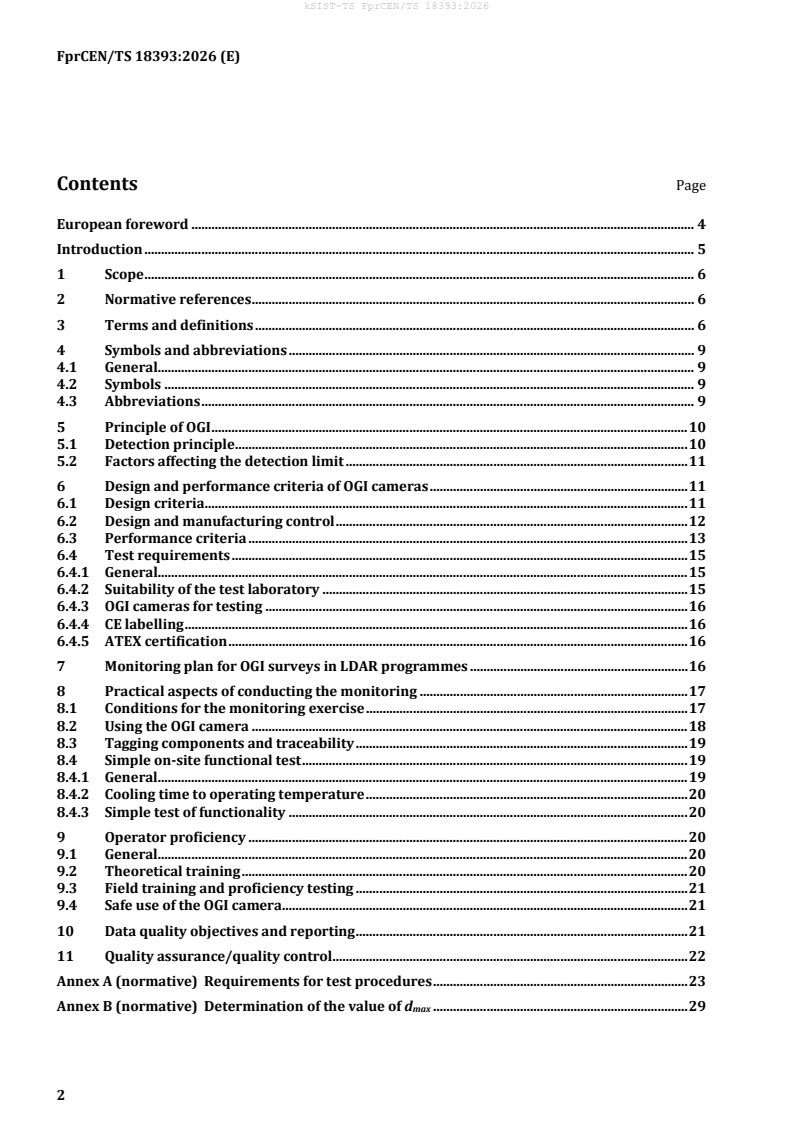
Contents Page
European foreword . 4
Introduction . 5
1 Scope . 6
2 Normative references . 6
3 Terms and definitions . 6
4 Symbols and abbreviations . 9
4.1 General. 9
4.2 Symbols . 9
4.3 Abbreviations . 9
5 Principle of OGI . 10
5.1 Detection principle . 10
5.2 Factors affecting the detection limit . 11
6 Design and performance criteria of OGI cameras . 11
6.1 Design criteria . 11
6.2 Design and manufacturing control . 12
6.3 Performance criteria . 13
6.4 Test requirements . 15
6.4.1 General. 15
6.4.2 Suitability of the test laboratory . 15
6.4.3 OGI cameras for testing . 16
6.4.4 CE labelling . 16
6.4.5 ATEX certification . 16
7 Monitoring plan for OGI surveys in LDAR programmes . 16
8 Practical aspects of conducting the monitoring . 17
8.1 Conditions for the monitoring exercise . 17
8.2 Using the OGI camera . 18
8.3 Tagging components and traceability . 19
8.4 Simple on-site functional test . 19
8.4.1 General. 19
8.4.2 Cooling time to operating temperature . 20
8.4.3 Simple test of functionality . 20
9 Operator proficiency . 20
9.1 General. 20
9.2 Theoretical training . 20
9.3 Field training and proficiency testing . 21
9.4 Safe use of the OGI camera . 21
10 Data quality objectives and reporting . 21
11 Quality assurance/quality control. 22
Annex A (normative) Requirements for test procedures . 23
Annex B (normative) Determination of the value of d . 29
max
Annex C (informative) Examples of inspection forms . 34
Annex D (normative) Competence of the personnel . 38
Annex E (informative) Quantitative Optical Gas Imaging . 40
Annex F (informative) Example of a d determination procedure . 42
max
Bibliography . 46
European foreword
This document (FprCEN/TS 18393:2026) has been prepared by Technical Committee CEN/TC 264 “Air
quality”, the secretariat of which is held by DIN.
This document is currently submitted to the Vote on TS.
Introduction
This document has been developed to provide detailed guidance on the use of optical gas imaging (OGI)
cameras for visualizing leaks of vapours and gases that can be detected using their spectral properties in
the infrared (IR) region of the electro-magnetic spectrum.
European legislation for a set of industrial activities states the operators of affected installations can put
in place a leak detection and repair (LDAR) programme to risk-assess, identify and either eliminate or
reduce fugitive and other diffuse emissions of certain vapours and gases that are harmful to human health
and the environment.
Under legislation, certain categories of industrial installations within the sectors for energy, waste
management, oil and gas refining, and the chemical sectors can have a LDAR programme. LDAR required
by legislation specifies the use of OGI cameras to detect leaks.
Although legislation does not currently prescribe OGI within LDAR programmes for other types of
industrial activity, the technique is still a powerful tool for visualizing leaks of gases and vapours with
have an IR absorption profile that OGI cameras can detect. These activities include but are not limited to:
small anaerobic digestion plants; landfill-gas infrastructure, and; natural-gas distribution systems.
OGI cameras have proven to be an effective detection technique, where an IR sensor is used to visualize
emissions of volatile organic compounds (VOCs), methane and other compounds (e.g. SF , NH ), which
6 3
cannot normally be seen by the human eye.
This document focuses on the use of OGI cameras dedicated to leak detection of VOCs, and methane. OGI
cameras can also be utilized for detecting other types of emissions, e.g. venting or non-fugitive diffuse
emissions. OGI cameras enable the user to visualize emissions – and make it possible to make a
comparative assessment between small, medium and large emissions. In addition to detection, some OGI
camera systems provide the means to quantify emission rates by implementing quantitative optical gas
imaging (QOGI). This document does not focus on QOGI but introduces the technique in an informative
annex.
The strength of an OGI camera is that it allows many components to be inspected in a relatively short
time, making this camera a powerful instrument for making fugitive emissions visible and then
controlling them. Although OGI cameras are highly portable and readily deployed and seem to be easy to
use, these devices require users to be trained and sufficiently experience to be proficient.
A typical deployment would use the OGI cameras to detect the larger leaks or as a complement of a
conventional LDAR programme by enabling screening of components inaccessible to point sampling
technique according to EN 15446, commonly known as “sniffing”, and applied to the framework
described in EN 17628.
This document does not describe techniques for quantifying releases of VOCs. This subject is covered by
EN 15446 for sniffing techniques, whilst forthcoming standards from CEN will describe other techniques
for quantifying VOCs emissions, such as bagging and QOGI.
1 Scope
This document specifies the performance requirements, test procedures, operator proficiency, and
operational requirements for a technique known as optical gas imaging (OGI).
This document applies to the use of OGI cameras as part of an LDAR programme. It specifies the scope of
application, performance requirements for OGI equipment and QA/QC procedures.
This document focuses on LDAR programmes, applied to VOCs (including methane), but a similar
approach could be applied to other compounds that have IR spectral properties that enable visualization,
by adapting the selection of OGI cameras having a detector with a different bandwidth.
Different types of technologies for OGI camera exist on the market, such as detectors which are either
cooled or uncooled, as well as active and passive OGI cameras. However, this document focuses on the
utilization of the most commonly utilized technology, the passive OGI cameras. Despite this, a similar
approach could be applied to the use of active OGI cameras.
2 Normative references
The following documents are referred to in the text in such a way that some or all of their content
constitutes requirements of this document. For dated references, only the edition cited applies. For
undated references, the latest edition of the referenced document (including any amendments) applies.
EN 17628:2022, Fugitive and diffuse emissions of common concern to industry sectors — Standard method
to determine diffuse emissions of volatile organic compounds into the atmosphere
EN 15446:2008, Fugitive and diffuse emissions of common concern to industry sectors — Measurement of
fugitive emission of vapours generating from equipment and piping leaks
3 Terms and definitions
For the purposes of this document, the following terms and definitions apply.
ISO and IEC maintain terminological databases for use in standardization at the following addresses:
• IEC Electropedia: available at https://www.electropedia.org/
• ISO Online browsing platform: available at https://www.iso.org/obp
3.1
active thermography
technique of applying an external energy source to an object or process, to induce a variation in
temperature for analysis with an IR camera
Note 1 to entry: Active thermography can be a viable non-destructive test method for objects or scenes with no
naturally occurring thermal variation. In other words, no naturally occurring temperature differences exist in the
object or scene.
Note 2 to entry: An active OGI camera uses a source of electromagnetic radiation to irradiate the background and
relies on a reflective surface in the background. The effect is to increase the sensitivity.
3.2
component
assembly or mechanical part of an equipment
Note 1 to entry: Examples are fitting, flange, pump seal, valve seal, open-ended line.
3.3
detection
recognition of the presence of an emission source in a certain area
3.4
detection limit
minimum quantity of a substance which produces an observable response. When using an OGI camera,
this limit is affected by environmental conditions. A theoretical detection limit can be observed and tested
under controlled conditions
3.5
diffuse emission
emission to the atmosphere from an identified site or facility, not specifically directed to identified stack
emission points
Note 1 to entry: This term comprises the sum of various unaccounted channelled emissions, fugitive emissions and
area emissions.
3.6
equipment
assembly composed by one or more components
Note 1 to entry: Examples are pump, manual valve, control valve, safety valve.
3.7
emission
discharge of substances into the atmosphere
Note 1 to entry: This term comprises four types of emission sources:
— Accounted channelled emissions (from monitored stacks)
— Unaccounted channelled emissions (from, e.g. vents, flares)
— Fugitive emissions (leaks from, e.g. valves seals)
— Other diffuse emissions (from, e.g. water treatment basins, coke storage)
3.8
fugitive emission
emission to the atmosphere caused by loss of tightness of an item which is designed to be tight
[SOURCE: EN 15446:2008 [9]]
3.9
localisation
determination with a certain degree of precision of the position of an emission
3.10
main equipment
identifiable asset with primary process function composed by one or more pieces of equipment,
frequently used as a top-level node in LDAR databases
Note 1 to entry: Examples are: compressors, distillation towers, individual basins, individual storage tanks, and
water separators.
3.11
maximal permitted distance of detection
greatest distance that can be practicably achieved on a day-to-day basis between a screened component
and the OGI system executing the survey (d )
max
Note 1 to entry: The maximum distance of detection is the greatest distance at which an emission source can be
detected under test conditions (see Annex A).
Note 2 to entry: The value of d is determined using the procedure described in Annex B. The value of d can be
max max
larger than the operating envelope determined in Annex A, depending on specific circumstances described in
Annex B.
3.12
noise equivalent concentration length
NECL
lowest detectable concentration of gas over a specified path length
Note 1 to entry: The unit is ppm∙m. A lower NECL in an OGI camera means a greater sensitivity for detecting gas
leaks
3.13
noise equivalent temperature difference
NETD
lowest temperature difference that an optical gas imaging camera can distinguish from the camera's
internal noise
Note 1 to entry: The unit is millikelvins (mK) and the lower the NETD, then the higher the sensitivity of the camera,
and hence a better image quality
3.14
operating envelope
range of conditions (i.e. wind speed, ΔT, viewing distance, OGI camera setup) within which a survey can
be conducted to achieve the quality objective
Note 1 to entry: Each OGI camera model has a unique operating envelope that depends on its intrinsic performance,
the lens fitted, the sensitivity mode, whether a tripod is used, and other parameters.
[SOURCE: Directive 2010/75/EC [3]]
3.15
passive thermography
relies upon the naturally occurring thermal radiation emitted from an object or process for condition
evaluations
Note 1 to entry: With passive thermography, thermal contrast is only observed with an IR camera if the target’s
temperature differs from the ambient temperature or surrounding objects. The resulting thermal image will show
little variation in colour or greyscale if there is no thermal contrast
Note 2 to entry: Passive OGI rely on favourable environmental conditions to detect a gas notably the value of ΔT (the
difference in temperature between the target gas and background).
3.16
quantification
determination of an emission rate
3.17
site
area within a defined perimeter where emissions might take place
3.18
volatile organic compound
VOC
organic compound, including methane, having a vapour pressure of 0,01 kPa or more at 293,15 K or
having the corresponding volatility under the conditions of use
[SOURCE: Directive 2010/75/EC [3], modified]
Note 1 to entry: Care is necessary in the use of the term VOC, as there are many different definitions in common
use. In some contexts, VOC excludes methane or methane and ethane. It is recommended to clearly state which
range of compounds is reported as VOC.
4 Symbols and abbreviations
4.1 General
For the purposes of this document, the following symbols and abbreviations apply.
4.2 Symbols
ΔT Difference in temperature between the target gas
and the background
d Maximal permitted distance of detection
max
d initial distance
ini
σ Standard deviation of the temporal noise
R Responsivity
V Average signal
T Temperature
4.3 Abbreviations
ATEX ATmosphères EXplosibles
CL Concentration Length
DL Detection limit
EPA Environmental Protection Agency
EUMR European Methane Regulation
GIS Geographic Information System
HSM High Sensitivity Mode
IR Infrared
LDAR Leak Detection and Repair
LEL Lower Explosive Limit
NECL Noise Equivalent Concentration Length
NETD Noise Equivalent Temperature Difference
OGI Optical Gas Imaging
PPE Personal Protective Equipment
QA/QC Quality Assurance/Quality Control
QOGI Quantitative Optical Gas Imaging
TVA Toxic Vapour Analyser
VOC Volatile Organic Compound
5 Principle of OGI
5.1 Detection principle
There are two types of OGI cameras, which are passive and active. A passive camera relies on imaging
infrared radiation absorption differences between the background and the targeted gas. An active OGI
camera uses a source to emit IR radiation on a given wavelength, to image its absorption by the targeted
gas. This technical specification focuses on passive OGI cameras.
NOTE This technical specification can be applied to active OGI cameras, with some adjustments to the procedures
and specifications.
Typically, OGI cameras operate in the IR region of the electromagnetic spectrum. An OGI camera system
consists of:
— a lens
— an optical filtering stage
— a detector
— software that processes the detector signal and
— an internal or external display to make the signals visible to the operator
The filter ensures that a narrow IR band passes through to the detector. This filter is selected such that
the IR wavelength of the target range of VOCs is detected by the camera. When the background radiation
is absorbed by the target gases, the gases are visible to the user of the camera.
Visibility of gases depends on four conditions:
— the target gas absorbs energy at the wavelength range that the filter allows to pass through to the
detector;
— the gases themselves are moving;
NOTE When the gas is moving, this creates a contrast between frames in the image, enabling the user to readily
see the gas.
— there is a difference between the temperature of the target gases and the background. This difference
is known as ΔT;
— the gas column density within the camera’s line of sight is sufficient to produce a detectable
radiometric contrast.
NOTE Column density is the product of gas concentration and optical path length through the plume. It is a key
factor for visibility. The most critical performance characteristic of an OGI camera is its detection limit (DL).
5.2 Factors affecting the detection limit
The DL will determine whether an OGI camera can detect fugitive emissions. Therefore, this document
specifies a minimum DL for cameras.
The factors which have the greatest influence on the DL are:
— ΔT
— camera design including:
o sensor type (cooled vs. uncooled, sensor pitch, lens, etc.)
o bandpass filter(s)
— the type of gas
— distance from the camera to the target gas
— complexity/uniformity of background
— dispersion conditions (wind, humidity, atmospheric stability, etc.)
— stability of the gas plume
day-to-day variations in field conditions, which in turn will affect the value of d
— max
NOTE 1 The maximal permitted distance of detection, dmax, is the greatest distance that can be practicably
achieved on a day-to-day basis.
NOTE 2 Many OGI cameras rely on frame-to-frame differences (e.g. high sensitivity mode (HSM), enhanced
mode…).
The capacity of an OGI camera to image a leak is linked to the ability of the operator of the OGI camera to
detect a contrasted emission plume onto the screen of the OGI camera. To achieve this objective, a
sufficient temperature contrast (i.e. the value of ΔT) between the plume and the background (i.e. what is
behind the emission plume) is necessary. Despite this, it should be noted that too great a value of ΔT could
also render the leak invisible. This can occur, for example, when the background consists of a very cold
or very hot pipeline, or a flare.
The filter of an OGI camera dedicated to detection of VOCs leaks is sensitive to water vapour. Therefore,
the water vapour cloud cannot be easily differentiated from the VOC leak cloud.
NOTE Only a multispectral camera can differentiate between a VOC emission plume and water vapour.
6 Design and performance criteria of OGI cameras
6.1 Design criteria
The OGI camera shall meet the following design criteria:
— The absorption range of IR radiation shall overlap with major absorption peak for species of interest;
For example, the presence of a narrowband filter adapted to the targeted VOCs;
NOTE Most of the VOCs have their IR absorption peak in the region of 3,3 µm, but some have a greater visibility
in the region of 10,5 µm (e.g. propylene, ethylene) or other narrow bands.
— to improve the detection of leaks the camera system shall have the means to enhance the
visualization in complex scenarios e.g. High Sensitivity Mode;
— the camera shall be designed for detecting gases and not be only a thermographic camera;
— the camera shall be capable of visualizing leaks of the targeted compounds in real time;
— the camera shall have the means to record images (for traceability purposes);
— the camera shall be equipped with a suitable detector to meet the requirements (cooled and uncooled
detectors exist);
— the camera shall be easy to transport and sufficiently portable, such that the camera operator is able
to carry and operate the camera without assistance;
In addition, it is strongly recommended that OGI cameras comply with ATEX requirements, although this
is not a mandatory requirement.
It is recommended that the camera meets the requirements to operate in at least Zone 2 and be certified
by an ATEX Notified Body. A camera certified for use in Zone 2 may be used in a Zone 1 area, if the
operator has a permit-to-work in Zone 1, with appropriate measures in place to comply with the
requirements of the ATEX Directive (2014/34/EU. The ATEX Directive specifies three zones based on the
risk of explosive atmospheres. These are:
— Zone 0 where an explosive atmosphere occurs for more than 1000 h per year (h/a);
— Zone 1 where explosive atmospheres occur for more than 10 h/a, but less than 1000 h/a;
— Zone 2 where explosive atmospheres occur for less than 10 h/a, yet still sufficiently probable such
that there is a need for controls over ignition sources
6.2 Design and manufacturing control
There shall be procedures for assessing the impact on the performance of the OGI camera, when making
design changes to the hardware, software and firmware of type-tested sensor systems. These procedures
are to ensure that if the manufacturer makes design changes, then the OGI camera still meets the
performance requirements and design criteria specified in this document.
In order to ensure manufacturing reproducibility and consistency, a technical file of design changes shall
be maintained for each type of OGI camera. The technical file shall include at least the following
information:
— component changes;
— dates of the changes;
— assessment of the impact of the changes, with respect to the applicable design requirements and
performance criteria;
— verifiable information and data supporting the assessment of the impact of the changes;
— assessment of the significant changes by the test laboratory;
— references to linked information, such as communications with a test laboratory.
When the manufacturer makes design changes, the test laboratory and any relevant body shall be
notified, unless the manufacturer has evidence to show that the OGI camera still meets the performance
stated in the original test report.
The following three classes of changes are defined in EN 15267-2 as:
— Type 0: changes that have no measurable influence on the performance of the OGI camera;
— Type 1: changes that can have an influence on the performance of the OGI camera, but where
subsequent tests prove that such changes do not have a significant influence;
— Type 2: changes that have a significant influence on the performance of the OGI camera.
A significant influence (Type 2) is considered to be one that reduces or improves the performance of the
OGI camera compared to that recorded in the original test report for the stipulated performance
characteristics.
OGI camera users shall be informed about such a type of change.
All changes to a type of OGI camera shall be evaluated. Where Type 2 changes are identified, the test
laboratory shall be consulted to confirm whether any additional testing is required to determine the
impact of any design changes. All changes and evaluations shall be documented in accordance with the
requirements of this document and in such a way that they can be audited.
To identify changes in hardware, firmware and software for the OGI camera, the version numbers shall
be made available to the user and test laboratory used for testing.
The hardware, firmware and software version numbers of the OGI cameras used for type testing shall
also be recorded in the test report.
The version number of the OGI camera manual supplied during type testing shall be recorded in the test
report.
These are minimum requirements and users should reference EN 15267-1 and EN 15267-2 for
regulatory purposes.
NOTE EN 15276-2 is a sector specific application of ISO 9001.
6.3 Performance criteria
OGI cameras shall meet the performance requirements corresponding to the type of survey for which
they are intended, as declared by the manufacturer and verified through type testing in accordance with
Annex A.
For surveys requiring detection of larger emissions (Performance Level 1), the camera shall be capable
of detecting and producing a visible image of the following gas releases under standard test conditions
(operating distance 2 m, ΔT ≤ 5 K, wind speed ≤ 1 m/s):
— methane at ≤ 17 g/h
— propane at ≤ 5 g/h
— butane at ≤ 5 g/h
For surveys requiring detection of smaller emissions (Performance Level 2), the camera shall additionally
be capable of detecting and producing a visible image of the following gas releases under the same
standard test conditions:
— methane at ≤ 1 g/h
— propane at ≤ 0.3 g/h
— butane at ≤ 0.3 g/h
NOTE 1 For applications under EU Regulation EU/2024/1787(EU Methane [RG2] Regulation (EUMR)), , the first
performance level corresponds to Type 1 LDAR surveys (repair threshold: 17 g/h methane) and the second
performance level corresponds to Type 2 LDAR surveys (repair threshold: 1 g/h methane).
NOTE 2 The equivalent flow rates for propane and butane are based on their typical response factor relative to
methane, which is based on the physical properties of gases and not the type of OGI camera.
OGI cameras used for LDAR programmes under the US EPA requirements have to be able to visualize a
gas mixture comprising half methane and half propane at a concentration of 10,000 ppm, at a flow rate
of ≤ 60g/hr from a orifice 0[RG3].635cm in diameter (operating distance 2 m, ΔT ≤ 5 K, wind
speed ≤ 1 m/s).
NOTE 3 This is an optional requirement for OGI camera manufacturers intending to supply the US market for
LDAR tasks, and other countries which apply the USEPA requirements.
There are two other performance characteristics that are not mandatory in this document but represent
best practice. These are the sensitivity characterized as a Noise Equivalent Temperature Difference
(NETD) and a detection limit expressed as a Noise Equivalent Concentration Length (NECL). If an OGI can
achieve an NETD of at least 25 mK and an NECL detection limit of 100 ppm·m for a ΔT of 5 K, then it is
highly likely that the OGI camera will exceed all the performance requirements.
NOTE 1 The German national standard VDI 4321 includes the above requirements for both NECL and NETD, and
the national standard NTA 8399 from the Netherlands includes the above requirement for NETD. Additionally,
ISO 18251-2 and IEC TS 63144-1 for thermographic cameras both include requirements and test procedures for
NETD.
NOTE 2 Annex A, which describes requirements for test procedures, also describes tests for NETD and NECL.
Table 1 summarizes the requirements of the four performance levels.
Table 1 — performance specifications
Performance Level 1, detection limits, individual gases Test procedures
Methane ≤ 17 g/h A.3.1
Propane ≤ 5 g/h A.3.1
Butane ≤ 5 g/h A.3.1
Performance Level 2, detection limits, individual gases
Methane ≤ 1 g/h A.3.1
Propane ≤ 0.3 g/h A.3.1
Butane ≤ 0.3 g/h A.3.1
Detection limit, gas mixture
Mixture consisting of 50 % methane, 50 % 10,000 ppm flow A.3.1
propane rate ≤ 60g/hr from
a 6.35mm orifice
NETD and NECL
NETD ≤ 25 mK A.3.2
NECL ≤ 100 ppm.m A.3.3
These are mandatory requirements in this document
These are optional, additional requirements in this document
6.4 Test requirements
6.4.1 General
All OGI camera models shall be tested in order to meet the design criteria specified in 6.1 and performance
criteria specified in 6.3. The test laboratories performing these tests shall perform the tests in a manner
which meets the requirements described in Annex A. General test requirements
All relevant tests shall be performed on two identical OGI cameras. Testing two identical cameras is
intended to assess the reproducibility of performance results across cameras of the same model. [RG4].
NOTE The test is performed in such a way that the material under analysis (measured component) is applied
to both visualization modes (normal mode and HSM) in the laboratory test and in the field test.
Changes in the environmental and test conditions shall not have a significant influence on the
performance characteristic tested. Therefore, all environmental and test conditions which have an
influence on the OGI camera shall be kept stable as far as practicable.
The environmental and test conditions shall be recorded during the tests. All test results shall be reported
at normal conditions.
NOTE: Normal environmental conditions are defined as a temperature of 293K ± 5 °, an atmospheric pressure of
1013 ± 50) kPa and a relative humidity of 50 % ± 30 %, non-condensing.
The test requirements specified in Annex A are the minimum requirements for testing procedures.
If a test requires several readings, the average of these readings shall be determined. If a test has to be
repeated (several test cycles), the averages of the individual test cycles shall be determined and meet the
applicable performance criteria.
The expanded uncertainty of the concentration of test gases at a confidence level of 95 % shall not exceed
3 %.
Tests do not have to be performed in the numerical order in this document, as the selection of tests and
their order depend on the characteristics and type of individual OGI camera.
It shall be documented whether the OGI camera meets the relevant performance criteria and all
environmental conditions pertaining during testing shall be recorded.
6.4.2 Suitability of the test laboratory
The testing shall be performed by e.g. an independent test laboratory and shall have appropriate
procedures for quality assurance and control.
NOTE 1 Applying EN ISO/IEC 17025 or an equivalent standard provide the means for demonstrating that the
test laboratory has appropriate procedures for quality assurance and quality control.
NOTE 2 A formal accreditation by a member body of the European Accreditation Organization to
EN ISO/IEC 17025 is a demonstration of conformity.
6.4.3 OGI cameras for testing
It shall be checked whether the two OGI cameras are complete and identical, by examining the
appropriate parts specified in the manufacturer’s documentation.
Diagrams and photographs shall be included of both OGI cameras in the test report, and copies of the
operating manual(s) for the OGI cameras.
6.4.4 CE labelling
If the OGI camera system is to comply with the requirements for CE labelling as specified in applicable EU
Directives, then the test laboratory shall be verify whether there is traceable evidence of compliance.
The requirements for CE labelling are specified in applicable EU Directives. These include, for example:
— Directive 2014/30/EU on the harmonization of the laws of the Member States relating to
electromagnetic compatibility, and
— Directive 2014/35/EU on the harmonization of the laws of the Member States relating to the making
available on the market of electrical equipment designed for use within certain voltage limits.
Verifiable and traceable evidence of compliance with the requirements of the relevant EU Directives
applicable to the equipment shall be applied.
6.4.5 ATEX certification
The status of the OGI camera’s certification shall be examined and reported in the test report.
7 Monitoring plan for OGI surveys in LDAR programmes
The objectives of the monitoring plan shall be determined and documented. The monitoring plan shall
include the following aspects:
— a generic risk assessment and review of site-specific risks;
— a description of what is to be monitored and the purpose of the monitoring;
— the nature of the location where monitoring will occur;
— the relevant operating conditions of the installation;
— ensure that a database or similar information with a summary of the potential sources of emission is
available. Record the progress of the measurements in it;
— ensure that means are available to record the time, the code of the emission source, film code, process
conditions, specifics, etc.
— ensure that means are available to measure and record meteorological conditions
— a procedure to ensure traceability, determining which operator uses the OGI camera for each location,
and which OGI camera is used;
— the components to be assessed;
— the VOCs to be controlled and the absorption area of the spectrum required;
— the envisaged period for monitoring;
— the requirements for the monitoring method;
— the relevance of any permit requirements;
— the competence of the personnel (see Annex D) using the OGI camera;
— choice of sensitivity capabilities, risk assessment, list of potentially leaking sources (database/map/
coordinates/description).
The detection plan shall also include:
— risk assessment, list of potentially leaking sources (database map/coordinates/
description);
— map of survey locations, LDAR database, leak documentation procedure needed;
— The survey shall consider the types of components where there are risks of leaks, including at least
the following geometries:
• closed-vent systems;
• pumps;
• compressors;
• pressure relief valves;
• valves;
• connectors;
• flanges;
• plugs;
• caps;
• open-ended lines.
8 Practical aspects of conducting the monitoring
8.1 Conditions for the monitoring exercise
Determine in advance under what conditions the monitoring will be feasible. The possible factors include:
— weather conditions
• air temperature
• wind speed
• precipitation
• fog
• cloud cover
• solar angle
— process conditions (e.g. operating pressure, storage temperature, tank movement (when
applicable))
8.2 Using the OGI camera
Before starting the measurements, ensure that:
— site safety requirements are complied with, including
— access to site information (e.g. operating conditions) is available;
— access to emergency contact details is available;
— personal safety equipment is available;
— a meter is available for detecting explosive atmospheres;
— the OGI camera operators are familiar with the local procedures for safety;
— information on locations is available, e.g. a map or local knowledge;
— the types of components that require monitoring with the OGI camera are specified (see Section 7)
— the OGI camera operator is proficient to perform the required tasks (see Annex D);
— the operators have performed a functional test of the OGI camera to check that the camera is working
properly (see Section 8.4);
— the OGI camera has sufficient memory and/or spare storage capacity to store the video recordings
and photographs from the leak survey;
— the OGI camera has sufficient battery capacity;
— the date and time settings of the OGI camera are correct.
— create the measurement plan;
— determining and recording the value of d according [RG6] to the procedure described in Annex B;
max
Only make OGI recordings of all emission sources if laid down specifically in the monitoring plan; the
basic principle is that an OGI recording will be made only if an emission is detected.
Before accessing the monitoring zone, first perform a safety scan from a safe distance for very large and
potentially hazardous leaks. If there are no such leaks, continue with the following steps.
NOTE 1 A safe distance usually corresponds to watching the targeted area from a reputed ATEX free zone. e.g.
initial check of an ATEX zone 1 from an ATEX zone 2.
— perform an accurate and systematic round of monitoring based on the measuring plan, while
preventing exposure to released VOC emissions as much as possible;
— record [RG7] a continuously emitting source for at least 10 seconds (per recording mode and filming
position)
— record a fluctuating emission source for at least 10 s or for as much longer as is necessary to make
its fluctuating character visible (per recording mode and filming position);
— if possible, film around the emitting source;
— it is recommended to make a visible light recording (non-IR) of the emission source. The visual
recording of the source should also include the surroundings of the leaking source to aid the
interpretation of the video.
NOTE 2 A visible light recording of the emitting source can be a pho
...