

prEN IEC 63409-6:2026
(Main)Photovoltaic power generating systems connection with the grid - Testing of power conversion equipment - Part 6: Power control functions and grid support
- Status
- Not Published
- Publication Date
- 22-Nov-2027
- Technical Committee
- CLC/TC 82 - Solar photovoltaic energy systems
- Drafting Committee
- IEC/TC 82 - IEC_TC_82
- Current Stage
- 4098 - Decision to drop project - Standstill maintained / released - Enquiry
- Start Date
- 17-Aug-2026
- Completion Date
- 25-Aug-2026

prEN IEC 63409-6:2026 is a draft CLC/IEC document for photovoltaic power generating systems connected to the grid. It specifies test procedures for power conversion equipment (PCE) used in photovoltaic (PV) systems, with or without energy storage, to check power control functions and grid support behavior. It is aimed at manufacturers, test laboratories, and conformity assessment teams that need to verify how a PCE follows setpoints and reacts to grid changes.
What does prEN IEC 63409-6:2026 specify?
prEN IEC 63409-6:2026 specifies how to test the performance of power control functions in PCE for PV systems. Its focus is on test methods, measurement setup, and pass criteria based on the manufacturer’s declared tolerances.
The document is organized around general requirements in Clause 4, test procedures in Clause 5, and supporting annexes. Clause 5 covers both constant power control and response control against grid variation.
| Annex | What it covers |
|---|---|
| Annex A | Examples of testing environments, including power supply and measuring instrument specifications |
| Annex B | Normative sign conventions for voltage, current, active power, and reactive power measurements |
| Annex C | Influence of MPPT control and PV simulator behavior on test results |
| Annex D | Grid support functions in other standards, with chapter lists and abstracts |
What are the key requirements of prEN IEC 63409-6:2026?
General test conditions
Clause 4 sets the basic test conditions that make results comparable. prEN IEC 63409-6:2026 allows tests to be performed in any order unless the document says otherwise, and the same sample does not have to be used for every test.
Clause 4.1.4 says all grid support functions except the one under test should be disabled. If another function must stay enabled to complete the test, the report has to note that fact. In practice, this helps isolate the behavior being checked and avoids ambiguous results.
Clause 4.2 requires the DC and AC ports of the EUT (equipment under test) to be connected to external supplies according to the manufacturer’s instructions. The document also requires measurement of apparent power, active power, and reactive power at the AC ports, using the sign conventions in Annex B. That matters because a reversed measurement direction changes the meaning of the result.
Clause 4.3 ties the tests to IEC 61850-7-4 and IEC 61850-7-420 logical nodes and data objects. The manufacturer has to declare the monitored parameters before testing, and the document lists status and measured values in Tables 1 and 2. This gives labs a common parameter map for setting and reading the PCE.
Constant power control
Clause 5.2 covers constant power control. It includes active power control, change of maximum active power configuration, and reactive power control in constant reactive power mode and constant power factor mode.
For active power control and maximum active power control, the test checks whether the output follows the commanded setpoint. The criterion is the error between the PCE setting and the measured value at the AC ports, within the allowable range declared by the manufacturer. In practice, this tells a buyer or certifier whether the unit can hold a commanded power limit accurately.
For constant reactive power control, the same approach applies to reactive power. Clause 5.2.4.1 uses the reactive power setpoint and compares it with the measured value at the AC ports, again against the manufacturer’s declared tolerance.
For constant power factor control, the document checks accuracy at the commanded power factor and also measures active power, reactive power, and power factor during changes. This matters for grid codes that require a specific displacement power factor over a range of operating points.
Response control against grid variation
Clause 5.3 covers response control functions that change output when frequency or voltage changes. The functions include frequency-watt control, voltage-watt control, voltage-var control, and power-reactive power/power factor control.
Clause 5.3.2 defines common procedures for frequency-watt, voltage-watt, and voltage-var testing. The tests use step changes in the independent variable, measure voltage, current, active power, apparent power, reactive power, and power factor, and record settling time. The tests are repeated at different output levels, including 100%, 66%, and 33% of rated active power. That shows whether the response is consistent across operating points.
Clause 5.3.2.3 bases acceptance on the manufacturer’s declared permissible range for the stabilized output and the settling time. In practice, the document does not impose one universal performance limit here; it requires the declared performance to be verified.
Clause 5.3.3 gives separate procedures for each response function using configured curves and parameters in Tables 10 to 19. The tests check curve behavior, ramp-rate limiting, settling time settings, and snapshot behavior where used. For example, the voltage-var, frequency-watt, voltage-watt, power-reactive power, and power factor functions are each tested against their configured characteristic curves.
Annex C is relevant to these tests because it explains that MPPT control and the choice of DC source can change transient-response results. For a lab, this means the DC supply type has to be recorded, and the test setup should avoid DC-side effects that distort the AC response.
What terms does prEN IEC 63409-6:2026 define?
- battery energy storage system (BESS) - An electrical energy storage system based on batteries with secondary cells, including flow battery energy systems.
- power conversion equipment (PCE) - An electrical device that converts one kind of electrical power into another with respect to voltage, current, and frequency.
- step response time - The time from an input step change until the output first reaches a specified percentage of the final change.
- settling time - The time from an input step change until the output stays within the specified tolerance band around steady state.
- overshoot - The maximum transient deviation of the output from its final steady-state value.
- dead time - The time interval by which the output is shifted relative to the input.
Who uses prEN IEC 63409-6:2026?
Manufacturers of PCE for PV systems use prEN IEC 63409-6:2026 to design validation and factory or type testing for control functions. Test laboratories use it to set up AC and DC supplies, measurement points, and pass/fail checks in a repeatable way.
Conformity assessment teams use it to check whether a PCE follows commanded active power, reactive power, and power factor settings, and whether it responds correctly to grid frequency or voltage changes. Grid-connection engineers and technical buyers use it when they need evidence that a PV inverter or similar PCE supports the required control modes.
The document is also relevant where PV systems include energy storage, because the procedures cover PCE with or without BESS and include cases where active power flow can be absorbing as well as generating.
What changed in prEN IEC 63409-6:2026 from the previous edition?
prEN IEC 63409-6:2026 supersedes IEC committee draft documents 82/2412/CD and 82/2458A/CC.
Which standards are used with prEN IEC 63409-6:2026?
- IEC 60050-351:2013 - Provides control-technology terminology used for response time, settling time, overshoot, and dead time.
- IEC TS 62786-1:2023 - Provides the general DER grid-connection requirements that the test items are aligned with.
- IEC TS 61836 - Provides solar photovoltaic energy system terms, definitions, and symbols.
- IEC 62934:2021 - Provides renewable-energy grid-integration terms and definitions.
- IEC 61850-7-4:2010/AMD1:2020 - Provides the basic communication structure, logical node classes, and data object classes used for parameter setting and monitoring.
- IEC 61850-7-420:2021 - Provides DER and distribution automation logical nodes and data objects used in the test procedures.
What does the prEN IEC 63409-6:2026 document contain?
The document contains step-by-step test procedures, parameter tables, and acceptance criteria for each control function. It also includes example figures for step response and test setup, plus curve-based procedures for voltage-var, frequency-watt, voltage-watt, power-reactive power, and power factor control.
Annex A gives example test environments and recommended capabilities for AC and DC power supplies and measuring instruments. Annex B explains the sign conventions and power-flow meanings needed to interpret measured voltage, current, active power, and reactive power correctly.
Annex C explains how PV simulator behavior and MPPT control can change transient results, which is important when comparing tests across labs. Annex D compares the grid support functions in this document with related functions in IEEE 1547-1, EN 50549-10, and AS/NZS 4777.2.
Frequently Asked Questions
prEN IEC 63409-6:2026 is a draft published by CLC. Its full title is "Photovoltaic power generating systems connection with the grid - Testing of power conversion equipment - Part 6: Power control functions and grid support". This standard covers: Photovoltaic power generating systems connection with the grid - Testing of power conversion equipment - Part 6: Power control functions and grid support
Photovoltaic power generating systems connection with the grid - Testing of power conversion equipment - Part 6: Power control functions and grid support
prEN IEC 63409-6:2026 is available in PDF format for immediate download after purchase. The document can be added to your cart and obtained through the secure checkout process. Digital delivery ensures instant access to the complete standard document.
Standards Content (Sample)
SLOVENSKI STANDARD
01-september-2026
Povezava fotonapetostnih sistemov za proizvodnjo električne energije z omrežjem
- Preskušanje opreme za pretvorbo električne energije - 6. del: Funkcije za nadzor
moči in podpora omrežju
Photovoltaic power generating systems connection with the grid - Testing of power
conversion equipment - Part 6: Power control functions and grid support
Photovoltaische Stromerzeugungssysteme mit Netzanschluss - Konformitätsbewertung
für Leistungswandler - Teil 6: Leistungsregelungsfunktionen und Netzunterstützung
Ta slovenski standard je istoveten z: prEN IEC 63409-6:2026
ICS:
27.160 Sončna energija Solar energy engineering
29.240.01 Omrežja za prenos in Power transmission and
distribucijo električne energije distribution networks in
na splošno general
2003-01.Slovenski inštitut za standardizacijo. Razmnoževanje celote ali delov tega standarda ni dovoljeno.
82/2589/CDV
COMMITTEE DRAFT FOR VOTE (CDV)
PROJECT NUMBER:
IEC 63409-6 ED1
DATE OF CIRCULATION: CLOSING DATE FOR VOTING:
2026-05-01 2026-07-24
SUPERSEDES DOCUMENTS:
82/2412/CD, 82/2458A/CC
IEC TC 82 : SOLAR PHOTOVOLTAIC ENERGY SYSTEMS
SECRETARIAT: SECRETARY:
United States of America Mr George Kelly
OF INTEREST TO THE FOLLOWING COMMITTEES: HORIZONTAL FUNCTION(S):
TC 8,TC 22,TC 57,TC 69,TC 77,SC 77A,TC 88,TC
120,ACTAD
ASPECTS CONCERNED:
SUBMITTED FOR CENELEC PARALLEL VOTING NOT SUBMITTED FOR CENELEC PARALLEL VOTING
Attention IEC-CENELEC parallel voting
The attention of IEC National Committees, members of
CENELEC, is drawn to the fact that this Committee Draft
for Vote (CDV) is submitted for parallel voting.
The CENELEC members are invited to vote through the
CENELEC online voting system.
This document is still under study and subject to change. It should not be used for reference purposes.
Recipients of this document are invited to submit, with their comments, notification of any relevant patent rights of
which they are aware and to provide supporting documentation.
Recipients of this document are invited to submit, with their comments, notification of any relevant “In Some
Countries” clauses to be included should this proposal proceed. Recipients are reminded that the CDV stage is
the final stage for submitting ISC clauses. (SEE AC/22/2007 OR NEW GUIDANCE DOC).
TITLE:
Photovoltaic power generating systems connection with the grid - Testing of power
conversion equipment- Part 6: Power control functions and grid support
PROPOSED STABILITY DATE: 2032
NOTE FROM TC/SC OFFICERS:
This project was discussed and supported by WG6 during their meeting in 2025-10.
electronic file, to make a copy and to print out the content for the sole purpose of preparing National Committee positions.
You may not copy or "mirror" the file or printed version of the document, or any part of it, for any other purpose without
permission in writing from IEC.
IEC CDV 63409-6 © IEC 2026
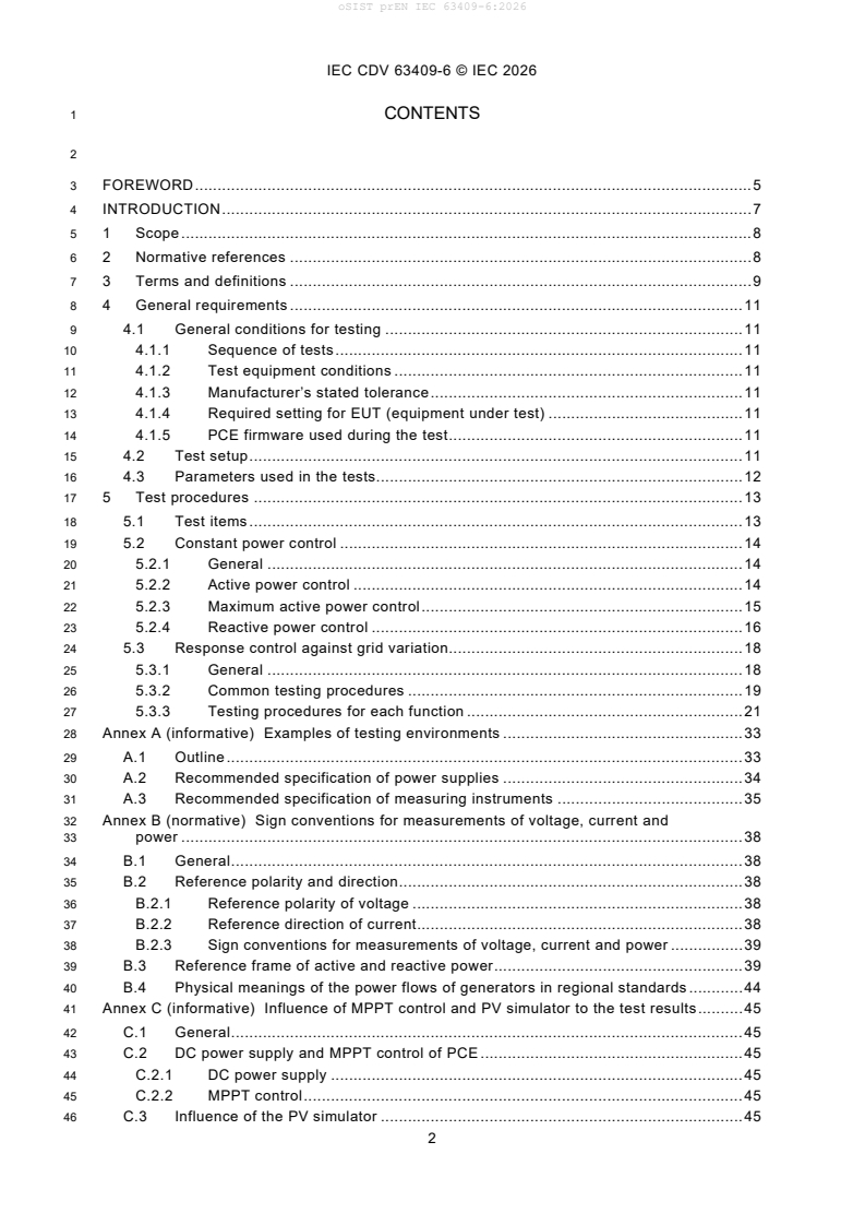
1 CONTENTS
3 FOREWORD . 5
4 INTRODUCTION . 7
5 1 Scope . 8
6 2 Normative references . 8
7 3 Terms and definitions . 9
8 4 General requirements . 11
9 4.1 General conditions for testing . 11
10 4.1.1 Sequence of tests . 11
11 4.1.2 Test equipment conditions . 11
12 4.1.3 Manufacturer’s stated tolerance . 11
13 4.1.4 Required setting for EUT (equipment under test) . 11
14 4.1.5 PCE firmware used during the test . 11
15 4.2 Test setup . 11
16 4.3 Parameters used in the tests. 12
17 5 Test procedures . 13
18 5.1 Test items . 13
19 5.2 Constant power control . 14
20 5.2.1 General . 14
21 5.2.2 Active power control . 14
22 5.2.3 Maximum active power control . 15
23 5.2.4 Reactive power control . 16
24 5.3 Response control against grid variation. 18
25 5.3.1 General . 18
26 5.3.2 Common testing procedures . 19
27 5.3.3 Testing procedures for each function . 21
28 Annex A (informative) Examples of testing environments . 33
29 A.1 Outline . 33
30 A.2 Recommended specification of power supplies . 34
31 A.3 Recommended specification of measuring instruments . 35
32 Annex B (normative) Sign conventions for measurements of voltage, current and
33 power . 38
34 B.1 General . 38
35 B.2 Reference polarity and direction . 38
36 B.2.1 Reference polarity of voltage . 38
37 B.2.2 Reference direction of current . 38
38 B.2.3 Sign conventions for measurements of voltage, current and power . 39
39 B.3 Reference frame of active and reactive power . 39
40 B.4 Physical meanings of the power flows of generators in regional standards . 44
41 Annex C (informative) Influence of MPPT control and PV simulator to the test results . 45
42 C.1 General . 45
43 C.2 DC power supply and MPPT control of PCE . 45
44 C.2.1 DC power supply . 45
45 C.2.2 MPPT control . 45
46 C.3 Influence of the PV simulator . 45
IEC CDV 63409-6 © IEC 2026
47 Annex D (informative) Grid support functions in other standards . 48
48 D.1 General . 48
49 D.2 Chapter list of grid support functions . 48
50 D.3 Abstract of grid support functions . 49
51 Bibliography . 55
53 Figure 1 – Overview of IEC 63409 series . 7
54 Figure 2 – Example of step response . 11
55 Figure 3 – Example of a test setup . 12
56 Figure 4 –Characteristic curve set in the EUT for active power response control . 20
57 Figure 5 –Characteristic curve set in the EUT for reactive power response control . 20
58 Figure 6 – Profile for response control test . 21
59 Figure A.1 – Example of a testing environment . 33
60 Figure B.1 – Reference polarity of voltage . 38
61 Figure B.2 – Reference polarity of current . 38
62 Figure B.3 – Reference polarity and direction for the measurements for DER . 39
63 Figure B.4 – Reference polarity and direction for the measurements for load . 39
64 Figure B.5 – Rotating vector voltage and current for load . 40
65 Figure B.6 – Rotating vector voltage and current for DER . 40
66 Figure B.7 – Complex power for load . 42
67 Figure B.8 – Complex power for DER . 42
68 Figure B.9 – Power quadrants for load . 43
69 Figure B.10 – Power quadrants for DER . 43
70 Figure C.1 – PV simulator characteristics examples . 45
71 Figure C.2 – Active power control test waveform with constant DC voltage source and
72 no MPPT . 46
73 Figure C.3 – Active power control test waveform with PV simulator and MPPT enabled . 46
74 Figure C.4 – Examples of operational point movement of a PCE during Active power
75 control tests . 47
77 Table 1 – Status of PCE . 12
78 Table 2 – Measured values of PCE . 12
79 Table 3 – Test items and relations to IEC TS 62786-1 and information models . 14
80 Table 4 – Minimum required parameters for active power control . 14
81 Table 5 – Minimum required parameters for maximum active power control . 16
82 Table 6 – Minimum required parameters for reactive power control . 16
83 Table 7 – Minimum required parameters for constant power factor control . 17
84 Table 8 – Test parameter for response control . 19
85 Table 9 – Frequency / voltage points for test. 21
86 Table 10 – Minimum required parameters for Voltage – Var control . 22
87 Table 11 – Testing procedures for Voltage – Var control . 22
88 Table 12 – Minimum required parameters for Frequency – Watt control . 24
89 Table 13 – Testing procedures for Frequency – Watt control . 24
90 Table 14 – Minimum required parameters for Voltage – Watt control . 26
IEC CDV 63409-6 © IEC 2026
91 Table 15 – Testing procedures for Voltage – Watt control . 27
92 Table 16 – Minimum required parameters for Power - reactive power control . 28
93 Table 17 – Testing procedures for Power – Reactive power control . 29
94 Table 18 – Minimum required parameters for Power - power factor control . 30
95 Table 19 – Testing procedures for Power - power factor control . 31
96 Table A.1 – Required functions for power supplies . 33
97 Table A.2 – Electrical quantity measured with measuring instruments or devices . 34
98 Table A.3 – Recommended specifications for power supplies . 35
99 Table A.4 – Recommended specifications of power quality measurement . 36
100 Table A.5 – Recommended specifications of waveform monitoring and recording
101 device . 36
102 Table B.1 – Physical meanings of the power flows of loads . 43
103 Table B.2 – Physical meanings of the power flows of generators . 44
104 Table B.3 – Physical meanings of the power flows of generators in Japan . 44
105 Table B.4 – Physical meanings of the power flows of generators in IEEE 1547.1 . 44
106 Table B.5 – Physical meanings of the power flows of generators in EN 50549-10 . 44
107 Table B.6 – Physical meanings of the power flows of generators in AS/NZS 4777.2 . 44
108 Table D.1 – Chapter list of grid support functions in other standards . 48
109 Table D.2 – Abstract of grid support functions in IEEE 1547-1 . 49
110 Table D.3 – Abstract of grid supports function in EN 50549-10. 51
111 Table D.4 – Abstract of grid support function in AS/NZS 4777.2 . 52
IEC CDV 63409-6 © IEC 2026
115 INTERNATIONAL ELECTROTECHNICAL COMMISSION
116 ____________
118 PHOTOVOLTAIC POWER GENERATING SYSTEMS
119 CONNECTION WITH THE GRID – TESTING OF
120 POWER CONVERSION EQUIPMENT
122 Part 6: Power control functions and grid support
125 FOREWORD
126 1) The International Electrotechnical Commission (IEC) is a worldwide organization for standardization comprising
127 all national electrotechnical committees (IEC National Committees). The object of IEC is to promote international
128 co-operation on all questions concerning standardization in the electrical and electronic fields. To this end and
129 in addition to other activities, IEC publishes International Standards, Technical Specifications, Technical Reports,
130 Publicly Available Specifications (PAS) and Guides (hereafter referred to as "IEC Publication(s)"). Their
131 preparation is entrusted to technical committees; any IEC National Committee interested in the subject dealt with
132 may participate in this preparatory work. International, governmental and non-governmental organizations liaising
133 with the IEC also participate in this preparation. IEC collaborates closely with the International Organization for
134 Standardization (ISO) in accordance with conditions determined by agreement between the two organizations.
135 2) The formal decisions or agreements of IEC on technical matters express, as nearly as possible, an international
136 consensus of opinion on the relevant subjects since each technical committee has representation from all
137 interested IEC National Committees.
138 3) IEC Publications have the form of recommendations for international use and are accepted by IEC National
139 Committees in that sense. While all reasonable efforts are made to ensure that the technical content of IEC
140 Publications is accurate, IEC cannot be held responsible for the way in which they are used or for any
141 misinterpretation by any end user.
142 4) In order to promote international uniformity, IEC National Committees undertake to apply IEC Publications
143 transparently to the maximum extent possible in their national and regional publications. Any divergence between
144 any IEC Publication and the corresponding national or regional publication shall be clearly indicated in the latter.
145 5) IEC itself does not provide any attestation of conformity. Independent certification bodies provide conformity
146 assessment services and, in some areas, access to IEC marks of conformity. IEC is not responsible for any
147 services carried out by independent certification bodies.
148 6) All users should ensure that they have the latest edition of this publication.
149 7) No liability shall attach to IEC or its directors, employees, servants or agents including individual experts and
150 members of its technical committees and IEC National Committees for any personal injury, property damage or
151 other damage of any nature whatsoever, whether direct or indirect, or for costs (including legal fees) and
152 expenses arising out of the publication, use of, or reliance upon, this IEC Publication or any other IEC
153 Publications.
154 8) Attention is drawn to the Normative references cited in this publication. Use of the referenced publications is
155 indispensable for the correct application of this publication.
156 9) IEC draws attention to the possibility that the implementation of this document may involve the use of (a)
157 patent(s). IEC takes no position concerning the evidence, validity or applicability of any claimed patent rights in
158 respect thereof. As of the date of publication of this document, IEC had not received notice of (a) patent(s), which
159 may be required to implement this document. However, implementers are cautioned that this may not represent
160 the latest information, which may be obtained from the patent database available at https://patents.iec.ch. IEC
161 shall not be held responsible for identifying any or all such patent rights.
162 IEC 63409-6 has been prepared by the working group 6: Balance-of-system components, of
163 IEC technical committee 82: Solar photovoltaic energy systems. It is an International Standard.
164 The text of this International standard is based on the following documents:
Draft Report on voting
XX/XX/FDIS XX/XX/RVD
166 Full information on the voting for its approval can be found in the report on voting indicated in
167 the above table.
IEC CDV 63409-6 © IEC 2026
168 The language used for the development of this International Standard is English.
169 This document was drafted in accordance with ISO/IEC Directives, Part 2, and developed in
170 accordance with ISO/IEC Directives, Part 1 and ISO/IEC Directives, IEC Supplement, available
171 at www.iec.ch/members_experts/refdocs. The main document types developed by IEC are
172 described in greater detail at www.iec.ch/publications.
173 The committee has decided that the contents of this document will remain unchanged until the
174 stability date indicated on the IEC website under webstore.iec.ch in the data related to the
175 specific document. At this date, the document will be
176 • reconfirmed,
177 • withdrawn,
178 • replaced by a revised edition, or
179 • amended.
IEC CDV 63409-6 © IEC 2026
INTRODUCTION
Background
TC82 has been making efforts to contribute to the standardization of DER connection with the grid. In
2016, TC82 joined TC8/JWG10 to standardize utility power system operation requirements. In parallel
with this liaison work, TC82 has also been preparing the standardization of testing of grid connection
requirements for power conversion equipment (PCE) for use in PV systems since 2016.
Purpose
This document proposes Part 6 of this series which gives test procedures for confirming power control
functions and grid support of PCE.
Figure 1 gives an overview of the structure of the whole IEC 63409 series.
Figure 1 – Overview of IEC 63409 series
IEC CDV 63409-6 © IEC 2026
PHOTOVOLTAIC POWER GENERATING SYSTEMS
CONNECTION WITH THE GRID – TESTING OF
POWER CONVERSION EQUIPMENT
PART 6: POWER CONTROL FUNCTIONS AND GRID SUPPORT
1 Scope
This part of IEC 63409 specifies test procedures for the evaluation of performance of power
control functions of power conversion equipment (PCE) for use in photovoltaic (PV) power
systems with or without energy storage. This document covers testing requirements of the
following functions equipped with the PCE:
• Constant power control
– Active power control
– Change of maximum active power configuration
– Reactive power control (constant reactive power control, constant power factor control)
• Response control
– Active power response to frequency variations (frequency - watt control)
– Active power response to voltage variations (voltage - watt control)
– Reactive power response to voltage variations (voltage - var control)
– Power - reactive power / power factor control
2 Normative references
The following documents are referred to in the text in such a way that some or all of their content
constitutes requirements of this document. For dated references, only the edition cited applies.
For undated references, the latest edition of the referenced document (including any
amendments) applies.
IEC 60050-351:2013, International Electrotechnical Vocabulary (IEV) - Part 901: Control
technology
IEC TS 62786-1:2023, Distributed energy resources connection with the grid – Part 1: General
requirements
IEC TS 61836, Solar photovoltaic energy systems - Terms, definitions and symbols
IEC 62934:2021, Grid integration of renewable energy generation - Terms and definitions
IEC 61850-7-4:2010/AMD1:2020, Amendment 1 - Communication networks and systems for
power utility automation - Part 7-4: Basic communication structure - Compatible logical node
classes and data object classes
IEC 61850-7-420:2021, Communication networks and systems for power utility automation -
Part 7-420: Basic communication structure - Distributed energy resources and distribution
automation logical nodes
IEC CDV 63409-6 © IEC 2026
3 Terms and definitions
For the purposes of this document, the terms and definitions given in IEC TS 61836, IEC 62934,
IEC TS 62786 series, and the following apply.
ISO and IEC maintain terminology databases for use in standardization at the following
addresses:
• IEC Electropedia: available at https://www.electropedia.org/
• ISO Online browsing platform: available at https://www.iso.org/obp
3.1
battery energy storage system
BESS
electrical energy storage system with an accumulation subsystem based on batteries with
secondary cells
Note 1 to entry: Battery energy storage systems include flow battery energy systems.
[SOURCE: IEC 60050-631:2024]
3.2
power conversion equipment
PCE
electrical device converting one kind of electrical power from a voltage or current source into
another kind of electrical power with respect to voltage, current and frequency
[SOURCE: IEC 62109-1:2010, 3.66]
3.3
step response time
for a step response the duration of the time interval between the instant of the step change of
an input variable and the instant when the output variable reaches for the first time a specified
percentage of the difference between the final and the initial steady-state value
Note: See Figure 2
[SOURCE: IEC 60050-351:2013, 351-45-36]
3.4
settling time
for a step response the duration of the time interval between the instant of the step change of
an input variable and the instant, when the difference between the step response and their
steady-state value remains smaller than the transient value tolerance
Note: See Figure 2
[SOURCE: IEC 60050-351:2013, 351-45-37]
3.5
overshoot
for a step response of a transfer element the maximum transient deviation from the final
steady-state value of the output variable, usually expressed in percent of the difference
between the final and the initial steady-state values and for reference-variable step response
or disturbance-variable step response of a control system the maximum transient deviation
from the desired value
Note: See Figure 2
IEC CDV 63409-6 © IEC 2026
[SOURCE: IEC 60050-351:2013, 351-45-37]
3.6
dead time
in a dead-time element the duration of the time interval by which the output variable is shifted
relative to the input variable
Note: See Figure 2
[SOURCE: IEC 60050-351:2013, 351-50-30]
3.7
tolerance band
tolerance limit
with stabilized power supplies the range of steady-state values of a stabilized output quantity
lying between specified limits of deviation from a preset value, e.g. a nominal value
Note: See Figure 2
[SOURCE: IEC 60050-551:1998, 551-19-07]
Key
1) For periodic behaviour
2) For aperiodic behaviour
u Input variable
U Initial value of the input variable
U Step height of the input variable
s
v Output variable
V , V Steady-state values before and after application of the step
0 ∞
IEC CDV 63409-6 © IEC 2026
v
Overshoot (maximum transient deviation from the final steady-state value)
m
2・Δv Tolerance band
s
T
Step response time
sr
T Settling time
s
T Dead time
t
[SOURCE: IEC 60050-351: 2013, 351-45-36]
Figure 2 – Example of step response
4 General requirements
4.1 General conditions for testing
4.1.1 Sequence of tests
The test may be performed in any order unless otherwise specified in this document. It is not
necessary to use the same sample for all tests unless otherwise specified in this document.
4.1.2 Test equipment conditions
Examples of the test equipment such as external power supplies and test instruments are
described in Annex A.
4.1.3 Manufacturer’s stated tolerance
The tolerance bands for ac voltage, frequency, active power, reactive power and the time
measurements can be subject to local regulations. If not, the manufacturer of the PCE under
evaluation shall state the tolerance.
4.1.4 Required setting for EUT (equipment under test)
All the grid support functions, except being tested function, should be disabled throughout the
test. If any one of the grid support functions is essential to perform the test, it is permissible to
enable it. In that case, it shall be written in the test report as remark that the specific function
was enabled during the test because it was essential to complete the test.
Maximum power point tracking (MPPT) and DC power supply shall be configured as written in
4.2.
4.1.5 PCE firmware used during the test
The versions of the PCE firmware used during the test shall be recorded in the test report.
4.2 Test setup
During testing, the EUT’s DC and AC ports shall be connected to external DC and AC power
supplies according to EUT manufacturer’s instructions. The test circuit diagram with positions
of measurement sensors shall be recorded in the test report. Figure 3 shows the typical test
setup required for test items described in this document.
Apparent power, active power and reactive power shall be measured at AC ports of EUT. The
current measuring instruments at AC port of the EUT shall be installed so that the current
flowing from EUT to AC power supply is measured as positive. See Annex B or more detailed
definitions of sign conventions for measurements of voltage, current and power in this document.
IEC CDV 63409-6 © IEC 2026
The testing of the EUT shall not be influenced by the performance of DC power supply used for
the test. Therefore, where the EUT has the capability to disable MPPT control, it is allowed to
do so and a DC power supply that is able to provide constant voltage at any required power
levels shall be used. A PV simulator may be used provided that the test results are not
influenced by any DC instability by the PV simulator. In each case, remarks shall be written in
the test report to note the type of the DC power supply or PV simulator used in the test. See
Annex C for supplemental information regarding the influences from the PV simulator.
Figure 3 – Example of a test setup
4.3 Parameters used in the tests
This document describes the parameter setting procedure using the Logical node (LN) and Data
object (message parameter) written in IEC 61850-7-4, and IEC 61850-7-420.
The tests described in this document require parameter setting changes and status monitoring,
but it does not matter whether remote communications are used to change or monitor the
parameters. It does not mean that information exchange or remote monitoring with logical nodes
specified in IEC 61850 shall be applied to evaluate the performance of functions. Date objects,
or parameters, are used to describe test procedures.
The monitoring parameters for status of PCE are shown in Table 1, and measured value of PCE
are shown in Table 2. Manufacturer shall declare the parameters before starting the tests.
Table 1 – Status of PCE
IEC 61850
Item
Standard LN message parameter Description
CSWI Pos.stVal Circuit breaker / switch
Switch controller IEC 61850-7-4
position
Table 2 – Measured values of PCE
IEC 61850
Item
Standard LN message parameter Description
AC voltage MMXU PPV.phsAB / "PPV: Phase to Phase
PNV.phsA Voltage
PNV: Phase to Neutral
Voltage"
IEC 61850-7-4
PPV.phsBC / "PPV: Phase to Phase
PNV.phsB Voltage
PNV: Phase to Neutral
Voltage"
IEC CDV 63409-6 © IEC 2026
PPV.phsCA / "PPV: Phase to Phase
PNV.phsC Voltage
PNV: Phase to Neutral
Voltage"
AC current A.phsA phase current
A.phsB phase current
A.phsC phase current
Apparent power TotVA The total apparent power
in a three-phase circuit
[VA].
VA.phsA Phase A apparent power
VA.phsB Phase B apparent power
VA.phsC Phase C apparent power
Active power TotW The total Active power in
a three-phase circuit
[W].
W.phsA Phase A active power
W.phsB Phase B active power
W.phsC Phase C active power
Reactive power TotVAr The total Reactive power
in a three-phase circuit
[VAr].
VAr.phsA Phase A reactive power
VAr.phsB Phase B reactive power
VAr.phsC Phase C reactive power
Power factor TotPF The total power factor in
a three-phase circuit
Frequency Hz Frequency [Hz].
AC voltage MMXN Vol Non-phase-related AC
rms voltage.
AC current Amp Non-phase-related AC
rms current.
Apparent power VolAmp Non-phase-related AC
apparent power.
Active power Watt Non-phase-related AC
real power.
Reactive power VolAmpr Non-phase-related AC
reactive power.
Average power factor in
Power factor PwrFact
a three-phase circuit.
Frequency Hz Frequency [Hz].
DC voltage MMDC Vol DC voltage.
DC current Amp DC current.
DC power Watt DC power.
5 Test procedures
5.1 Test items
Table 3 shows test items specified in this document. The test items are aligned with IEC TS
62786-1, which specifies technical requirements for distributed energy resources (DER)
connected to an electric power network, and IEC 61850-7-420, which defines information
models for DER.
IEC CDV 63409-6 © IEC 2026
Table 3 – Test items and relations to IEC TS 62786-1 and information models
IEC 63409-6 IEC TS62786-1 Information model
5.2.2 Active power control 4.11 Ceasing and reduction of active power on DWGC
set point
5.2.3 Change of maximum active 4.11 Ceasing and reduction of active power on DWMX
power configuration set point
5.2.4.1 Constant reactive power 4.7.3 Reactive power control modes DVAR
control
5.2.4.2 Constant power factor 4.7.3 Reactive power control modes DFPF
control
5.3 Response control against grid 4.7.3 Reactive power control modes DWPF
variation (Power - power factor
control)
5.3 Response control against grid 4.7.3 Reactive power control modes DWVR
variation (Power – reactive power
control)
5.3 Response control against grid 4.6 Active power response to frequency DHFW/DLFW
variation (Frequency – watt control) deviation
5.3 Response control against grid 4.7.4 Voltage related active power reduction DVWC
variation (Voltage – watt control)
5.3 Response control against grid 4.7.2 Voltage support by reactive power DVVR
variation (Voltage – var control) 4.7.5 Voltage related reactive power response
5.2 Constant power control
5.2.1 General
This subclause 5.2 describes following test items for constant power control.
• Active power control
• Change of maximum active power configuration
• Reactive power control
– Constant reactive power control
– Constant power factor control
5.2.2 Active power control
5.2.2.1 General
This subclause 5.2.2 describes how to verify whether the active power output tracks the set
value or commanded value of the active power control.
5.2.2.2 Procedure
Minimum required parameters for active power control are shown in Table 4.
Table 4 – Minimum required parameters for active power control
IEC 61850
Item
Standard LN message parameter Description
Switch controller IEC 61850-7-4 CSWI Pos.ctlVal Circuit breaker / switch position
Enabling 1 (on): The application
IEC 61850-7-420 DWGC Mod.ctlVal
function represented by the LN works.
IEC CDV 63409-6 © IEC 2026
5 (off): The application
represented by the LN does not
work.
Active power Active power setpoint setting as a
WSptPct
setpoint percentage of Wmax.
Use ramp rates Use ramp rates limit. True =
RmpRteUse limited to ramp rates ; False =
limit
Not limited to ramp rates
Value of ramp Maximum ramp up rate during
generating
rate
(discharging)/injecting.
RpuMax
Ramp rate as percentage of
WMax or VArMax or AMax per
second.
Maximum ramp down rate during
generating
(discharging)/injecting.
RpdMax
Ramp rate as percentage of
WMax or VArMax or AMax per
second.
a) Set parameter of PCE “CSWI.Pos.ctlVal” with False.
b) Set parameter of PCE “DWGC.Mod.ctlVal” with “1”, and “DWGC.RmpRteUse” with True.
c) Set parameter of PCE “DWGC.RpuMax” and “DWGC.RpdMax” with the maximum value.
d) Set parameter of PCE “DWGC.WSptPct” with 80 %.
e) Set parameter of PCE “CSWI.Pos.ctlVal” with True.
f) Measure active power at the AC power ports.
g) Set parameter of PCE “DWGC.WSptPct” with 100 %.
h) Measure active power at the AC power ports.
i) Set parameter of PCE “DWGC.WSptPct” with 80 %.
j) Measure active power at the AC power ports.
k) Set parameter of PCE “CSWI.Pos.ctlVal” with False.
l) Set parameter of PCE “DWGC.RpuMax” and “DWGC.RpdMax” with the minimum value, then
repeat d) to k).
5.2.2.2.1 Criteria
The error between the parameter of PCE and the detected value of the measuring device
(“MMXU.TotW” or “MMXN.Watt”) is within the allowable range declared by the manufacturer.
5.2.3 Maximum active power control
5.2.3.1 General
This subclause 5.2.3 describes how to verify whether active power tracks the set value or
commanded value of the maximum active power control.
5.2.3.2 Procedure
Minimum required parameters for active power control are shown in Table 5.
IEC CDV 63409-6 © IEC 2026
Table 5 – Minimum required parameters for maximum active power control
IEC 61850
Item
Standard LN message parameter Description
Switch controller IEC 61850-7-4 CSWI Pos.ctlVal Circuit breaker / switch position
1 (on): The application represented
by the LN works.
Enabling function Mod.ctlVal
5 (off): The application represented
IEC 61850-7-420 DWMX
by the LN does not work.
Maximum active Maximum active power setting as
WMaxSptPct
power setting percentage value
a) Set parameter of PCE “CSWI.Pos.ctlVal” with False.
b) Set parameter of PCE “DWMX.Mod.ctlVal” with “1”.
c) Set parameter of PCE “DWMX.WMaxSptPct” with 80 %.
d) Set parameter of PCE “CSWI.Pos.ctlVal” with True.
e) Measure active power at the AC power ports.
f) Set parameter of PCE “DWMX.WMaxSptPct” with 100 %.
g) Measure active power at the AC power ports.
h) Set parameter of PCE “CSWI.Pos.ctlVal” with False.
5.2.3.3 Criteria
The error between the parameter of PCE and the detected value of the measuring device
(“MMXU.TotW” or “MMXN.Watt”) is within the allowable range declared by the manufacturer.
5.2.4 Reactive power control
5.2.4.1 Constant reactive power control
5.2.4.1.1 General
This subclause 5.2.4.1 describes how to verify whether reactive power tracks the set value or
commanded value of the reactive power control.
5.2.4.1.2 Procedure
Minimum required parameters for reactive power control are shown in Table 6.
Table 6 – Minimum required parameters for reactive power control
IEC 61850
Item
Standard LN message parameter Description
Switch controller IEC 61850-7-4 CSWI Pos.ctlVal Circuit breaker / switch position
1 (on): The application
represented by the LN works.
Enabling
Mod.ctlVal
5 (off): The application
function
represented by the LN does not
work.
IEC 61850-7-420 DVAR
Reactive power Target reactive power setpoint
setpoint VArTgtSptPct expressed as percent as
indicated by VArSetRef.
Use ramp rates limit. True =
Use ramp rates
RmpRteUse limited to ramp rates ; False =
limit
Not limited to ramp rates
IEC CDV 63409-6 © IEC 2026
Value of ramp Maximum ramp up rate during
rate generating
(discharging)/injecting.
RpuMax
Ramp rate as percentage of
WMax or VArMax or AMax per
second,
Maximum ramp down rate
during generating
RpdMax (discharging)/injecting . Ramp
rate as percentage of WMax or
VArMax or AMax per second,
Active power Active power setpoint setting as
DWGC WSptPct
setpoint a percentage of Wmax.
a) Set parameter of PCE “CSWI.Pos.ctlVal” with False.
b) Set parameter of PCE “DVAR.Mod.ctlVal” with “1”, and “DVAR.RmpRteUse” with True.
c) Set parameter of PCE “DVAR.RpuMax” and “DVAR.RpdMax” with the maximum value.
d) Set parameter of PCE “DVAR.VArTgtSptPct” with 10 %.
e) Set parameter of PCE “DWGC.WSptPct” with 80 %.
f) Set parameter of PCE “CSWI.Pos.ctlVal” with True.
g) Measure reactive power at the AC power ports.
h) Set parameter of PCE “DVAR.VArTgtSptPct” with 0 %.
i) Measure reactive power at the AC power ports.
j) Set parameter of PCE “DVAR.VArTgtSptPct” with 10 %.
k) Measure reactive power at the AC power ports.
l) Set parameter of PCE “CSWI.Pos.ctlVal” with False.
m) Set parameter of PCE “DVAR.RpuMax” and “DVAR.RpdMax” with the minimum value, then
repeat d) to l).
5.2.4.1.3 Criteria
The error between the parameter of PCE and the detected value of the measuring device
(“MMXU.TotVAr” or “MMXN.VolAmpr”) is within the allowable range declared by the
manufacturer.
5.2.4.2 Constant power factor control
5.2.4.2.1 General
This test aims to evaluate the accuracy of constant power factor control and its time response
to changes in output power or AC voltage.
5.2.4.2.2 Procedure
Minimum required parameters for constant power factor control are shown in Table 7.
Table 7 – Minimum required parameters for constant power factor control
IEC 61850
Item
Standard LN message parameter Description
Switch
IEC 61850-7-4 CSWI Pos.ctlVal Circuit breaker / switch position
controller
1 (on): The application represented
by the LN works.
Enabling
IEC 61850-7-420 DFPF Mod.ctlVal
function
5 (off): The application represented
by the LN does not work.
IEC CDV 63409-6 © IEC 2026
Target power Target power factor setting when
PFGnTgtSpt
factor generating
Use ramp rates limit. True = limited
Use ramp rates
to ramp rates ; False = Not limited
RmpRteUse
limit
to ramp rates
Maximum ramp up rate during
generating (discharging)/injecting.
RpuMax
Ramp rate as percentage of WMax
or VArMax or AMax per second.
Value of ramp
rate
Maximum ramp down rate during
generating (discharging)/injecting .
RpdMax
Ramp rate as percentage of WMax
or VArMax or AMax per second,
Active power Active power setpoint setting as a
DWGC WSptPct
setpoint percentage of Wmax.
a) Set parameter of PCE “CSWI.Pos.ctlVal” with False.
b) Set parameter of PCE “DFPF.Mod.ctlVal” with “1”, and “DFPF.RmpRteUse” with True.
c) Set parameter of PCE “DFPF.RpuMax” and “DFPF.RpdMax” with the maximum value.
d) Set parameter of PCE “DFPF.PFGnTgtSpt” with 1,0.
e) Set parameter of PCE “DWGC.WSptPct” with 80 %.
f) Set parameter of PCE “CSWI.Pos.ctlVal” with True.
g) Measure active power, reactive power and power factor at the AC power ports.
h) Set parameter of PCE “DFPF.PFGnTgtSpt” with 0,9 over-exciting condition.
i) Measure active power, reactive power and power factor at the AC power ports.
j) Set parameter of PCE “DFPF.PFGnTgtSpt” with 1,0.
k) Measure active power, reactive power and power factor at the AC power ports.
l) Set parameter of PCE “DFPF.PFGnTgtSpt” with 0,9 under-exciting condition.
m) Measure active power, reactive power and power factor at the AC power ports.
n) Set parameter of PCE “CSWI.Pos.ctlVal” with False.
o) Set parameter of PCE “DFPF.RpuMax” and “DFPF.RpdMax” with the minimum value, then
repeat d) to n).
5.2.4.2.3 Criteria
The error between the parameter of PCE and the detected value of the measuring device
(“MMXU.TotW” or “MMXN.Watt” / “MMXU.TotVAr” or “MMXN.VolAmpr” / “MMXU.TotPF” or
“MMXN.PwrFact”) is within the allowable range declared by the manufacturer.
5.3 Response control against grid variation
5.3.1 General
This subclause 5.3 describes how to verify the time response accuracy of following response
control functions.
• Active power response to frequency variations (frequency - watt control)
• Active power response to voltage variations (voltage - watt control)
• Reactive power response to voltage variations
...