

ISO 19725:2026
(Main)Road vehicles — Steer-by-wire systems — System safety guidelines
- Abstract
This document specifies necessary but not sufficient safety requirements for the use of SbW systems in passenger cars and light commercial vehicles for series application. This document does not replace the full application of the ISO 26262 series of standards and their implementation in safety-related measures. This document defines requirements for manual driving where the driver holds the steering wheel. NOTE Misuse of hands-free driving is not considered. This document does not contain any requirements for the use of automated lateral vehicle control functions. The requirements consider systems consisting of a road wheel actuator (RWA), hand wheel actuator (HWA), and a steering wheel for driver input. Deviating concepts need to be analysed by the user for transferability.
- Status
- Published
- Publication Date
- 28-May-2026
- Technical Committee
- ISO/TC 22/SC 33 - Vehicle dynamics and chassis components
- Drafting Committee
- ISO/TC 22/SC 33 - Vehicle dynamics and chassis components
- Current Stage
- 6060 - International Standard published
- Start Date
- 29-May-2026
- Due Date
- 22-Feb-2027
- Completion Date
- 29-May-2026
ISO 19725:2026 is the first edition of an ISO International Standard on steer-by-wire (SbW) systems for road vehicles. It gives system safety guidelines for passenger cars and light commercial vehicles in series application, focused on manual driving with the driver holding the steering wheel. The document sets minimum safety requirements, availability expectations, fault-controllability tests, and post-fault operating behaviour for SbW systems built around a road wheel actuator (RWA), a hand wheel actuator (HWA), and steering wheel input.
What does ISO 19725:2026 specify?
ISO 19725:2026 specifies necessary but not sufficient safety requirements for SbW systems used in passenger cars and light commercial vehicles. It is written for manual driving and does not cover hands-free driving misuse or automated lateral vehicle control functions.
The scope is important in practice because the standard is aimed at series application of SbW systems, not at replacing the ISO 26262 series. It also says that the system concept considered here is an SbW architecture with an RWA, an HWA, and a steering wheel for driver input, and that users must analyse deviating concepts for transferability.
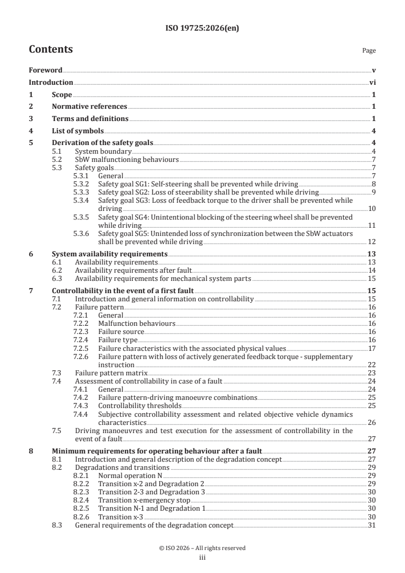
The document is organized into these main parts:
- Clause 1 - Scope
- Clause 2 - Normative references
- Clause 3 - Terms and definitions
- Clause 4 - List of symbols
- Clause 5 - Derivation of the safety goals
- Clause 6 - System availability requirements
- Clause 7 - Controllability in the event of a first fault
- Clause 8 - Minimum requirements for operating behaviour after a fault
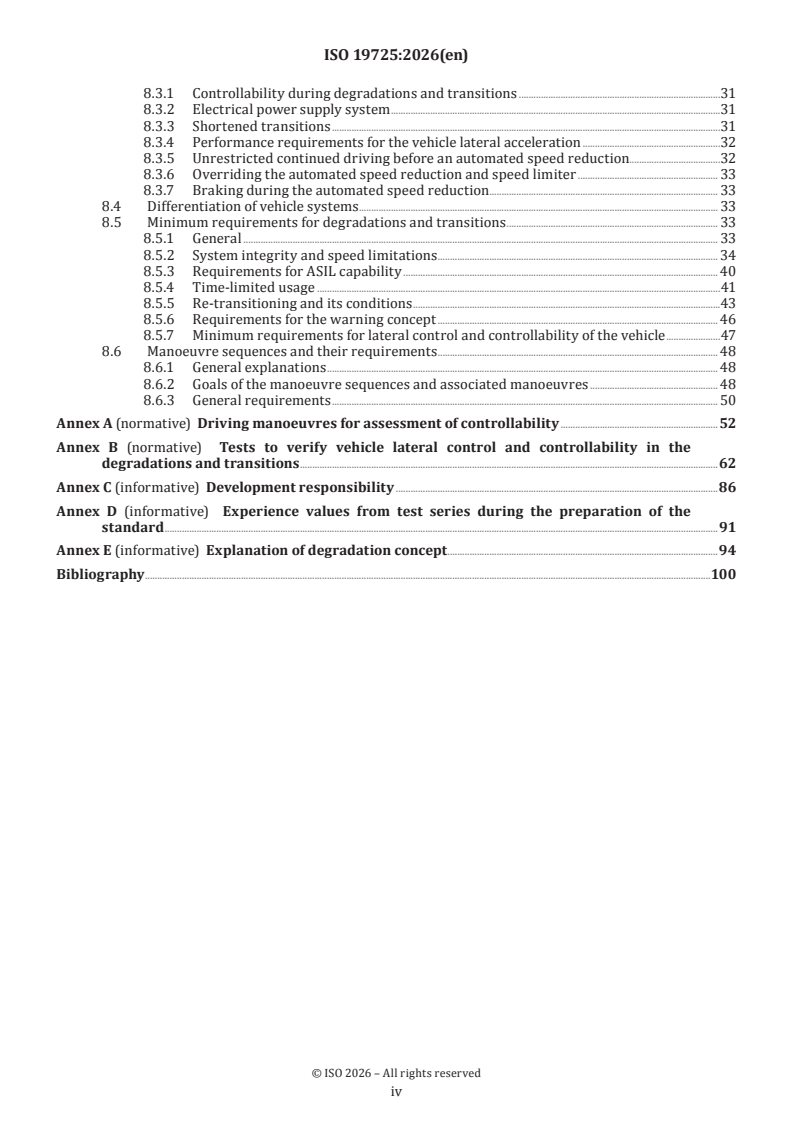
Annexes are split between test methods, implementation support, and explanatory material:
| Annex | What it covers |
|---|---|
| Annex A | Normative driving manoeuvres and test execution for controllability assessment after a first fault |
| Annex B | Normative tests to verify vehicle lateral control and controllability in degradations and transitions |
| Annex C | Informative development responsibility and example system breakdowns |
| Annex D | Informative experience values from test series used during preparation of the standard |
| Annex E | Informative explanation of the degradation concept |
What are the key requirements of ISO 19725:2026?
ISO 19725:2026 groups its requirements around safety goals, availability, first-fault controllability, and degraded operating behaviour. In practice, it asks the user to show that the SbW system keeps the vehicle steerable, warnable, and controllable long enough to reach a safe state after faults.
Clause 5 - safety goals and system boundary
ISO 19725:2026 defines the SbW system boundary as an electrically transmitted steering path where driver intention is sensed and sent to the actuator system, while steering feel is created by the HWA. Clause 5 identifies five safety goals: prevent self-steering, loss of steerability, loss of feedback torque, unintentional blocking of the steering wheel, and unintended loss of synchronization between the HWA and RWA while driving.
That matters because these are the fault effects the standard expects the safety concept to address. The clause ties the goals to the driver’s view of the fault, which helps engineers translate technical failures into vehicle-level hazards and safe states.
Clause 6 - system availability
ISO 19725:2026 separates safety-related availability from general availability. Safety-related availability is the ability to reach a safe state after a fault, while general availability is the ability to keep driving after faults that do not reduce ASIL capability.
In practice, the standard expects availability to come from the safety goals of the hazard analysis and risk assessment (HARA), from enough electrical and electronic (E/E) redundancy, and from enough energy to complete the transition to safe state. It also points out that supporting systems such as power supply and communication affect the overall result, even though their availability is not specified here.
Clause 6.2 adds a continued-driving expectation after faults that reduce ASIL capability. The vehicle should remain steerable and controllable long enough for the driver to stop safely or reach a safe parking position, with environmental conditions such as bridges, tunnels, construction sites, and highway exits considered in the timing. The standard refers to the shortest Emergency Operation Tolerance Time Interval (EOTTI) with a safety factor, and recommends a factor of the order of 10.
Clause 7 - controllability after a first fault
ISO 19725:2026 requires vehicle tests to evaluate controllability after a first fault. The minimum set uses an expert driver and combines failure patterns with road manoeuvres, then judges controllability both subjectively and with objective vehicle dynamics parameters.
The failure pattern matrix in Clause 7.3 is one of the most practical parts of the document. It covers 11 fault patterns linked to self-steering, loss of steerability, blocking, and loss of actively generated feedback torque, and it tells the user which failures and failure characteristics are to be tested together. In the tests, the fault input is varied to find the controllability threshold, and each variation is repeated at least four times in both steering directions.
Clause 7.5 requires a minimum set of manoeuvres: straight-ahead driving, steady-state circular driving, and slalom, each with defined speed or lateral acceleration and lane-width conditions. Annex A gives the detailed test configurations, hand positions, test-site setup, and acceptance criteria. This matters because the standard is not only asking for analysis - it also requires reproducible proving-ground testing.
Clause 8 - degraded operating behaviour after a fault
ISO 19725:2026 defines a degradation concept for continued operation after faults are mitigated. The vehicle can move through Normal operation N, Degradation 1, Degradation 2, and Degradation 3, with transitions such as N-1, x-2 Phases A/B/C, 2-3, x-3, and x-emergency stop.
The practical meaning is that the SbW system must not only fail safely, but also manage how the vehicle slows down, warns the driver, and reaches standstill or another safe state. Clause 8 includes requirements for system integrity, speed limitation, ASIL capability, time-limited usage, re-transitioning, the warning concept, and minimum lateral control and controllability during degradations and transitions.
The clause also allows other vehicle systems, such as brake, drivetrain, rear axle steering, ESC, and driver information systems, to support the degradation concept. That is important for integration work, because the SbW design is expected to fit into the wider vehicle safety concept rather than work alone.
What terms does ISO 19725:2026 define?
ISO 19725:2026 defines the terms that frame the safety concept and the test programme.
- Degradation - An operating condition within the degradation concept; in this document, normal operation N is also treated as a degradation condition.
- Degradation concept - All operating states after initial and subsequent faults, including transition states and normal operation N.
- Feedback torque - Torque on the steering wheel, either actively generated by the HWA or passively generated by driver rotation.
- Hand wheel actuator (HWA) - The component or components that sense steering wheel angle and provide feedback torque.
- Road wheel actuator (RWA) - The component or components that actuate the required road wheel angle on the front axle.
- Steerability - The ability of the SbW system to convert the driver’s steering wheel request into the intended steering movement of the road wheels.
- Vehicle lateral control - The ability to convert the steering request into the expected vehicle trajectory according to the available tire-road friction.
- Warning concept - Technical measures used to warn the driver and the environment when faults occur.
Who uses ISO 19725:2026?
ISO 19725:2026 is used by vehicle manufacturers, system suppliers, and safety engineers working on SbW for passenger cars and light commercial vehicles. It is also relevant for test engineers, validation teams, and proving-ground operators who need defined manoeuvres and acceptance criteria.
In practice, users apply it to:
- define the SbW item boundary and system architecture
- allocate development responsibility between OEM and supplier
- derive safety goals and safe states from HARA
- design redundancy, fallback, and warning strategies
- plan vehicle tests for controllability and degraded behaviour
- document test vehicles, test conditions, and measurement signals
Quality managers and buyers can use it to check whether an SbW development or test plan is aligned with a recognized safety guideline for series application.
Which standards are used with ISO 19725:2026?
ISO 19725:2026 explicitly uses ISO 15037-1, ISO 26262-1, and ISO 26262-3, and it also refers to ISO 26262-5 in the body and annexes.
- ISO 15037-1 - Provides general vehicle dynamics test conditions for passenger cars, which supports the manoeuvre-based testing in this document.
- ISO 26262-1 - Provides vocabulary and the basis for item definition and safety concepts.
- ISO 26262-3 - Supports the concept phase and the hazard analysis and risk assessment used to derive safety goals.
- ISO 26262-5 - Named in the text as the companion part for item and system architecture considerations and for safety metrics such as PMHF, SPFM, and LFM.
What does the ISO 19725:2026 document contain?
ISO 19725:2026 contains a symbols list, system-boundary figures, safety-goal explanations, a failure-pattern matrix, degradation-state diagrams, and detailed vehicle-test annexes. Annex A and Annex B provide the practical test set-ups, execution steps, and acceptance criteria needed for controllability and degraded-operation verification.
The document also includes informative material that helps users map the standard to real projects. Annex C gives example system breakdowns and development-responsibility sharing, Annex D summarizes experience values from preparatory test series, and Annex E explains the degradation concept with speed-limitation scenarios.
Get Certified
Connect with accredited certification bodies for this standard

TÜV Rheinland
TÜV Rheinland is a leading international provider of technical services.

TÜV SÜD
TÜV SÜD is a trusted partner of choice for safety, security and sustainability solutions.

DEKRA Certification Inc.
DEKRA US certification services.
Sponsored listings
Frequently Asked Questions
ISO 19725:2026 is a standard published by the International Organization for Standardization (ISO). Its full title is "Road vehicles — Steer-by-wire systems — System safety guidelines". This standard covers: This document specifies necessary but not sufficient safety requirements for the use of SbW systems in passenger cars and light commercial vehicles for series application. This document does not replace the full application of the ISO 26262 series of standards and their implementation in safety-related measures. This document defines requirements for manual driving where the driver holds the steering wheel. NOTE Misuse of hands-free driving is not considered. This document does not contain any requirements for the use of automated lateral vehicle control functions. The requirements consider systems consisting of a road wheel actuator (RWA), hand wheel actuator (HWA), and a steering wheel for driver input. Deviating concepts need to be analysed by the user for transferability.
This document specifies necessary but not sufficient safety requirements for the use of SbW systems in passenger cars and light commercial vehicles for series application. This document does not replace the full application of the ISO 26262 series of standards and their implementation in safety-related measures. This document defines requirements for manual driving where the driver holds the steering wheel. NOTE Misuse of hands-free driving is not considered. This document does not contain any requirements for the use of automated lateral vehicle control functions. The requirements consider systems consisting of a road wheel actuator (RWA), hand wheel actuator (HWA), and a steering wheel for driver input. Deviating concepts need to be analysed by the user for transferability.
ISO 19725:2026 is classified under the following ICS (International Classification for Standards) categories: 43.040.99 - Other road vehicle systems. The ICS classification helps identify the subject area and facilitates finding related standards.
ISO 19725:2026 is available in PDF format for immediate download after purchase. The document can be added to your cart and obtained through the secure checkout process. Digital delivery ensures instant access to the complete standard document.
Standards Content (Sample)
International
Standard
ISO 19725
First edition
Road vehicles — Steer-by-wire
2026-05
systems — System safety guidelines
Véhicules routiers — Systèmes de direction électronique — Lignes
directrices sur la sécurité du système
Reference number
© ISO 2026
All rights reserved. Unless otherwise specified, or required in the context of its implementation, no part of this publication may
be reproduced or utilized otherwise in any form or by any means, electronic or mechanical, including photocopying, or posting on
the internet or an intranet, without prior written permission. Permission can be requested from either ISO at the address below
or ISO’s member body in the country of the requester.
ISO copyright office
CP 401 • Ch. de Blandonnet 8
CH-1214 Vernier, Geneva
Phone: +41 22 749 01 11
Email: copyright@iso.org
Website: www.iso.org
Published in Switzerland
ii
Contents Page
Foreword .v
Introduction .vi
1 Scope . 1
2 Normative references . 1
3 Terms and definitions . 1
4 List of symbols . 4
5 Derivation of the safety goals. 4
5.1 System boundary . .4
5.2 SbW malfunctioning behaviours .7
5.3 Safety goals .7
5.3.1 General .7
5.3.2 Safety goal SG1: Self-steering shall be prevented while driving .8
5.3.3 Safety goal SG2: Loss of steerability shall be prevented while driving .9
5.3.4 Safety goal SG3: Loss of feedback torque to the driver shall be prevented while
driving .10
5.3.5 Safety goal SG4: Unintentional blocking of the steering wheel shall be prevented
while driving .11
5.3.6 Safety goal SG5: Unintended loss of synchronization between the SbW actuators
shall be prevented while driving . 12
6 System availability requirements .13
6.1 Availability requirements . 13
6.2 Availability requirements after fault .14
6.3 Availability requirements for mechanical system parts . 15
7 Controllability in the event of a first fault .15
7.1 Introduction and general information on controllability . 15
7.2 Failure pattern .16
7.2.1 General .16
7.2.2 Malfunction behaviours .16
7.2.3 Failure source .16
7.2.4 Failure type .16
7.2.5 Failure characteristics with the associated physical values .17
7.2.6 Failure pattern with loss of actively generated feedback torque - supplementary
instruction . 22
7.3 Failure pattern matrix . 23
7.4 Assessment of controllability in case of a fault .24
7.4.1 General .24
7.4.2 Failure pattern-driving manoeuvre combinations . . 25
7.4.3 Controllability thresholds . 25
7.4.4 Subjective controllability assessment and related objective vehicle dynamics
characteristics . 26
7.5 Driving manoeuvres and test execution for the assessment of controllability in the
event of a fault .27
8 Minimum requirements for operating behaviour after a fault .27
8.1 Introduction and general description of the degradation concept .27
8.2 Degradations and transitions . 29
8.2.1 Normal operation N . 29
8.2.2 Transition x-2 and Degradation 2 . 29
8.2.3 Transition 2-3 and Degradation 3 . 30
8.2.4 Transition x-emergency stop . 30
8.2.5 Transition N-1 and Degradation 1 . 30
8.2.6 Transition x-3 . 30
8.3 General requirements of the degradation concept.31
iii
8.3.1 Controllability during degradations and transitions .31
8.3.2 Electrical power supply system .31
8.3.3 Shortened transitions .31
8.3.4 Performance requirements for the vehicle lateral acceleration .32
8.3.5 Unrestricted continued driving before an automated speed reduction.32
8.3.6 Overriding the automated speed reduction and speed limiter . 33
8.3.7 Braking during the automated speed reduction. 33
8.4 Differentiation of vehicle systems . . 33
8.5 Minimum requirements for degradations and transitions . 33
8.5.1 General . 33
8.5.2 System integrity and speed limitations . 34
8.5.3 Requirements for ASIL capability . 40
8.5.4 Time-limited usage .41
8.5.5 Re-transitioning and its conditions .43
8.5.6 Requirements for the warning concept . 46
8.5.7 Minimum requirements for lateral control and controllability of the vehicle .47
8.6 Manoeuvre sequences and their requirements . 48
8.6.1 General explanations . 48
8.6.2 Goals of the manoeuvre sequences and associated manoeuvres . 48
8.6.3 General requirements . 50
Annex A (normative) Driving manoeuvres for assessment of controllability .52
Annex B (normative) Tests to verify vehicle lateral control and controllability in the
degradations and transitions .62
Annex C (informative) Development responsibility .86
Annex D (informative) Experience values from test series during the preparation of the
standard .91
Annex E (informative) Explanation of degradation concept .94
Bibliography .100
iv
Foreword
ISO (the International Organization for Standardization) is a worldwide federation of national standards
bodies (ISO member bodies). The work of preparing International Standards is normally carried out through
ISO technical committees. Each member body interested in a subject for which a technical committee
has been established has the right to be represented on that committee. International organizations,
governmental and non-governmental, in liaison with ISO, also take part in the work. ISO collaborates closely
with the International Electrotechnical Commission (IEC) on all matters of electrotechnical standardization.
The procedures used to develop this document and those intended for its further maintenance are described
in the ISO/IEC Directives, Part 1. In particular, the different approval criteria needed for the different types
of ISO document should be noted. This document was drafted in accordance with the editorial rules of the
ISO/IEC Directives, Part 2 (see www.iso.org/directives).
ISO draws attention to the possibility that the implementation of this document may involve the use of (a)
patent(s). ISO takes no position concerning the evidence, validity or applicability of any claimed patent
rights in respect thereof. As of the date of publication of this document, ISO had received notice of (a)
patent(s) which may be required to implement this document. However, implementers are cautioned that
this may not represent the latest information, which may be obtained from the patent database available at
www.iso.org/patents. ISO shall not be held responsible for identifying any or all such patent rights.
Any trade name used in this document is information given for the convenience of users and does not
constitute an endorsement.
For an explanation of the voluntary nature of standards, the meaning of ISO specific terms and expressions
related to conformity assessment, as well as information about ISO's adherence to the World Trade
Organization (WTO) principles in the Technical Barriers to Trade (TBT), see www.iso.org/iso/foreword.html.
This document was prepared by Technical Committee ISO/TC 22, Road vehicles, Subcommittee SC 33, Vehicle
dynamics, chassis components and driving automation systems testing.
Any feedback or questions on this document should be directed to the user’s national standards body. A
complete listing of these bodies can be found at www.iso.org/members.html.
v
Introduction
Steer-by-Wire (SbW) systems represent the next generation of technology in vehicle steering. They enable
new interior concepts and pave the way for further innovations in vehicle technology. In the context of
automated driving, mechanical decoupling between the steering wheel and the steered wheels is becoming
increasingly important. To date, there is no experience of widespread use of this technology in the market
for large-series passenger cars.
Compared to conventional steering systems, SbW technology results in additional requirements for the
safety concept of the vehicle for safe operation.
This document represents a description of a minimal set of safety aspects developed by vehicle manufacturers
and system suppliers.
This document considers:
— the description and system boundary of an SbW system,
— basic safety goals,
— general availability requirements,
— requirements for controllability in the event of a first fault, and
— requirements for the operational behaviour after a fault event.
vi
International Standard ISO 19725:2026(en)
Road vehicles — Steer-by-wire systems — System safety
guidelines
1 Scope
This document specifies necessary but not sufficient safety requirements for the use of SbW systems in
passenger cars and light commercial vehicles for series application.
This document does not replace the full application of the ISO 26262 series of standards and their
implementation in safety-related measures.
This document defines requirements for manual driving where the driver holds the steering wheel.
NOTE Misuse of hands-free driving is not considered.
This document does not contain any requirements for the use of automated lateral vehicle control functions.
The requirements consider systems consisting of a road wheel actuator (RWA), hand wheel actuator (HWA),
and a steering wheel for driver input. Deviating concepts need to be analysed by the user for transferability.
2 Normative references
The following documents are referred to in the text in such a way that some or all of their content constitutes
requirements of this document. For dated references, only the edition cited applies. For undated references,
the latest edition of the referenced document (including any amendments) applies.
ISO 15037-1:2019, Road vehicles — Vehicle dynamics test methods — Part 1: General conditions for passenger
cars
ISO 15037-1, Road vehicles — Vehicle dynamics test methods — Part 1: General conditions for passenger cars
ISO 26262-1, Road vehicles — Functional safety — Part 1: Vocabulary
ISO 26262-3, Road vehicles — Functional safety — Part 3: Concept phase
3 Terms and definitions
For the purposes of this document, the terms and definitions given in ISO 26262-1 and the following apply.
ISO and IEC maintain terminology databases for use in standardization at the following addresses:
— ISO Online browsing platform: available at https:// www .iso .org/ obp
— IEC Electropedia: available at https:// www .electropedia .org/
3.1
degradation
degradation stage
DEG
operating conditions of the vehicle within the framework of the degradation concept (3.2)
Note 1 to entry: Due to the operating condition of the steering system or supporting systems, a degradation condition
can lead to restrictions in the use of the vehicle, e.g. speed limitations. Normal operation N is treated as degradation
condition in this document.
3.2
degradation concept
all operating states of the vehicle, including the operating states of the steering system and the supporting
vehicle systems after initial and subsequent faults
Note 1 to entry: Operating states include both transition and degradation states after faults, as well as the fault-free
normal operation N.
3.3
drive cycle
time span from start to end of a trip
Note 1 to entry: In this document, the term is used in the context of re-transitioning between degradation states.
3.4
expert driver
person who has above-average vehicle dynamics knowledge, skills, ability to assess controllability, capability
to conduct the vehicle tests and has regular driving experience
3.5
feedback torque
torque on the steering wheel
Note 1 to entry: An actively generated feedback torque occurs when at least one drive unit of the HWA is active. A
passively generated feedback torque occurs when no drive unit of the HWA is active and the driver performs a steering
wheel rotation. The feedback torque is used, among other things, to represent the steering feel.
3.6
hand wheel actuator
HWA
component(s) sensing the steering wheel angle and providing a feedback torque (3.5)
3.7
immobilization
process in which a stationary vehicle is secured against rolling away
3.8
lane
lateral limited area for the movement of the vehicle, within which the driving task is to be accomplished
3.9
manoeuvre
specified road test
3.10
vehicle lateral manoeuvrability
ability of the vehicle to convert the steering wheel angle request of the driver into a minimal lateral motion
reaction while driving below 10 km/h
3.11
manoeuvre sequence
MS
specific group of tests
3.12
normal driver
person who does not have special skills to drive a vehicle
Note 1 to entry: Used to distinguish from expert driver.
3.13
normal operation
N
condition of the steering system and the supporting vehicle systems without safety-critical faults
Note 1 to entry: Minor, non-safety critical deviations within the nominal application range are permissible. The
deviation of the behaviour of the steering system and the vehicle relative to the nominal behaviour is within the range
expected by the driver.
3.14
passive fallback level
〈HWA〉 operating condition at which no active feedback torque is generated
Note 1 to entry: A passive fallback of an HWA can be mechanical base friction or a damping (e.g. electromagnetic,
magneto-resistive, back EMF).
3.15
positive diagnostic re-check
diagnostic measure that confirms a previously detected fault is no longer present
3.16
road wheel actuator
RWA
component(s) for actuating the required road wheel angle on the front axle
3.17
steerability
ability of the SbW system to convert the steering wheel angle request of the driver into a design-intended
steering movement of the road wheels of the vehicle
3.18
system integrity
characteristics of the SbW system including ASIL capability to meet functional and availability requirements
Note 1 to entry: Functional requirements concern e.g. steering performance, feedback torque and synchronicity.
Availability requirements concern e.g. redundancies to maintain steering capability.
Note 2 to entry: Degradation of steering performance or loss of redundancy can reduce the ASIL capability .
3.19
test configuration
combination of the configuration of the test vehicle (see Annex B, B.2.2) and the configurations of the
respective vehicle systems (see Annex B, B.2.3) for the tests to demonstrate steerability or vehicle lateral
control and controllability in the degradations and transitions
3.20
transition
TR
change between degradation states
Note 1 to entry: A transition represents a time-limited state of a steering system and vehicle. Due to the system state
of the steering system or supporting systems, a transition can lead to restrictions in the use of the vehicle, e.g. speed
limits.
3.21
vehicle lateral control
ability of the vehicle to convert the steering wheel angle request of the driver into an expected vehicle
trajectory according to the available friction coefficient between the tire and the road surface
Note 1 to entry: A trajectory change is also realized by other vehicle systems (e.g. brake, drivetrain, powertrain etc.)
beyond the SbW system.
3.22
warning concept
technical measures to warn the driver and the environment in case of faults
3.23
warning symbol
standardized symbol for feedback to the driver of a failure or a degradation state of the SbW system
4 List of symbols
Table 1 — List of used symbols
Size Symbol Unit
Vehicle lateral acceleration a m/s
y
Vehicle longitudinal acceleration a m/s
x
Distance a m
Vehicle width B m
Lane width b m
Wheelbase L m
Pylons distance d m
Circle radius R/R m
i
Track length S m
Vehicle speed v km/h
x
Vehicle speed at the beginning of the
v km/h
x Start
manoeuvre
Vehicle speed at the end of the ma-
v km/h
x End
noeuvre
Disturbance yaw rate
°/s
Δ
Disturbance lateral acceleration Δa m/s
y
Fault duration t s
Fault
5 Derivation of the safety goals
5.1 System boundary
SbW is a steering system in which the driver's steering intention is detected by a sensor system and
transmitted exclusively electrically to the actuator system to apply the road wheel angle. The steering feel is
represented to the driver by means of an HWA.
Compared with conventional steering systems (e.g. electromechanical steering, superimposed steering),
there is no mechanical connection between the steering wheel and the steered wheels in an SbW system. This
conceptual difference results in additional safety requirements and safety-related availability requirements
for the steering system in the vehicle.
For an SbW system, steerability or vehicle lateral control shall be maintained during driving despite an
electrical fault in the SbW system or in other supporting systems in the vehicle (e.g. vehicle power supply
system, vehicle communication).
Figure 1 shows an example of the item SbW according to ISO 26262-1 with the system boundaries of the
item, the interfaces to the vehicle as well as functional elements. In addition, the control chains of the two
main functions of an SbW system are also shown:
— provide steerability and
— provide feedback torque.
Key
1 measurement of the steering wheel angle
2 actuation of feedback torque via steering wheel (steering feel including haptic warning)
3 target road wheel angle
4 measured variables of actuators
5 road wheel angle (transmission through the mechanical linkage via tie rod and steering linkage to the front
wheels)
6 visual or audible information and warnings from the SbW system
7 interaction between wheels and road
8 power supply
9 information exchange
Figure 1 — Definition of item for SbW
An SbW system with the specified functions is defined as one item according to the definition in ISO 26262-1
[1]
and ISO 26262-5 .
The item SbW can either be defined as one system or as a combination of several systems according to
[1]
ISO 26262-1 and ISO 26262-5 , see Figure 2 and Figure 3.
Key
1 steering wheel input
2 feedback torque (steering feel including haptic warning)
3 road wheel angle
[2]
Figure 2 — Option 1: Definition of system(s) for SbW according to the ISO 26262 series
Key
1 steering wheel input
2 feedback torque (steering feel including haptic warning)
3 road wheel angle
4 information exchange between systems
[2]
NOTE The definition "1 item = n systems (2 ≤ n ≤ 10)" follows the requirements of the ISO 26262 series .
[2]
Figure 3 — Option 2: Definition of system(s) for SbW according to the ISO 26262 series
An example of breakdown in physical system architecture(s) for both variants and for the share of
development responsibilities between OEM and supplier is given in Annex C.
5.2 SbW malfunctioning behaviours
Based on the functions of the SbW system listed in 5.1:
— provide steerability, and
— provide feedback torque,
the following SbW malfunctioning behaviours are considered:
— self-steering;
— loss of steerability;
— loss of feedback torque;
— blocking of the steering system;
— loss of synchronization between steering wheel angle and road wheel angle.
The malfunctioning behaviours are defined from driver's perspective, that means they represent a faulty
behaviour as it can be experienced by the driver:
— "self-steering" can occur if the road wheels are unintentionally moved
— due to a fault in the function "Provide steerability" (e.g. faults in the measurement, signal processing,
actuation), or
— due to a fault in the function "Provide feedback torque" (e.g. faults in the measurement, signal
processing, actuation) leading to an unintended movement of the steering wheel,
— "loss of steerability" can occur if the driver's intention is not actuated at the road wheels;
— "loss of feedback torque" can occur if no or insufficient torque is applied to the steering wheel;
— "blocking of the steering system" can occur if the forces to rotate the steering wheel are too high for the
driver;
— "loss of synchronization between steering wheel angle and road wheel angle" can occur if the road wheel
angle and steering wheel angle are misaligned, e.g. due to
— delayed road wheel angle actuation,
— misalignment at vehicle wake-up.
In addition to the above listed malfunctions, a complete analysis of all E/E malfunctions in accordance with
ISO 26262-3 as well as mechanical failures shall be conducted for a specific SbW system.
5.3 Safety goals
5.3.1 General
The following safety goals and their criticality ratings are derived from the SbW malfunctioning behaviours
listed in 5.2:
— SG1: Self-steering shall be prevented while driving.
— SG2: Loss of steerability shall be prevented while driving.
— SG3: Loss of feedback torque to the driver shall be prevented while driving.
— SG4: Unintentional blocking of the steering wheel shall be prevented while driving.
— SG5: Unintended loss of synchronization between the SbW actuators shall be prevented while driving.
Table 2 shows the allocation of the SbW malfunctioning behaviours to the safety goals.
Table 2 — Allocation of SbW malfunctions to safety goals
Function of SbW system SbW malfunction Safety goals
Provide steerability Self-steering (RWA) SG1
Loss of steerability SG2
Blocking of the steering system
(RWA)
Loss of synchronization between SG5
steering wheel angle and road wheel
angle
Provide feedback torque Self-Steering (HWA) SG1
Loss of feedback torque SG3
Blocking of the steering system SG4
(HWA)
NOTE 1 In the context of the safety goals, "while driving" means that the vehicle is in a state where the driver has
lateral and longitudinal control of the vehicle. The criticality (ASIL rating) of a safety goal violation is speed dependent.
At very low speeds (e.g. 10 km/h with a corresponding warning concept), the risk is much lower than at higher speeds
due to the significantly reduced kinetic energy.
NOTE 2 This document evaluates the criticality of the safety goals for E/E faults with Automotive Safety Integrity
[2]
Level (ASIL) according to ISO 26262 series .
NOTE 3 The SbW malfunction “blocking of the steering system” as per 5.2 can be caused by blocking of the HWA
(SG4) or blocking of the RWA (SG2).
The listed safety goals are not derived from a complete hazard analysis and risk assessment according to
[2]
ISO 26262 series but are based on the generic failure modes. Therefore, the listed safety goals represent
only a minimum set of safety goals.
This document does not relieve the user from performing a complete HARA according to ISO 26262-3 for a
specific SbW system.
5.3.2 Safety goal SG1: Self-steering shall be prevented while driving
5.3.2.1 Explanation
Self-steering is an unintended steering angle change (RWA and/or HWA) caused by a unintended force of the
RWA or an unintended torque of the HWA. The safety goal is classified as ASIL D.
EXAMPLE Possible causes for an unintended RWA force or an unintended feedback torque including failures in
the entire control path: sensors, communication, control and actuators. The type of unintended actuator control can
follow different failure patterns, e.g. wrong amplitude, overshoot, wrong direction, superimposed, oscillating.
5.3.2.2 Acceptance criteria
Faults in an SbW system which can lead to the violation of the safety goal shall be mitigated in a suitable
manner. It has to be ensured that the vehicle can be kept in the lane (see Clause 7).
5.3.2.3 Safe state vehicle
The safe state on vehicle level for the function "provide steerability" is reached when the vehicle speed is
reduced to ≤ 10 km/h with a corresponding warning.
The safe state on vehicle level for the function "Provide feedback torque" is reached when general
controllability (C0 controllability) is given or when the vehicle speed is reduced to ≤ 10 km/h with
appropriate warning.
[3]
NOTE UN Regulation No. 79 refers to the threshold of ≤ 10 km/h in the event of a fault. Depending on driving
situations, furthermore the degradation concept defines the transition of the vehicle into vehicle standstill within the
vehicle safe state.
When transitioning the vehicle to the safe state, the requirements of the degradation concept shall be met
(see Clause 8).
The safe state at vehicle level can only be reached and ensured by considering systems outside the SbW
system or considering the driver.
5.3.2.4 Safe state SbW system
The safe state on SbW system level for the function "Provide steerability" is to continue the operation
of the function until the safe state is reached at the vehicle level. Faulty components shall be isolated or
deactivated. Remaining required redundancies are to be activated or maintained.
The safe state on SbW system level for the function "Provide feedback torque" is to continue the operation of
the function until the safe state at the vehicle level is reached or internal SbW mechanism exists where the
functionality of the active feedback torque is no longer required for safety reasons. Faulty components shall
be isolated or deactivated. Remaining required redundancies shall be activated or kept active or alternative
mitigation measures shall be applied.
EXAMPLE Example mitigation measures can be increased mechanical friction or damping.
In order to prevent violation of other safety goals, following additional measures shall be considered:
— remaining redundant control and power supply channels shall be activated or kept active;
— minimum steering performance according to the degradation concept shall be ensured.
5.3.3 Safety goal SG2: Loss of steerability shall be prevented while driving
5.3.3.1 Explanation
Loss of the steerability is a failure in the SbW system that leads to the loss of the function “Provide
steerability” and cannot be sufficiently compensated by other systems for vehicle lateral control. The safety
goal is classified as ASIL D.
EXAMPLE Possible failure causes for a failure of the steerability include the entire control path: sensors,
communication, control, actuators, power supply, as well as mechanical components.
5.3.3.2 Acceptance criteria
In the event of faults in an SbW system which can lead to the violation of the safety goal shall be mitigated
in a suitable manner. It shall be ensured that the vehicle can be kept in the lane (see Clause 7). The minimum
steering performance shall be ensured in accordance with the degradation concept (see Clause 8).
5.3.3.3 Safe state vehicle
The safe state on vehicle level is reached when the vehicle speed is reduced to ≤ 10km/h with appropriate
warning.
[3]
NOTE 1 UN Regulation No. 79 refers to the threshold of ≤ 10 km/h in the event of a fault. Depending on driving
situations, furthermore the degradation concept defines the transition of the vehicle into vehicle standstill within
the vehicle safe state. The safe state with corresponding driver warning is a sufficient risk mitigation according to
[2]
ISO 26262 series . The residual risk of a loss of steerability at vehicle speeds ≤ 10km/h with corresponding driver
warning does not lead to an ASIL classification.
A minimum vehicle lateral manoeuvrability shall be ensured while continuing driving within the safe state.
If steerability or vehicle lateral control is completely lost, an automated deceleration to standstill shall be
executed as long as the automated deceleration is still operational (see Clause 8).
NOTE 2 Previous experiences indicate that drivers try to control the vehicle by more steering angle input, instead
of immediately braking. The reaction of the driver to brake the vehicle to standstill can be delayed.
When transitioning the vehicle to the safe state, the requirements of the degradation concept shall be met
(see Clause 8).
The safe state at vehicle level can only be reached and ensured by considering systems outside the SbW
system or considering the driver.
5.3.3.4 Safe state SbW system
The safe state on SbW system level for the function "Provide steerability" is to continue the operation
of the function until the safe state is reached at the vehicle level. Faulty components shall be isolated or
deactivated. Remaining required redundancies shall be activated or maintained.
5.3.4 Safety goal SG3: Loss of feedback torque to the driver shall be prevented while driving
5.3.4.1 Explanation
Loss of feedback torque is a fault in the SbW system that results in a loss of the function "Provide feedback
torque”. The safety goal is classified as minimum ASIL B. The criticality for loss of feedback torque can vary
depending on system design and characteristics of the transfer function (e.g. differences in friction, steering
ratio).
EXAMPLE Possible failure causes for a loss of the feedback torque include the entire control path: sensors,
communication, control, actuators, power supply, as well as mechanical components. The effect of faults can lead to a
partial loss or even to a complete loss of the feedback torque.
5.3.4.2 Acceptance criteria
Two aspects regarding controllability shall be considered in case of faults leading to loss of feedback torque.
Faults in an SbW system that can lead to the violation of the safety goal shall be mitigated in an appropriate
manner. It shall be ensured that the vehicle can be kept in the lane (see Clause 7).
In addition, the remaining substitute functions (e.g. redundancy, friction, damping) shall ensure
controllability of the vehicle to continue driving (see Clause 8).
5.3.4.3 Safe state vehicle
The safe state on vehicle level is reached when general controllability (C0 controllability) is given or when
the vehicle speed is reduced to ≤ 10 km/h with appropriate warning.
[3]
NOTE UN Regulation No. 79 refers to the threshold of ≤ 10 km/h in the event of a fault. Depending on driving
situations, furthermore the degradation concept defines the transition of the vehicle into vehicle standstill within the
vehicle safe state. When transitioning the vehicle to the safe state, the requirements of the degradation concept shall
be met (see Clause 8).
If the safe state cannot be achieved with general controllability, the safe state can only be reached and
ensured at the vehicle level by considering systems outside the SbW system or considering the driver.
5.3.4.4 Safe state SbW system
The safe state on SbW system level for the function "Provide feedback torque" is to continue the operation of
the function until the safe state at the vehicle level is reached or internal SbW mechanism exists where the
functionality of the active feedback torque is no longer required for safety reasons. Faulty components shall
be isolated or deactivated. Remaining required redundancies shall be activated or kept active or alternative
mitigation measures shall be applied.
EXAMPLE Example mitigation measures can be increased mechanical friction or damping.
5.3.5 Safety goal SG4: Unintentional blocking of the steering wheel shall be prevented while driving
5.3.5.1 Explanation
An unintentional excessive feedback torque acting against the driver's steering wheel rotation (high
steering resistance up to blocking of the HWA) shall be prevented. This includes both, electromechanically
and mechanically caused high steering resistance up to blocking. The safety goal is classified as ASIL D.
EXAMPLE 1 Possible electromechanical faults causing excessive feedback torque include the entire control path:
sensors, communication, control, actuators. Examples include simulation of the unintended dynamic end stop due to
an incorrect steering angle or an unintended phase short-circuit in the HWA.
EXAMPLE 2 Possible mechanical causes for excessive feedback torque include the mechanical components, e.g.
wrong mechanical end stop position leading to blocking or increased friction leading to high steering resistance.
NOTE 1 SG4 differs from SG1. Fault leading to violation of SG4 does not lead to any active steering wheel rotation.
The steering wheel rotation by the driver is inhibited or limited.
NOTE 2 SG4 differs from SG2. SG4 is not violated, in case of an intended inhibited steering wheel rotation as
additional mitigation in case of SG2 violation, e.g. blocked RWA.
5.3.5.2 Acceptance criteria
Two aspects regarding controllability shall be considered in case of faults leading to unintentionally blocking
of the steering wheel.
Faults in an SbW system that can lead to the violation of the safety goal shall be mitigated in a suitable
manner. It shall be ensured that the vehicle can be kept in the lane (see Clause 7).
In addition, the remaining substitute functions (e.g. redundancy, friction, damping) shall be ensure
controllability of the vehicle to continue driving (see Clause 8).
5.3.5.3 Safe state vehicle
The safe state on vehicle level is reached when general controllability (C0 controllability) is given or when
the vehicle speed is reduced to ≤ 10 km/h with appropriate warning.
[3]
NOTE UN Regulation No. 79 refers to the threshold of ≤ 10 km/h in the event of a fault. Depending on driving
situations, furthermore the degradation concept defines the transition of the vehicle into vehicle standstill within the
vehicle safe state.
When transitioning the vehicle to the safe state, the requirements of the degradation concept shall be met
(see Clause 8).
If the safe state cannot be achieved by general controllability, the safe state can only be reached and ensured
at the vehicle level by considering systems outside the SbW system or considering the driver.
5.3.5.4 Safe state SbW system
The safe state on SbW system level for the function "Provide feedback torque" is to continue the operation of
the function u
...