

oSIST prEN IEC 61851-24:2026
(Main)Conductive power and energy transfer systems for electric vehicles - Part 24: Digital communication between a DC EV supply equipment and an electric vehicle for control of DC charging
- Status
- Not Published
- Public Enquiry End Date
- 29-Nov-2026
- Technical Committee
- CEV - Electric passenger and commercial vehicles
- Current Stage
- 4020 - Public enquire (PE) (Adopted Project)
- Start Date
- 22-Sep-2026
- Due Date
- 09-Feb-2027

oSIST prEN IEC 61851-24:2026 is a CLC document for digital communication between a DC electric vehicle supply equipment (EVSE) and an electric vehicle (EV) during conductive DC charging. It specifies the communication architectures, message exchanges, and system-specific procedures used to control DC charging, so it is mainly relevant to charger and vehicle designers, communication engineers, and test teams.
What does oSIST prEN IEC 61851-24:2026 specify?
oSIST prEN IEC 61851-24:2026 covers digital communication for control of conductive DC power transfer between an EVSE and an EV. It applies up to the stated supply and output voltage limits, uses mode 4 charging, and includes a specific application for DC EV charging/discharging station system A.
The document is organized into core clauses plus four normative annexes and a bibliography.
| Annex | What it covers |
|---|---|
| Annex A | Digital communication for control of DC EV charging system A, including charging and bi-directional charging/discharging |
| Annex B | Digital communication for control of DC charging of upgraded system B, including version negotiation and backward compatibility |
| Annex C | Digital communication for control of DC charging system C, based on ISO 15118 communication |
| Annex D | Digital communication for control of DC charging system D, including CAN-based communication and two-wire Ethernet |
Clause 5 describes the communication architectures, Clause 6 links the communication to the charging process, and Clause 8 defines the information exchanged during DC charging control. Annexes A to D then give the system-specific procedures and parameter sets.
What are the key requirements of oSIST prEN IEC 61851-24:2026?
The main requirement of oSIST prEN IEC 61851-24:2026 is that the EVSE and EV exchange defined control information in a controlled sequence before, during, and after DC charging. In practice, the standard is about making sure both sides agree on limits, status, safety checks, and stop conditions before energy transfer continues.
Clause 5 - communication architecture
- oSIST prEN IEC 61851-24:2026 defines two communication architectures: CAN over a dedicated data communication circuit, and Homeplug® Green PHY™ over the control pilot line. This matters because an implementation must choose the correct physical and protocol layer before any charging messages can be exchanged.
Clause 8 - common exchanged information
- oSIST prEN IEC 61851-24:2026 identifies the information that is common to all systems, such as current request, voltage request, EVSE maximum limits, communication protocol version, insulation check result, short circuit test, user stop command, loss of digital communication, zero current confirmed, welding detection, and shutdown status. This gives engineers the shared data model they must map into the system-specific messages.
Annex A - system A charging control
- oSIST prEN IEC 61851-24:2026 Annex A defines the charging sequence for system A, including communication actions from plug-in through initialization, handshaking, pre-charge, current or voltage demand, energy transfer, and shutdown. It also covers optional functions such as dynamic control and charging with thermal management system, so a system A implementation can support more than the basic charge flow.
- Annex A also defines CAN-based physical and data link layer requirements, including a dedicated CAN communication circuit, termination resistor, noise filtering, twisted-pair line, and reception error handling. In practice, this means the charger must detect communication loss and stop charging if frames are not received for the defined period.
- Annex A further covers bi-directional power flow for charging and discharging, so the same annex supports vehicle-to-grid-style control cases where the energy direction can change.
Annex B - upgraded system B
- oSIST prEN IEC 61851-24:2026 Annex B defines version negotiation, function negotiation, parameter configuration, authentication, scheduled mode, cable check, power supply mode, pre-charge and energy transfer, and shutdown for upgraded system B. This matters because the charger and vehicle must agree on the protocol version and supported functions before charging starts.
- Annex B also defines backward compatibility via version negotiation. That is important for mixed fleets, because a charger can fall back to the legacy system B communication protocol if the upgraded version cannot be agreed.
Annex C - system C
- oSIST prEN IEC 61851-24:2026 Annex C states that system C shall support at least ISO 15118-2:2014 or ISO 15118-20:2022 together with ISO 15118-20:2022/Amd1:202X. For RPT or BPT, ISO 15118-20 and its amendment are required. This means system C is intended for implementations that use ISO 15118-style network and application messaging.
- Annex C ties the common charging-control information to ISO 15118 message objects, so the reader can see how the Table 1 parameters are carried in that protocol.
Annex D - system D
- oSIST prEN IEC 61851-24:2026 Annex D defines system D communication using either CAN-based digital communication or two-wire Ethernet digital communication. It sets out function modules such as Function Negotiation, Parameter configuration, Self-check, Pre-charge and energy transfer, Service statistics, and Idle.
- Annex D also defines layered communication, message types, version negotiation, and reliable and unreliable transport behavior. In practice, this makes Annex D a protocol framework for software that must negotiate features and exchange structured messages, not just raw control values.
What terms does oSIST prEN IEC 61851-24:2026 define?
- Electric vehicle supply equipment (EVSE) - The charger or supply equipment that communicates with the vehicle to control DC charging.
- Electric vehicle (EV) - The vehicle that exchanges charging-control parameters with the EVSE.
- Supply equipment communication controller (SECC) - The EVSE-side communication controller identified in the overview figure.
- EV communication controller (EVCC) - The vehicle-side communication controller identified in the overview figure.
- Controller area network (CAN) - The dedicated in-vehicle communication method used in several annexes for charging control.
- Controlled current charging (CCC) - A charging mode where the vehicle requests current.
- Controlled voltage charging (CVC) - A charging mode where the vehicle requests voltage.
- Parameter - A single piece of charging-control information exchanged between the EVSE and the EV by digital communication.
Who uses oSIST prEN IEC 61851-24:2026?
oSIST prEN IEC 61851-24:2026 is used by EVSE manufacturers, EV manufacturers, and communication-software developers who need the charger and the vehicle to exchange compatible control messages. It is also used by test laboratories, conformity assessment teams, and quality managers who need to verify message sets, timing, and handshake behavior.
System integrators and buyers of DC charging equipment use it to compare whether a charger supports the same communication system as the vehicle fleet they plan to serve. For operational teams, the document is useful when checking interoperability between charging hardware, vehicle software, and protocol variants such as systems A, B, C, and D.
What changed in oSIST prEN IEC 61851-24:2026 from the previous edition?
This second edition cancels and replaces the first edition published in 2014. The stated technical revision updates Annex A and Annex B in line with IEC 61851-23:202X and relevant standards.
Which standards are used with oSIST prEN IEC 61851-24:2026?
| Reference | What it contributes |
|---|---|
| IEC 61851-23:202X | Base requirements for DC EV supply equipment, charging process, and the system A to C descriptions used by this part |
| ISO TR 8713 | Vocabulary for electrically propelled road vehicles |
| ISO 11898-1:2015 | CAN data link layer and physical signaling |
| ISO 11898-2:2016 | CAN high-speed medium access unit |
| ISO 15118-2:2014 | Network and application protocol requirements used for system C |
| ISO 15118-20:2022 | Second-generation network and application layer requirements used for system C |
| ISO 15118-20:202X AMD1 | Amendment covering AC DER service, MCS service, and improved security concept |
| ISO 15118-202:2022 | Extensible SECC Discovery Protocol and Event Notification Protocol |
| DIN TS 70121:2024 | Additional protocol option for system C |
Clause 5 also points to IEEE 1901 for Homeplug® Green PHY™, and Annex D refers to SAE J1939-11 and SAE J1939-21 for the CAN-based system D layer.
What does the oSIST prEN IEC 61851-24:2026 document contain?
oSIST prEN IEC 61851-24:2026 contains one overview figure, system-level sequence diagrams, and multiple parameter tables for the charging handshake. It includes tables for exchanged information, parameter definitions, physical and data link layer settings, version negotiation, function negotiation, authentication, cable check, power supply mode, pre-charge, energy transfer, shutdown, and statistics.
It also contains detailed timing and frame-format material for CAN-based communication, including transmission cycle behavior and reception error handling. For system A, B, C, and D, the annexes provide the message flow needed for design, implementation, interoperability testing, and protocol verification.
Relations
- Effective Date
- 23-Jul-2024
Get Certified
Connect with accredited certification bodies for this standard

TÜV Rheinland
TÜV Rheinland is a leading international provider of technical services.

TÜV SÜD
TÜV SÜD is a trusted partner of choice for safety, security and sustainability solutions.

DEKRA Certification Inc.
DEKRA US certification services.
Sponsored listings
Frequently Asked Questions
oSIST prEN IEC 61851-24:2026 is a draft published by the Slovenian Institute for Standardization (SIST). Its full title is "Conductive power and energy transfer systems for electric vehicles - Part 24: Digital communication between a DC EV supply equipment and an electric vehicle for control of DC charging". This standard covers: Conductive power and energy transfer systems for electric vehicles - Part 24: Digital communication between a DC EV supply equipment and an electric vehicle for control of DC charging
Conductive power and energy transfer systems for electric vehicles - Part 24: Digital communication between a DC EV supply equipment and an electric vehicle for control of DC charging
oSIST prEN IEC 61851-24:2026 is classified under the following ICS (International Classification for Standards) categories: 43.120 - Electric road vehicles. The ICS classification helps identify the subject area and facilitates finding related standards.
oSIST prEN IEC 61851-24:2026 has the following relationships with other standards: It is inter standard links to SIST EN IEC 61851-24:2025. Understanding these relationships helps ensure you are using the most current and applicable version of the standard.
oSIST prEN IEC 61851-24:2026 is associated with the following European legislation: EU Directives/Regulations: 2014/35/EU; Standardization Mandates: M/468, M/511. When a standard is cited in the Official Journal of the European Union, products manufactured in conformity with it benefit from a presumption of conformity with the essential requirements of the corresponding EU directive or regulation.
oSIST prEN IEC 61851-24:2026 is available in PDF format for immediate download after purchase. The document can be added to your cart and obtained through the secure checkout process. Digital delivery ensures instant access to the complete standard document.
Standards Content (Sample)
SLOVENSKI STANDARD
01-november-2026
Sistemi za prenos prevodne moči in energije za električna vozila - 24. del: Digitalna
komunikacija med opremo za enosmerno (DC) napajanje električnega vozila in
električnim vozilom za krmiljenje enosmernega (DC) napajanja
Conductive power and energy transfer systems for electric vehicles - Part 24: Digital
communication between a DC EV supply equipment and an electric vehicle for control of
DC charging
Konduktive Ladesysteme für Elektrofahrzeuge - Teil 24: Digitale Kommunikation
zwischen einer Gleichstromversorgungseinrichtung für Elektrofahrzeuge und dem
Elektrofahrzeug zur Steuerung des Gleichstromladevorgangs
Système de charge conductive pour véhicules électriques - Partie 24: Communication
numérique entre le système d’alimentation à courant continu et le véhicule électrique
pour le contrôle de la charge à courant continu
Ta slovenski standard je istoveten z: prEN IEC 61851-24:2026
ICS:
43.120 Električna cestna vozila Electric road vehicles
2003-01.Slovenski inštitut za standardizacijo. Razmnoževanje celote ali delov tega standarda ni dovoljeno.
69/1160/CDV
COMMITTEE DRAFT FOR VOTE (CDV)
PROJECT NUMBER:
IEC 61851-24 ED3
DATE OF CIRCULATION: CLOSING DATE FOR VOTING:
2026-09-18 2026-12-11
SUPERSEDES DOCUMENTS:
69/1077/CD, 69/1156/CC
IEC TC 69 : ELECTRICAL POWER/ENERGY TRANSFER SYSTEMS FOR ELECTRICALLY PROPELLED ROAD VEHICLES AND INDUSTRIAL
TRUCKS
SECRETARIAT: SECRETARY:
Belgium Mr Peter Van den Bossche
OF INTEREST TO THE FOLLOWING COMMITTEES: HORIZONTAL FUNCTION(S):
ASPECTS CONCERNED:
SUBMITTED FOR CENELEC PARALLEL VOTING NOT SUBMITTED FOR CENELEC PARALLEL VOTING
Attention IEC-CENELEC parallel voting
The attention of IEC National Committees, members of
CENELEC, is drawn to the fact that this Committee Draft
for Vote (CDV) is submitted for parallel voting.
The CENELEC members are invited to vote through the
CENELEC online voting system.
This document is still under study and subject to change. It should not be used for reference purposes.
Recipients of this document are invited to submit, with their comments, notification of any relevant patent rights of which
they are aware and to provide supporting documentation.
Recipients of this document are invited to submit, with their comments, notification of any relevant “In Some Countries”
clauses to be included should this proposal proceed. Recipients are reminded that the CDV stage is the final stage for
submitting ISC clauses. (SEE AC/22/2007 OR NEW GUIDANCE DOC).
TITLE:
Conductive power and energy transfer systems for electric vehicles - Part 24: Digital communication
between a DC EV supply equipment and an electric vehicle for control of DC charging
PROPOSED STABILITY DATE: 2028
NOTE FROM TC/SC OFFICERS:
electronic file, to make a copy and to print out the content for the sole purpose of preparing National Committee positions.
You may not copy or "mirror" the file or printed version of the document, or any part of it, for any other purpose without
permission in writing from IEC.
IEC CDV 61851-24 © IEC 2026
1 CONTENTS
3 FOREWORD . 4
4 1 Scope . 6
5 2 Normative references . 6
6 3 Terms and definitions . 7
7 4 System configuration . 7
8 5 Digital communication architecture . 7
9 6 Charging control process . 7
10 7 Overview of charging control . 7
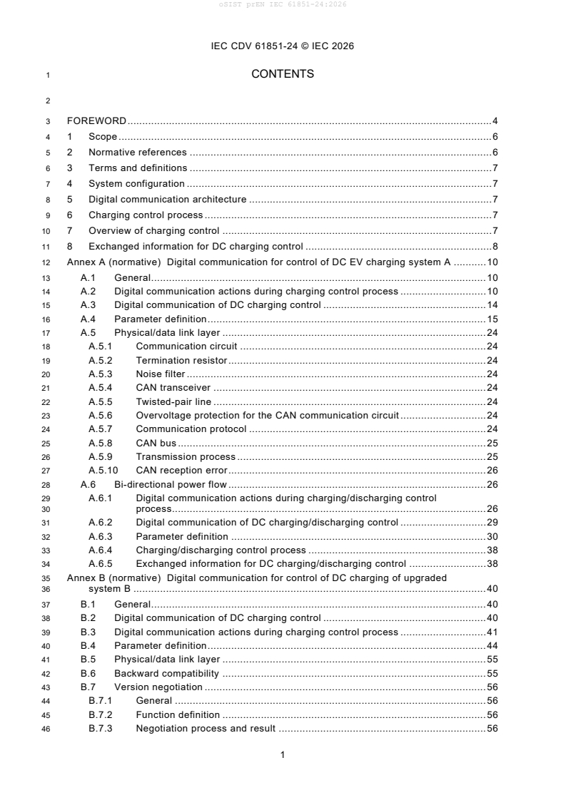
11 8 Exchanged information for DC charging control . 8
12 Annex A (normative) Digital communication for control of DC EV charging system A . 10
13 A.1 General . 10
14 A.2 Digital communication actions during charging control process . 10
15 A.3 Digital communication of DC charging control . 14
16 A.4 Parameter definition . 15
17 A.5 Physical/data link layer . 24
18 A.5.1 Communication circuit . 24
19 A.5.2 Termination resistor . 24
20 A.5.3 Noise filter . 24
21 A.5.4 CAN transceiver . 24
22 A.5.5 Twisted-pair line . 24
23 A.5.6 Overvoltage protection for the CAN communication circuit . 24
24 A.5.7 Communication protocol . 24
25 A.5.8 CAN bus . 25
26 A.5.9 Transmission process . 25
27 A.5.10 CAN reception error . 26
28 A.6 Bi-directional power flow . 26
29 A.6.1 Digital communication actions during charging/discharging control
30 process. 26
31 A.6.2 Digital communication of DC charging/discharging control . 29
32 A.6.3 Parameter definition . 30
33 A.6.4 Charging/discharging control process . 38
34 A.6.5 Exchanged information for DC charging/discharging control . 38
35 Annex B (normative) Digital communication for control of DC charging of upgraded
36 system B . 40
37 B.1 General . 40
38 B.2 Digital communication of DC charging control . 40
39 B.3 Digital communication actions during charging control process . 41
40 B.4 Parameter definition . 44
41 B.5 Physical/data link layer . 55
42 B.6 Backward compatibility . 55
43 B.7 Version negotiation . 56
44 B.7.1 General . 56
45 B.7.2 Function definition . 56
46 B.7.3 Negotiation process and result . 56
IEC CDV 61851-24 © IEC 2026
47 Annex C (normative) Digital communication for control of DC charging system C . 57
48 C.1 General . 57
49 C.2 Required exchange parameters . 57
50 Annex D (normative) Digital communication for control of DC charging system D . 59
51 D.1 General . 59
52 D.2 CAN-based digital communication . 59
53 D.2.1 Elements for digital communication . 59
54 D.2.2 Layered architecture . 60
55 D.2.3 Physical/data link layer . 61
56 D.2.4 Transport layer . 62
57 D.2.5 Application layer . 64
58 D.3 Two-wire Ethernet digital communication . 72
59 D.4 Digital Communication between EV /EVSE and adaptor . 72
60 D.5 Identification approach for two-wire Ethernet and CAN . 72
61 D.6 Charging/discharging control process . 72
62 Bibliography . 73
64 Figure 1 – Digital communication between a EVSE and an electric vehicle for control of
65 DC charging . 10
66 Figure A.1 – Sequence diagram of DC charging control communication for system A . 16
67 Figure A.2 – CAN communication circuit . 26
68 Figure A.3 – CAN bus . 27
69 Figure A.4 – Transmission cycle . 28
70 Figure A.5 – Sequence diagram of DC charging/discharging control communication for
71 system A . 32
72 Figure B.1 – Sequence diagram of DC charging control communication for upgraded
73 system B . 43
74 Figure B.2 – Sequence diagram of version negotiation for upgraded system B . 57
75 Figure D.1 – Layered structure for system D CAN-based communication protocol . 63
77 Table 1 – Exchanged information for DC charging control . 11
78 Table A.1 – Communication actions and parameters during DC charging control
79 process between system A station and vehicle (1 of 3) . 14
80 Table A.2 – Exchanged parameter during DC charging control process from vehicle to
81 system A station (1 of 4) . 19
82 Table A.3 – Exchanged parameter during DC charging control process from system A
83 station to vehicle (1 of 4) . 23
84 Table A.4 – The physical link layer specification for system A . 28
85 Table A.5 – Specification of data transmission . 28
86 Table A.6 – Communication actions and parameters during DC charging/discharging
87 control process between system A and vehicle . 30
88 Table A.7 – Exchanged parameter during DC charging/discharging control process
89 from vehicle to system A station (1 of 4) . 34
90 Table A.8 – Exchanged parameter during DC charging/discharging control process
91 from system A station to vehicle (1 of 3) . 38
92 Table A.9 – Exchanged information for DC charging/discharging control . 42
93 Table B.1 – Communication actions and exchanged information during DC charging
94 control process between upgraded system B EVSE and EV . 45
IEC CDV 61851-24 © IEC 2026
95 Table B.2 – Parameters in version negotiation . 48
96 Table B.3 – Public messages parameters in energy transfer process . 49
97 Table B.4 – Parameters in function negotiation . 50
98 Table B.5 – Parameters in parameter configuration . 51
99 Table B.6 – Parameters in authentication . 52
100 Table B.7 – Parameters in scheduled mode . 53
101 Table B.8 – Parameters in cable check . 54
102 Table B.9 – Parameters in power supply mode . 54
103 Table B.10 – Parameters in pre-charge and energy transfer . 55
104 Table B.11 – Message parameters in shutdown . 57
105 Table B.12 – Physical/data link layer specifications for system B . 58
106 Table C.1 – Required exchanged parameters for DC charging control for system C . 61
107 Table D.1 – Function module . 62
108 Table D.2 – Data link layer specifications for system D . 64
109 Table D.3 – Charger Protocol Version message . 65
110 Table D.4 – Vehicle Negotiation Result message . 65
111 Table D.5 – Format of unreliable message . 66
112 Table D.6 – Information Frame of Reliable Short Message . 66
113 Table D.7 – Acknowledge Frame of Reliable Short Message . 66
114 Table D.8 – Format of Information Frame of Long Message . 66
115 Table D.9 – Format of Control Frame of Long Message . 67
116 Table D.10 – Function Negotiation function module (FDC=1) . 67
117 Table D.11 – Parameter definition . 68
118 Table D.12 – Parameter configuration function module (FDC=1) . 69
119 Table D.13 – Parameter definition . 70
120 Table D.14 – Self-check function module (FDC=1) . 71
121 Table D.15 – Parameter definition . 72
122 Table D.16 – Energy Transfer in Charging Mode (FDC = 1) . 73
123 Table D.17 – Parameter definition . 74
IEC CDV 61851-24 © IEC 2026
126 INTERNATIONAL ELECTROTECHNICAL COMMISSION
127 ____________
129 ELECTRIC VEHICLE CONDUCTIVE CHARGING SYSTEM –
131 Part 24: Digital communication between a DC EV supply equipment and an
132 electric vehicle for control of DC charging
134 FOREWORD
135 1) The International Electrotechnical Commission (IEC) is a worldwide organization for standardization comprising
136 all national electrotechnical committees (IEC National Committees). The object of IEC is to promote international
137 co-operation on all questions concerning standardization in the electrical and electronic fields. To this end and
138 in addition to other activities, IEC publishes International Standards, Technical Specifications, Technical Reports,
139 Publicly Available Specifications (PAS) and Guides (hereafter referred to as “IEC Publication(s)”). Their
140 preparation is entrusted to technical committees; any IEC National Committee interested in the subject dealt with
141 may participate in this preparatory work. International, governmental and non-governmental organizations liaising
142 with the IEC also participate in this preparation. IEC collaborates closely with the International Organization for
143 Standardization (ISO) in accordance with conditions determined by agreement between the two organizations.
144 2) The formal decisions or agreements of IEC on technical matters express, as nearly as possible, an international
145 consensus of opinion on the relevant subjects since each technical committee has representation from all
146 interested IEC National Committees.
147 3) IEC Publications have the form of recommendations for international use and are accepted by IEC National
148 Committees in that sense. While all reasonable efforts are made to ensure that the technical content of IEC
149 Publications is accurate, IEC cannot be held responsible for the way in which they are used or for any
150 misinterpretation by any end user.
151 4) In order to promote international uniformity, IEC National Committees undertake to apply IEC Publications
152 transparently to the maximum extent possible in their national and regional publications. Any divergence between
153 any IEC Publication and the corresponding national or regional publication shall be clearly indicated in the latter.
154 5) IEC itself does not provide any attestation of conformity. Independent certification bodies provide conformity
155 assessment services and, in some areas, access to IEC marks of conformity. IEC is not responsible for any
156 services carried out by independent certification bodies.
157 6) All users should ensure that they have the latest edition of this publication.
158 7) No liability shall attach to IEC or its directors, employees, servants or agents including individual experts and
159 members of its technical committees and IEC National Committees for any personal injury, property damage or
160 other damage of any nature whatsoever, whether direct or indirect, or for costs (including legal fees) and
161 expenses arising out of the publication, use of, or reliance upon, this IEC Publication or any other IEC
162 Publications.
163 8) Attention is drawn to the Normative references cited in this publication. Use of the referenced publications is
164 indispensable for the correct application of this publication.
165 9) Attention is drawn to the possibility that some of the elements of this IEC Publication may be the subject of patent
166 rights. IEC shall not be held responsible for identifying any or all such patent rights.
167 International Standard IEC 61851-24 has been prepared by IEC technical committee 69:
168 Electrical power/energy transfer systems for electrically propelled road vehicles and industrial
169 trucks.
170 This second edition cancels and replaces the first edition published in 2014. This edition
171 constitutes a technical revision.
172 This edition includes the following significant technical changes with respect to the previous
173 edition:
174 a) Annex A and Annex B have been updated in line with IEC 61851-23:202X and relevant
175 standards;
176 The text of this document is based on the following documents:
CD Report on voting
69/XX/CD 69/XX/CC
IEC CDV 61851-24 © IEC 2026
178 Full information on the voting for the approval of this document can be found in the report on
179 voting indicated in the above table.
180 This publication has been drafted in accordance with the ISO/IEC Directives, Part 2.
181 A list of all parts in the IEC 61851 series, published under the general title Electric vehicle
182 conductive charging system, can be found on the IEC website.
183 The committee has decided that the contents of this publication will remain unchanged until the
184 stability date indicated on the IEC web site under "http://webstore.iec.ch" in the data related to
185 the specific publication. At this date, the publication will be
186 • reconfirmed,
187 • withdrawn,
188 • replaced by a revised edition, or
189 • amended.
191 The National Committees are requested to note that for this publication the stability date
192 is 2026.
193 THIS TEXT IS INCLUDED FOR THE INFORMATION OF THE NATIONAL COMMITTEES AND WILL BE DELETED
194 AT THE PUBLICATION STAGE.
IEC CDV 61851-24 © IEC 2026
196 ELECTRIC VEHICLE CONDUCTIVE CHARGING SYSTEM –
198 Part 24: Digital communication between a DC EV supply equipment and an
199 electric vehicle for control of DC charging
202 1 Scope
203 This part of IEC 61851, together with IEC 61851-23, applies to digital communication between
204 a EVSE and an electric road vehicle (EV) for control of conductive DC power transfer, with a
205 rated supply voltage up to 1 000 V AC or up to 1 500 V DC and a rated output voltage up to 1
206 500 V DC.
207 This document also applies to digital communication between the DC EV charging/discharging
208 station and the EV for system A, as specified in Annex A.
209 The EV charging mode is mode 4, according to IEC 61851-23.
210 Annex A, Annex B, and Annex C give descriptions of digital communications for control of DC
211 charging specific to DC EV charging systems A, B and C as defined in IEC 61851-23.
212 2 Normative references
213 The following documents are referred to in the text in such a way that some or all of their content
214 constitutes requirements of this document. For dated references, only the edition cited applies.
215 For undated references, the latest edition of the referenced document (including any
216 amendments) applies.
217 IEC 61851-23:202X, Electric vehicle conductive charging system – Part 23: DC electric vehicle
218 supply equipment
219 ISO TR 8713, Electric propelled road vehicles – Vocabulary
220 ISO 11898-1:2015, Road vehicles – Controller area network (CAN) – Part 1: Data link layer and
221 physical signaling
222 ISO 11898-2:2016, Road vehicles – Controller area network (CAN) – Part 2: High-speed
223 medium access unit
224 ISO 15118-2:2014, Road vehicles – Vehicle to grid communication interface – Part 2: Network
225 and application protocol requirements
226 ISO 15118-20:2022, Road vehicles – Vehicle to grid communication interface – Part 20: 2nd
227 generation network layer and application layer requirements
228 ISO 15118-20:202X AMD1, Road vehicles – Vehicle to grid communication interface – Part 20:
229 2nd generation network layer and application layer requirements AMENDMENT 1: AC DER
230 service, MCS service, and improved security concept
231 ISO 15118-202:2022, Road vehicles – Vehicle to grid communication interface – Part 202:
232 Extensible SECC Discovery Protocol and Event Notification Protocol
233 DIN TS 70121:2024, Electromobility – Digital communication between a DC EV charging station
234 and an electric vehicle for control of DC charging in the combined charging system
IEC CDV 61851-24 © IEC 2026
235 3 Terms and definitions
236 For the purposes of this document, the terms and definitions given in ISO TR 8713 and the
237 following apply.
239 ISO and IEC maintain terminological databases for use in standardization at the following
240 addresses:
242 IEC Electropedia: available at http://www.electropedia.org/
243 ISO Online browsing platform: available at http://www.iso.org/obp
244 This clause of IEC 61851-23:202X is applicable except as follows:
245 Addition:
246 3.1
247 parameter
248 single piece of information relevant to charging control, and that is exchanged between a EVSE
249 and an EV using a form of digital communication
250 3.2
251 signal
252 data element that is communicated between a EVSE and an EV using any means other than
253 digital communication
254 4 System configuration
255 The system configuration shall be in accordance with GG.2(TBD) of IEC 61851-23:202X.
256 5 Digital communication architecture
257 In this document, two digital communication architectures are used:
258 – based on CAN using a dedicated data communication circuit; CAN protocol is given in
259 ISO 11898-1. Refer to Annex A and Annex B for specific implementation details.
260 – based on Homeplug® Green PHY™ (see IEEE 1901) over the control pilot line; refer to
261 Annex C for specific implementation details.
262 6 Charging control process
263 H.3 of IEC 61851-23:202X provides general information on the charging process and the state
264 of EVSE.
265 Specific requirements of charging process are given in A.4 and A.6.3 for system A, B.4 for
266 system B, and C.3 for system C in IEC 61851-23:202X respectively.
267 7 Overview of charging control
268 The digital communication of DC charging control covered by this document is as shown in
269 Figure 1, identifying the SECC (supply equipment communication controller) and EVCC (EV
270 communication controller), as defined in IEC 61851-23. This document does not cover the
Homeplug® and Green PHY™ are examples of suitable products available commercially. This information isgivenfor
the convenience of users of this document and does not constitute an endorsement by IEC of these products.
IEC CDV 61851-24 © IEC 2026
271 control protocol internal to the EVSE, nor the vehicle, such as power control protocol for AC/DC
272 inverter of EVSE and battery management control in the vehicle.
EV supply equipment EV
vehicle vehicle
connector inlet
Digital communication Digital communication
SECC EVCC
interface interface
IEC 61851-24
275 Figure 1 – Digital communication between a EVSE and an electric vehicle for control of
276 DC charging
277 8 Exchanged information for DC charging control
278 This clause describes information which shall be exchanged between a EVSE and a vehicle
279 during the charging process according to IEC 61851-23. The information in Table 1 is common
280 to all systems described in Annex A, Annex B and Annex C. Each information listed in Table 1
281 is defined as a parameter in each annex. Each system can have additional parameters, and
282 these parameters are defined in each annex.
283 Table 1 – Exchanged information for DC charging control
Relevant
requirement
No. Information Description
in IEC 61851-23:
202X
Current request for the controlled Exchange of current value requested by
a-1
current charging (CCC) system EV
6.3.1.7
Voltage request for the controlled Exchange of voltage value requested by
a-2
voltage charging (CVC) system EV
Exchange of maximum rated voltage value 6.3.1.7
a-3 Maximum rated voltage of EVSE
of EVSE 6.3.1.10
Exchange of maximum rated current value 6.3.1.7
a-4 Maximum rated current of EVSE
of EVSE 6.3.1.10
Exchange of software version of a
b-1 Communication protocol
charging system
Exchange of maximum voltage limit value 6.3.1.10
b-2 Maximum voltage limit of EV
of vehicle. 6.3.1.12
EV minimum current limit, only for
b-3 the controlled voltage charging Under consideration
(CVC) system
Exchange information about available
Implementation of optional control 6.3.1.10
b-4 optional function, such as high current
function 6.3.2.8
control and dynamic control.
Exchange of the result of insulation check
before charging
c Insulation check result 6. 3.1.11
- If insulation check fails, a signal is sent
that charging is not allowed.
Exchange of information on short circuit
d Short circuit test before charging 6.3.1.14
test before charging
IEC CDV 61851-24 © IEC 2026
Relevant
requirement
No. Information Description
in IEC 61851-23:
202X
Exchange of information on charge stop 6.3.1.15
e Charging stopped by user
command by the user of EVSE
Exchange of EV supply equipment real
EV supply equipment real time time available load current for demand 6.3.2.8
f
available load current (optional) management. Required for system
providing that function.
Detection of loss of digital communication
- If a receiver does not get information
g Loss of digital communication 6.3.1.5
expected to receive within time out period,
it is considered as loss of digital
communication.
Notification of zero current confirmed
- Station informs EV that low current
h-1 Zero current confirmed
condition has been met (to allow the
6.3.1.18
opening and welding check of EV
G.3.4
contactors by EV)
Exchange of information on the whole
h-2 Welding detection
process of welding detection
Termination of the charging process not
i-1 Normal shutdown 6.3.1.18.2
caused by a failure
Termination of the charging process
i-2 Error shutdown 6.3.1.18.3
caused by a failure
IEC CDV 61851-24 © IEC 2026
284 Annex A
285 (normative)
287 Digital communication for control
288 of DC EV charging system A
290 A.1 General
291 This annex shows the specification of digital communication for control of the EVSE of system
292 A (in this annex, referred to as "System A station" or "station") as specified in Annex A of IEC
293 61851-23:20. More detailed information on System A is defined in IEEE 2030.1.1.
294 This annex is also applicable to the DC EV charging/discharging station of system A.
295 NOTE Technical Specifications of CHAdeMO 2.0.1, Amendment 1 2020, provides additional information on system
296 A. Available at https://www.chademo.com.
297 A.2 Digital communication actions during charging control process
298 The communication actions and parameters according to the charging control process as
299 defined in Table A.15 of IEC 61851-23:20 are shown in Table A.1.
IEC CDV 61851-24 © IEC 2026
300 Table A.1 – Communication actions and parameters during DC charging
301 control process between system A station and vehicle (1 of 3)
Charging Parameter
Digital
a
control State
High level action at system level
communication action
From EVSE From vehicle
stage
DC-A Vehicle unconnected None N/A N/A
DC-B1 Connector plugged in None N/A N/A
Wake up of DCCCF and VCCF None None (default CAN)
DC-B1
Preparation for digital
Communication data initialization (default CAN) (default CAN)
communication
– Control protocol number
– Control protocol number – Total capacity of battery
– Available output voltage – Maximum battery voltage
– Available output current – Maximum charging time
Communication established,
– Battery incompatibility – Target battery voltage
DC-B1→ Exchange of charging control
parameters exchanged, and
parameters
DC-B2
– Energizing state – Vehicle charging enabled
compatibility checked
– Identifier of welding detection – Minimum charge current
– Threshold voltage – Estimated charging time
– Charging stop control – Vehicle status
– Charged rate
DC-B2 Notification of state of
Connector latched – Energizing state None
→DC-B3
charging progress
Insulation resistance check for DC
– Charging system error
DC-B3 None None
power line
Pre-charge (depending on the system
DC-B3 N/A N/A N/A
architecture)
Initialization
Charge
Handshaking
preparation
IEC CDV 61851-24 © IEC 2026
303 Table A.1 (2 of 3)
Parameter
Charging
Digital
a
control State
High level action at system level
communication action
From EVSE From vehicle
stage
DC-C or Notification of vehicle main
Vehicle side contactors closed None – Vehicle status
DC-D contactor closed status
– Station status
– Output voltage
– Output current – Charging current request
DC-C or Notification of request value of
Charging by current demand (for CCC) – Remaining charging time – Charging system error
DC-D charging current (or voltage)
– Station error – Parking status of the vehicle
– Charging system error
– Charging stop control
DC-C or
Charging by voltage demand (for CVC) N/A N/A N/A
DC-D
– Station status
DC-C,(D)
Request of energy transfer – Charging stop control
- Vehicle charging enabled
Current suppression
→DC-B’1 shut-off – Output voltage
– Output current
Notification of energy transfer – Station status
DC-B’1 Zero current confirmed
shut-off – Charging system error
DC-B’1→
Welding detection (by vehicle) None None
DC-B’2
DC-B’2 Vehicle side contactors open None None – Vehicle status
- Output voltage
DC-B’2 DC power line voltage verification Notification of present voltage None
- Energizing state
Notification of connector
DC-B’3 Connector unlatched None None
unlatch status
Terminate the digital
DC-B’4 End of charge at communication level None None
communication
DC-A Connector unplugged N/A N/A
Shutdown (case 1) Energy transfer
IEC CDV 61851-24 © IEC 2026
305 Table A.1 (3 of 3)
Parameter
Charging
Digital
a
control State
High level action at system level
communication action
stage
From EVSE From vehicle
– Station status
Notification of energy transfer
DC-B’1 Zero current confirmed
shut-off
– Charging system error
DC-B’1→
Welding detection (by vehicle) None None
DC-B’2
DC-B’2 Vehicle side contactors open None None - Vehicle status
- Output voltage
DC-B’2 DC power line voltage verification Notification of present voltage None
- Energizing state
Notification of connector
DC-B’3-1 Connector remain latched None None
unlatch status
Terminate the digital
DC-B’4-1 End of charge at communication level None None
communication
DC-B’4-2 Connector unlatched or remain latched N/A N/A
DC-A or Connector unplugged or remain
N/A N/A
DC-B1 plugged in
a
The order of actions does not refer to the procedure of charging control process.
Shutdown (case 2)
IEC CDV 61851-24 © IEC 2026
308 A.3 Digital communication of DC charging control
309 The parameters for digital communication of DC charging control shall be exchanged according
310 to the sequence diagram as shown in Figure A.1.
312 NOTE For symbols, see Table AA.1 of IEC 61851-23: 20.
313 Figure A.1 – Sequence diagram of DC charging control communication for system A
IEC CDV 61851-24 © IEC 2026
314 A.4 Parameter definition
315 The definition of parameters during DC charging control process are shown in Table A.2 and
316 Table A.3. Table A.2 and Table A.3 include the mandatory parameters and the optional
317 parameters. The optional parameters are applied to the optional charging functions, such as
318 dynamic control (see AA.7 of IEC 61851-23:20) and charging with thermal management
319 system (see A.9 of IEC 61851-23:20). The optional charging functions may be used when the
320 station and the vehicle confirm the availability, specification and compatibility of functions by
321 exchanging the optional parameters each other.
IEC CDV 61851-24 © IEC 2026
322 Table A.2 – Exchanged parameter during DC charging control process from vehicle to system A station (1 of 4)
CAN Signed
Period Item in Status
ID DLC Byte Bit or Unit LSB Initial Min Max
Parameter Content
(ms) Table1 flag
(H') Unsigned
The minimum current value to
0 0-7 Minimum charging current U A 1 0 0 254 a-1 -
conduct charging
1-3 0-7 - - - - - - - - - -
The maximum voltage value at the
4 0-7
vehicle inlet terminals, at which the
Maximum battery voltage U V 1 0 1 200 b-2 -
station stops charging to protect the
100 100 8
5 0-7
vehicle battery
Fixed value for charging rate
Constant of charging rate indication, which is the maximum
-
6 0-7 U - 1 100 0 255 b-2
indication charging rate (100 %) of vehicle
battery
7 0-7
- - - - - - - - - -
0 0-7 - - - - - - - - - -
Maximum charging time Maximum charging time permitted by
1 0-7 U s 10 0 0 2 540 b-2 -
(set by 10 s) EV, set by 10 s
Maximum charging time Maximum charging time permitted by
2 0-7 U min 1 0 0 255 b-2 -
(set by 1 min) EV, set by minute
Estimated charging time Estimated remaining time before the
3 0-7 U min 1 0 254 b-2 -
101 100 8
(set by 1 min) end of charging calculated by EV
4 0-7 - - - - - - - - - -
6 553,
0-7 Rated capacity of battery Rated capacity of battery U kWh 0,1 0 b-2 -
7 0-7 - - - - - - - - - -
IEC CDV 61851-24 © IEC 2026
324 Table A.2 (2 of 4)
Signed
ID Period Item in Status
DLC Byte Bit or Unit LSB Initial Min Max
Parameter Content
(H') (ms) Table 1 flag
Unsigned
Software version of control sequence
0 0-7 Control protocol number U - 1 0 255 b-1 -
to which EV corresponds
Targeted charging voltage at the
1 0-7
Target battery voltage vehicle inlet terminals U V 1 0 1 200 b-2 -
2 0-7
Current value requested by EV
-
3 0-7 Charging current request U A 1 0 0 200 a-1
during charging
Status flag indicating whether or not
0: normal
the vehicle battery voltage exceeds
4 0 Battery overvoltage - - 1 0 0 1 i-2
1: fault
the maximum limit specified by EV
Status flag indicating whether or not
0: normal
1 Battery undervoltage the vehicle battery voltage is less - - 1 0 0 1 i-2
102 100 8 1: fault
than the lower limit specified by EV
Status flag indicating whether or not
0: normal
2 Battery current deviation error the output current deviates from EV - - 1 0 0 1 i-2
1: fault
requested current
Status flag indicating whether or not
0: normal
3 High battery temperature the temperature of vehicle battery - - 1 0 0 1 i-2
1: fault
exceeds the maximum limit
Status flag indicating whether or not
the vehicle battery voltage deviates 0: normal
4 Battery voltage deviation error - - 1 0 0 1 i-2
from the output voltage measured by 1: fault
the station
5-7 - - - - - - - - - -
IEC CDV 61851-24 © IEC 2026
326 Table A.2 (3 of 4)
Item in
Signed
ID Period
DLC Byte Bit or Unit LSB Initial Min Max Table
Parameter Content Status flag
(H') (ms)
Unsigned
Status flag indicating charge 0: disabled
5 0 Vehicle charging enabled - - 1 0 0 1 i-1
permission status of EV 1: enabled
Status flag indicating the 0: vehicle in
Parking status of the parking status of the vehicle parking position
1 - - 1 0 0 1 i-1
vehicle 1: vehicle not in
parking position
Status flag indicating a
0: normal
2 Charging system error malfunction caused by EV or the - - 1 0 0 1 i-2
1: fault
station, and detected by EV
Status flag indicating the EV 0: EV contactor
contactor status closed or during
102 100 8
welding detection
3 Vehicle status - - 1 1 0 1 h-2
1: EV contactor
open or welding
detection finished
Status flag indicating the
Normal stop request 0: no request
4 request of EV to stop charging - - 1 0 0 1 i-1
before charging 1: request to stop
control
5-7 - - - - - - - - - -
Charging rate of battery
6 0-7 Charging rate U % 1 0 100 a-1 -
7 0-7 - - - - - - - - - -
IEC CDV 61851-24 © IEC 2026
328 Table A.2 (4 of 4)
Optional parameters
Signed
Peri
Item in
ID
od DLC Byte Bit or Unit LSB Initial Min Max
Parameter Content Status flag
(H') Table 1
(ms) Unsigned
The minimum voltage value at -
the vehicle inlet terminals, at
Minimum battery
100 100 8 0-7 which the station stops U V 1 0 1 200 b-2
voltage
discharging to protect the vehicle
battery.
0: Incompatible
Flag indicating vehicle that is
0 Dynamic control - 1 0 0 1
compatible with dynamic control.
1: Compatible
Flag indicating vehicle that is
0: Incompatible
1 High current control compatible with high current - 1 0 0 1
1: Compatible
control.
Flag indicating vehicle that is
0: Incompatible
2 High voltage control compatible with high voltage - 1 0 0 1
1: compatible
110 100 8
control.
- - -
2-7 - - - - - - -
Current value that vehicle -
Request charging
1-2 0-7 requests the station during U A 1 0 0 1 023 a-1
current (extended)
charging.
- - -
3-7 0-7 - - - - - - -
Number assigned for each EV
EV manufacturer
0 0-7 manufacturer using the option - 1 0 255 -
code
code.
700 100 8
Data area exchanged between EV
supply equipment and EV for
1-7 0-7 Option code - - - - - - -
specific control or function
defined by the EV manufacturer.
Key
DLC: Data length code
U: Unsigned
LSB: Least significant bit
IEC CDV 61851-24 © IEC 2026
330 Table A.3 – Exchanged parameter during DC charging control process from system A station to vehicle (1 of 4)
Item
Signed
ID Period in
DLC Byte Bit or Unit LSB Initial Min Max Status flag
Parameter Content
(H') (ms)
Table
Unsigned
0: not supporting
vehicle welding
Identifier indicating whether or detection
Identifier of welding
0 0-7 not the station deals with EV - - 1 0 255 h-2 1 or more:
detection
contactor welding detection supporting
vehicle welding
detection
1 0-7 Maximum output voltage value
Available output voltage at the vehicle connector U V 1 0 1 200 a-3 -
108 100 8
2 0-7
terminals
Maximum output curre
...