

prEN 50130-4:2026
(Main)Alarm systems - Part 4: Electromagnetic compatibility - Immunity requirements
- Abstract
This document specifies immunity requirements for electromagnetic compatibility (EMC). It applies to components of the following safety and security systems intended for use in residential, commercial, light industrial and industrial environments: — access control systems, for security applications; — alarm transmission systems ; — video surveillance systems, for security applications; — fire detection and fire alarm systems; — hold-up alarm systems; — intruder alarm systems; — social alarm systems. The document applies to indoor and outdoor applications of fixed, movable and portable equipment.
- Status
- Not Published
- Publication Date
- 23-Sep-2027
- Technical Committee
- CLC/TC 79 - Alarm systems
- Drafting Committee
- CLC/TC 79/WG 09 - Environmental testing
- Current Stage
- 4060 - Enquiry results established and sent to TC, SR, BTTF - Enquiry
- Start Date
- 21-Aug-2026
- Due Date
- 04-Sep-2026
- Completion Date
- 21-Aug-2026

prEN 50130-4:2026 is a draft European Standard from CLC on electromagnetic compatibility (EMC) immunity for alarm-system components. It specifies how equipment used in access control, alarm transmission, video surveillance, fire detection and fire alarm, hold-up alarm, intruder alarm, and social alarm systems is tested for immunity in residential, commercial, light industrial, and industrial environments. It is written for manufacturers, test laboratories, and system specifiers who need a common immunity test basis for fixed, movable, and portable equipment.
What does prEN 50130-4:2026 specify?
prEN 50130-4:2026 specifies immunity requirements for EMC and the test approach used to check them. The standard covers indoor and outdoor applications of the listed alarm and security system components, so the same immunity approach is used across installation types.
The document is organized in a practical test-oriented way:
- Clause 1 states the scope.
- Clause 2 lists normative references.
- Clause 3 gives terms, definitions, and abbreviations.
- Clause 4 explains applicability.
- Clause 5 sets the test conditions.
- Clauses 6 to 11 cover the individual immunity phenomena.
- Annex A gives the criteria for operation as intended.
- Annex B gives guidance for that assessment.
- Annex ZZ links the standard to Directive 2014/30/EU.
| Annex | What it covers |
|---|---|
| Annex A | Criteria for operation as intended |
| Annex B | Guidance for assessing operation as intended |
| Annex ZZ | Relationship to Directive 2014/30/EU |
What are the key requirements of prEN 50130-4:2026?
General test approach and setup
prEN 50130-4:2026 treats the immunity checks as separate tests, and each test has to meet its own compliance criteria. If several tests are run on one sample, the order is optional, but the final assessment has to show the equipment still works as intended after the last test.
Clause 4 and Clause 5 make the setup requirements very practical:
- the EUT has to be configured as it would be in service, with relevant power, monitoring, loading, and auxiliary equipment connected;
- enough inputs and outputs have to be exercised to cover the different types of interfaces;
- cable type, length, termination, and port identification have to be recorded;
- if the product manual calls for external protection measures, the tests are done with those measures in place.
This matters because the immunity result should reflect the real installation, not an artificial lab-only setup.
Environmental and operating conditions
prEN 50130-4:2026 uses the standard atmospheric conditions from EN 60068-1 unless a basic EMC standard or the test procedure says otherwise. Each test is run at one set of parameters and at rated supply voltage, unless the document states something different.
The EUT has to be monitored during testing so that status changes, outputs, or alarm states can be detected. If the test makes the EUT dangerous or unsafe, the EUT is treated as having failed.
Performance criteria
Clause 5 separates performance criteria into two groups:
- continuous phenomena - radiated electromagnetic fields and conducted disturbances induced by electromagnetic fields;
- transient phenomena - supply dips and interruptions, electrostatic discharge, fast transient bursts, and slow high energy voltage surge.
For continuous phenomena, the EUT must not make an unintentional change of operating mode, and critical stored data should not change unintentionally. For transient phenomena, the same principle applies after the test: the EUT must still operate as intended, and Annex A is used to check that.
A useful practical point is that temporary deterioration of a video picture can be acceptable if the threat can still be detected. That matters for video surveillance equipment where a brief degradation is not the same as loss of the security function.
Clauses 6 to 11: the immunity tests
Clause 6 covers mains supply voltage dips and short interruptions on AC mains ports. Temporary loss of function can be acceptable during a full interruption if the EUT recovers without operator intervention, with no damage, malfunction, or unintended status change.
Clause 7 covers electrostatic discharge. Contact, air, direct, and indirect discharges are applied according to the installation and accessibility of surfaces. Brief indicator flicker is acceptable if it does not leave a residual change or output change.
Clause 8 covers radiated electromagnetic fields. The test includes amplitude-modulated fields, and some equipment, such as motion detectors and flame detectors, also gets pulse-modulated exposure. The cabling arrangement is especially important here, so the report has to document cable layout carefully.
Clause 9 covers conducted disturbances induced by electromagnetic fields on signal and supply lines. Motion detectors and flame detectors again receive additional pulse-modulated exposure. The clause also allows some ports to be excluded when the manufacturer limits connected cable length to a stated maximum.
Clause 10 covers fast transient bursts on AC mains, DC distribution networks, and signal lines. The clause states when the test is not required for short-cable ports, and it allows indicator flicker if the equipment does not show a residual change.
Clause 11 covers slow high energy voltage surge on mains, other supply and signal lines, and shielded lines. It sets different coupling cases for different line types and notes when ports with a documented cable-length limit can be excluded. If the coupling network affects operation, the EUT is checked again without the network for loss of data or damage.
Reporting and exceptions
Clause 5.4 requires a test report that contains enough information to reproduce the test. The report has to record the primary-function assessment method and result, and it has to explain any clause that was not applicable because of the nature of the EUT. That is important for audits, supplier acceptance, and conformity evidence.
What terms does prEN 50130-4:2026 define?
- EUT - Equipment Under Test: the equipment being checked for immunity.
- EMC - Electromagnetic Compatibility: the ability of equipment to operate without unacceptable disturbance in its electromagnetic environment.
- CW - Continuous Wave: an unmodulated carrier used as the basis for some field and conducted tests.
- CDN - Coupling Decoupling Network: the network used to inject conducted disturbances while separating the test setup from unwanted interference.
- VSS - Video Surveillance System: a system of camera, storage, monitoring, and associated transmission or control equipment.
- Primary function: the intended function of the safety or security component, such as detection, signalling, transmission, or access control.
- Response time: the time a system needs to react to a stimulus such as an alarm or fault.
- Signal line: a line used for signalling, communication, or power that is not meant to connect to an AC or DC distribution network.
Who uses prEN 50130-4:2026?
prEN 50130-4:2026 is used by manufacturers of alarm and security equipment, EMC test laboratories, certification and conformity teams, and system integrators. It is also relevant to quality managers and buyers who need to specify immunity expectations for products used in security, fire, and social alarm applications.
In practice, it is used when designing products, planning type tests, preparing test reports, and checking whether equipment still performs its primary function after immunity exposure. Annex ZZ also makes it relevant for anyone working with the EMC requirements of Directive 2014/30/EU.
What changed in prEN 50130-4:2026 from the previous edition?
prEN 50130-4:2026 supersedes EN 50130-4:2011 and EN 50130-4:2011/A1:2014. The foreword states these significant technical changes:
- the title was changed;
- the referenced base standards were updated to the latest versions;
- the test methods and/or requirements in Clauses 8 and 11 were changed.
The foreword also states that equipment meeting this edition is deemed to meet EN 50130-4:2011.
Which standards are used with prEN 50130-4:2026?
The standard relies on several basic EMC and environmental test standards:
- EN 60068-1 - gives the environmental test conditions.
- EN IEC 61000-4-2 - provides the ESD test method.
- EN IEC 61000-4-3 - provides the radiated RF field immunity test method.
- EN 61000-4-4 - provides the fast transient burst test method.
- EN 61000-4-5 - provides the surge test method.
- EN IEC 61000-4-6 - provides the conducted RF immunity test method.
- EN IEC 61000-4-11 - provides the voltage dip and short interruption test method.
The foreword and bibliography also point to companion product standards that cover other performance requirements for the same application areas:
- EN 50131
- EN 50134
- EN 50136
- EN 54
- EN 60839-11
- EN 62676
What does the prEN 50130-4:2026 document contain?
The standard contains the test philosophy, applicability rules, environmental and configuration requirements, and the pass/fail logic for EMC immunity testing. It also includes the specific test clauses for supply dips, electrostatic discharge, radiated fields, conducted disturbances, fast transients, and surge.
Annex A gives the practical criteria used to judge whether the primary function still works as intended. Annex B gives examples of how to assess that result for different alarm and security functions. Annex ZZ provides the legal traceability to Directive 2014/30/EU for EMC immunity.
Relations
- Effective Date
- 06-May-2025
Get Certified
Connect with accredited certification bodies for this standard

IMQ S.p.A. (Certification)
Italian electrical product certification.

SLG Prüf- und Zertifizierungs GmbH
German testing and certification body.

UL Solutions
Global safety science company with testing, inspection and certification.
Sponsored listings
Frequently Asked Questions
prEN 50130-4:2026 is a draft published by CLC. Its full title is "Alarm systems - Part 4: Electromagnetic compatibility - Immunity requirements". This standard covers: This document specifies immunity requirements for electromagnetic compatibility (EMC). It applies to components of the following safety and security systems intended for use in residential, commercial, light industrial and industrial environments: — access control systems, for security applications; — alarm transmission systems ; — video surveillance systems, for security applications; — fire detection and fire alarm systems; — hold-up alarm systems; — intruder alarm systems; — social alarm systems. The document applies to indoor and outdoor applications of fixed, movable and portable equipment.
This document specifies immunity requirements for electromagnetic compatibility (EMC). It applies to components of the following safety and security systems intended for use in residential, commercial, light industrial and industrial environments: — access control systems, for security applications; — alarm transmission systems ; — video surveillance systems, for security applications; — fire detection and fire alarm systems; — hold-up alarm systems; — intruder alarm systems; — social alarm systems. The document applies to indoor and outdoor applications of fixed, movable and portable equipment.
prEN 50130-4:2026 is classified under the following ICS (International Classification for Standards) categories: 13.320 - Alarm and warning systems; 29.020 - Electrical engineering in general. The ICS classification helps identify the subject area and facilitates finding related standards.
prEN 50130-4:2026 has the following relationships with other standards: It is inter standard links to EN 50130-4:2011/A1:2014. Understanding these relationships helps ensure you are using the most current and applicable version of the standard.
prEN 50130-4:2026 is associated with the following European legislation: EU Directives/Regulations: 2014/30/EU; Standardization Mandates: M/552. When a standard is cited in the Official Journal of the European Union, products manufactured in conformity with it benefit from a presumption of conformity with the essential requirements of the corresponding EU directive or regulation.
prEN 50130-4:2026 is available in PDF format for immediate download after purchase. The document can be added to your cart and obtained through the secure checkout process. Digital delivery ensures instant access to the complete standard document.
Standards Content (Sample)
SLOVENSKI STANDARD
01-julij-2026
Alarmni sistemi - 4. del: Elektromagnetna združljivost - Zahteve za odpornost
Alarm systems - Part 4: Electromagnetic compatibility - Immunity requirements
Alarmanlagen - Teil 4: Elektromagnetische Verträglichkeit - Anforderungen an die
Störfestigkeit
Systèmes d'alarme - Partie 4: Compatibilité électromagnétique - Exigences relatives à
l'immunité
Ta slovenski standard je istoveten z: prEN 50130-4:2026
ICS:
13.320 Alarmni in opozorilni sistemi Alarm and warning systems
33.100.20 Imunost Immunity
2003-01.Slovenski inštitut za standardizacijo. Razmnoževanje celote ali delov tega standarda ni dovoljeno.
EUROPEAN STANDARD DRAFT
prEN 50130-4
NORME EUROPÉENNE
EUROPÄISCHE NORM
May 2026
ICS 13.320; 29.020 Will supersede EN 50130-4:2011; EN 50130-
4:2011/A1:2014
English Version
Alarm systems - Part 4: Electromagnetic compatibility - Immunity
requirements
To be completed Alarmanlagen - Teil 4: Elektromagnetische Verträglichkeit -
Anforderungen an die Störfestigkeit
This draft European Standard is submitted to CENELEC members for enquiry.
Deadline for CENELEC: 2026-08-21.
It has been drawn up by CLC/TC 79.
If this draft becomes a European Standard, CENELEC members are bound to comply with the CEN/CENELEC Internal Regulations which
stipulate the conditions for giving this European Standard the status of a national standard without any alteration.
This draft European Standard was established by CENELEC in three official versions (English, French, German).
A version in any other language made by translation under the responsibility of a CENELEC member into its own language and notified to
the CEN-CENELEC Management Centre has the same status as the official versions.
CENELEC members are the national electrotechnical committees of Austria, Belgium, Bulgaria, Croatia, Cyprus, the Czech Republic,
Denmark, Estonia, Finland, France, Germany, Greece, Hungary, Iceland, Ireland, Italy, Latvia, Lithuania, Luxembourg, Malta, the
Netherlands, Norway, Poland, Portugal, Republic of North Macedonia, Romania, Serbia, Slovakia, Slovenia, Spain, Sweden, Switzerland,
Türkiye and the United Kingdom.
Recipients of this draft are invited to submit, with their comments, notification of any relevant patent rights of which they are aware and to
provide supporting documentation.
Warning : This document is not a European Standard. It is distributed for review and comments. It is subject to change without notice and
shall not be referred to as a European Standard.
European Committee for Electrotechnical Standardization
Comité Européen de Normalisation Electrotechnique
Europäisches Komitee für Elektrotechnische Normung
CEN-CENELEC Management Centre: Rue de la Science 23, B-1040 Brussels
© 2026 CENELEC All rights of exploitation in any form and by any means reserved worldwide for CENELEC Members.
Project: 81881 Ref. No. prEN 50130-4:2026 E
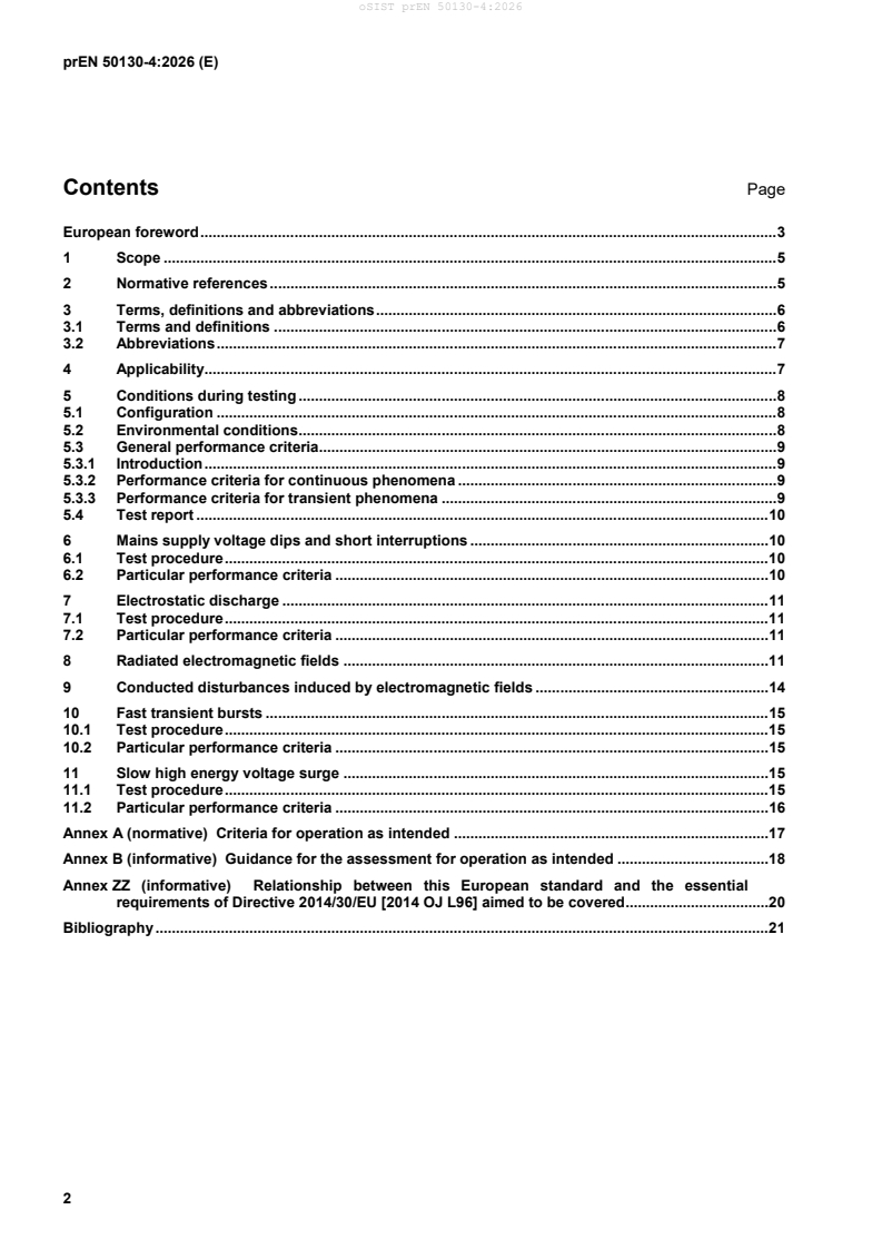
Contents Page
European foreword . 3
1 Scope . 5
2 Normative references . 5
3 Terms, definitions and abbreviations . 6
3.1 Terms and definitions . 6
3.2 Abbreviations . 7
4 Applicability. 7
5 Conditions during testing . 8
5.1 Configuration . 8
5.2 Environmental conditions . 8
5.3 General performance criteria. 9
5.3.1 Introduction . 9
5.3.2 Performance criteria for continuous phenomena . 9
5.3.3 Performance criteria for transient phenomena . 9
5.4 Test report . 10
6 Mains supply voltage dips and short interruptions . 10
6.1 Test procedure . 10
6.2 Particular performance criteria . 10
7 Electrostatic discharge . 11
7.1 Test procedure . 11
7.2 Particular performance criteria . 11
8 Radiated electromagnetic fields . 11
9 Conducted disturbances induced by electromagnetic fields . 14
10 Fast transient bursts . 15
10.1 Test procedure . 15
10.2 Particular performance criteria . 15
11 Slow high energy voltage surge . 15
11.1 Test procedure . 15
11.2 Particular performance criteria . 16
Annex A (normative) Criteria for operation as intended . 17
Annex B (informative) Guidance for the assessment for operation as intended . 18
Annex ZZ (informative) Relationship between this European standard and the essential
requirements of Directive 2014/30/EU [2014 OJ L96] aimed to be covered . 20
Bibliography . 21
European foreword
This document (prEN 50130-4:2026) has been prepared by CLC/TC 79 “Alarm systems”.
This document is currently submitted to the Enquiry.
The following dates are proposed:
• latest date by which the existence of this (doa) dav + 6 months
document has to be announced at national
level
• latest date by which this document has to be (dop) dav + 12 months
implemented at national level by publication of
an identical national standard or by
endorsement
• latest date by which the national standards (dow) dav + 36 months
conflicting with this document have to be (to be confirmed or
withdrawn modified when voting)
This document will supersede EN 50130-4:2011 and all of its amendments and corrigenda (if any).
a) the title was changed.
b) referenced based standards were updated to the latest versions;
c) changes were made to the test methods and/or requirements for Clauses 8 and 11;
Equipment meeting the requirements of this edition are deemed to meet the requirements of
EN 50130-4:2011 .
This document has been prepared under a standardization request addressed to CENELEC by the European
Commission. The Standing Committee of the EFTA States subsequently approves these requests for its
Member States.
For the relationship with EU Legislation, see informative Annex ZZ, which is an integral part of this document.
The following associated series of European documents are intended to give the other requirements (e.g.
performance requirements), which are applicable to the specific types of alarm systems:
— EN 50131, Alarm systems – Intrusion and hold-up systems;
— EN 50134, Alarm systems – Social alarm systems;
— EN 50136, Alarm systems – Alarm transmission systems and equipment;
— EN 54, Fire detection and fire alarm systems;
— EN 62676, Video surveillance systems for use in security applications;
As impacted by EN 50130-4:2011/A1:2014.
As impacted by EN 50130-4:2011/A1:2014.
— EN 60839-11, Alarm and electronic security systems - Part 11: Electronic access control systems.
1 Scope
This document specifies immunity requirements for electromagnetic compatibility (EMC). It applies to
components of the following safety and security systems intended for use in residential, commercial, light
industrial and industrial environments:
— access control systems, for security applications;
— alarm transmission systems ;
— video surveillance systems, for security applications;
— fire detection and fire alarm systems;
— hold-up alarm systems;
— intruder alarm systems;
— social alarm systems;
The document applies to indoor and outdoor applications of fixed, movable and portable equipment.
2 Normative references
The following documents are referred to in the text in such a way that some or all of their content constitutes
requirements of this document. For dated references, only the edition cited applies. For undated references,
the latest edition of the referenced document (including any amendments) applies.
EN 60068-1:2014, Environmental testing - Part 1: General and guidance (IEC 60068-1:2013)
EN IEC 61000-4-2:2025, Electromagnetic compatibility (EMC) - Part 4-2: Testing and measurement
techniques - Electrostatic discharge immunity test (IEC 61000-4-2:2025)
EN IEC 61000-4-3:2020, Electromagnetic compatibility (EMC) - Part 4-3 : Testing and measurement
techniques - Radiated, radio-frequency, electromagnetic field immunity test (IEC 61000-4-3:2020)
EN 61000-4-4:2012, Electromagnetic compatibility (EMC) - Part 4-4: Testing and measurement techniques -
Electrical fast transient/burst immunity test (IEC 61000-4-4:2012)
EN 61000-4-5:2014, Electromagnetic compatibility (EMC) - Part 4-5: Testing and measurement techniques -
Surge immunity test (IEC 61000-4-5:2014)
EN IEC 61000-4-6:2023, Electromagnetic compatibility (EMC) - Part 4-6: Testing and measurement
techniques - Immunity to conducted disturbances, induced by radio-frequency fields (IEC 61000-4-6:2023)
EN IEC 61000-4-11:2020, Electromagnetic compatibility (EMC) - Part 4-11: Testing and measurement
techniques - Voltage dips, short interruptions and voltage variations immunity tests for equipment with input
current up to 16 A per phase (IEC 61000-4-11:2020)
Apart from equipment which is part of a public communication network.
As impacted by EN 61000-4-5:2014/A1:2017 (IEC 61000-4-5:2014/A1:2017).
As impacted by EN IEC 61000-4-11:2020/AC:2022-10 (IEC 61000-4-11:2020/COR2:2022).
3 Terms, definitions and abbreviations
3.1 Terms and definitions
For the purposes of this document, the following terms and definitions apply.
ISO and IEC maintain terminology databases for use in standardization at the following addresses:
— ISO Online browsing platform: available at https://www.iso.org/obp/
— IEC Electropedia: available at https://www.electropedia.org/
3.1.1
access control system
system comprising all the constructional and organizational measures as well as those pertaining to the
equipment which are required for controlling access
3.1.2
alarm transmission system
Alarm Transmission Equipment and networks used to transfer information concerned with the state of one or
more alarm systems at a supervised premises to one or more annunciation equipment of one or more alarm
receiving centres
3.1.3
basic EMC standard
standard giving the description of, and test and measurement methods for an EMC phenomenon, along with
details of the test apparatus and test set-up, which can give guidance on the choice of severity but do not give
the prescribed limits or criteria for compliance
Note 1 to entry: Examples are standards of the EN 61000-4-x series
3.1.4
DC distribution network
local supply network in the infrastructure of a site or building intended for use by one or more different types of
equipment and providing power independent of the public mains network
Note 1 to entry: Connection to a remote local battery is not regarded as a DC distribution network, if such a link comprises
only power supply for a single piece of equipment.
3.1.5
European product performance standard
European Standard (EN) that specifies the product performance requirements, which can include EMC
requirements but is not limited to EMC requirements
Note 1 to entry: Examples are standards of the EN 54 series for fire alarm systems, and the EN 50131 series for intruder
alarm systems.
3.1.6
fire detection and fire alarm system
alarm system to detect the presence of fire in supervised premises and to raise the appropriate alarm
3.1.7
hold-up alarm system
alarm system providing the means for a user to deliberately generate a hold-up alarm condition
3.1.8
indication
annunciation of a condition in the alarm system by visual or audible means such as but not restricted to a LED
or a buzzer
3.1.9
intruder alarm system
alarm system to detect and indicate the presence, entry or attempted entry of an intruder into supervised
premises
3.1.10
primary function
function providing the intended purpose of the safety and security system components
Note 1 to entry: A safety and security system component can have more than one primary function. For example, the
primary functions of an intrusion detector include detection of a potential threat situation and transmitting the potential
threat situation
Note 2 to entry: Next to the primary function there might be other functions for example used for commissioning
3.1.11
response time
amount of time required for the system to react to a stimulus such as an alarm or fault
3.1.12
signal line
line used for signalling, communication or supplying power which is not intended to be connected to an AC or
DC distribution network
3.1.13
social alarm system
alarm system, providing facilities to summon assistance, for use by persons, who can be considered to be
living at risk
3.1.14
video surveillance system
system consisting of camera equipment, storage, monitoring and associated equipment for transmission and
controlling purposes which might be necessary for the surveillance of a defined secure area
3.2 Abbreviations
For the purposes of this document, the following abbreviations apply.
EUT Equipment Under Test
EMC Electromagnetic Compatibility
CW Continuous Wave, Carrier Wave
PCB Printed Circuit Board
VSS Video Surveillance System
CDN Coupling Decoupling Network
4 Applicability
The tests shall be carried out as single tests, as described in the later clauses, and the EUT shall meet the
criteria for compliance for each test. If several tests are made on a single example of the EUT, the sequence
of testing is optional, and it is permissible to substitute or omit intermediate assessments of the performance
of the EUT, provided that the assessment of the performance of the EUT is conducted after the last test.
NOTE If intermediate assessments of the performance of the EUT are substituted or omitted and a failure occurs, it
might not be possible to identify which test exposure caused the failure.
The tests and severities shall be the same for indoor and outdoor applications of fixed, movable and portable
equipment.
Where appropriate basic EMC standards exist, these are referred to in the relevant clauses. The content of
these basic EMC standards (i.e. the description of the test procedure, test apparatus and test set-up) are not
repeated here in full, however modifications or additional information needed for the particular application of
the tests are given in this document.
Where test clauses are not applicable due to the nature of the EUT, this shall be recorded in the test report,
along with a justification.
5 Conditions during testing
5.1 Configuration
The EUT shall be connected to a suitable power supply, monitoring and loading equipment. If the EUT is part
of a system, or can be connected to auxiliary equipment, then the EUT shall be tested while connected in a
configuration necessary for verifying its performance.
If the EUT has a large number of inputs/outputs, then a sufficient number shall be selected to simulate actual
operating conditions and to ensure that all the different types of inputs/outputs are covered. The connections
to inputs and outputs, which may be separated into different cables in a real installation, shall be separated
into different cables for the tests (e.g. detector loops).
Any external cables that are part of or attached to the EUT and or ancillary equipment shall be documented in
the test report. The minimum information provided shall be the cable type, length, termination and to which
port they are attached.
In cases where a EUT specification requires external protection devices or measures which are clearly
specified in the user's manual, the test requirements of this document shall be applied with the external
protection devices or measures in place.
The EUT shall be tested in an operation mode that permits examination of the criteria for compliance of this
document for each test. The configuration of the test sample shall be chosen to achieve maximum
susceptibility and shall be representative of its intended use. The configuration and mode of operation during
the tests shall be precisely noted in the test report.
During testing, the EUT shall be monitored to detect any change in its status, including any change in outputs,
which could be interpreted by associated equipment as a change in status.
Each test shall be carried out at one single set of parameters within the environmental conditions in 5.2 and at
the rated supply voltage of the EUT, unless otherwise indicated in this document.
If, as a result of the application of the tests defined in this document, the EUT becomes dangerous or unsafe,
it shall be deemed to have failed the test.
5.2 Environmental conditions
Unless otherwise indicated in the basic EMC standard or test procedure, the tests shall be carried out within
the following standard atmospheric conditions for measurements and tests, as specified in EN 60068-1:2014,
4.3:
— temperature: 15 °C to 35 °C;
— relative humidity: 25 % to 75 %;
— air pressure: 86 kPa to 106 kPa.
5.3 General performance criteria
5.3.1 Introduction
The performance criteria are used to take a decision on whether the EUT passes or fails immunity tests. For
the purpose of the present document two categories of performance criteria apply:
a) Performance criteria for continuous phenomena. Continuous phenomena are
— radiated electromagnetic fields;
— conducted disturbances induces by electromagnetic fields.
b) Performance criteria for transient phenomena. Transient phenomena are
— main supply voltage dips and short interruptions;
— electrostatic discharge;
— fast transient bursts;
— slow high energy voltage surge.
If, as a result of the application of the tests defined in this document, the EUT becomes dangerous or unsafe,
it shall be deemed to have failed the test.
5.3.2 Performance criteria for continuous phenomena
Unless otherwise indicated in this document, the criteria for compliance with tests for continuous phenomena
shall be:
— During application of the phenomena, the EUT shall not result in an unintentional change of the mode of
operation (e.g. signal alarm or fault).
— There should be no unintentional change of critical stored data as a result of the application of the
phenomena.
— For EUTs with the primary function of providing a video picture for monitoring a potential threat situation,
a temporary self-recovering deterioration of the picture is allowed, providing that the deterioration to the
video picture allows to detect a potential threat.
After application of the continuous phenomena the EUT shall operate as intended. This shall be verified by an
assessment of the expected performance of the primary function(s) according to Annex A.
NOTE If the EUT operates as intended after the application of the continuous phenomena it can be seen as proof
that no critical stored data were unintentional changed.
It is recommended to assess the performance of the primary function before application of the test to be able
to detect any deterioration of the primary function after the test.
5.3.3 Performance criteria for transient phenomena
Unless otherwise indicated in this document, the criteria for compliance with tests for transient phenomena
shall be:
— The application of the transient phenomena shall not result in the unintentional change of critical stored
data or an unintentional change of the mode of operation (e.g. signal alarm or fault) after the completion
of the test.
— After application of the transient phenomena the EUT shall operate as intended. This shall be verified by
an assessment of the expected performance of the primary function(s) according to Annex A.
NOTE If the EUT operates as intended after the application of the continuous phenomena it can be seen as proof
that no critical stored data were unintentional changed.
It is recommended to assess the performance of the primary function before application of the test to be able
to detect any deterioration of the primary function after the test.
5.4 Test report
The test report shall contain all the information necessary to reproduce the test. In particular,
EN IEC 61000-4-11:2020, Clause 10, EN IEC 61000-4-2:2025, Clause 9, EN IEC 61000-4-3:2020, Clause 10,
EN IEC 61000-4-6:2023, Clause 10, EN 61000-4-4:2012, Clause 10 and EN 61000-4-5:2014, Clause 10 shall
be applied. Additionally, the applied assessment method of the primary function and the result shall be
recorded in the test report.
6 Mains supply voltage dips and short interruptions
6.1 Test procedure
The test applies only to the port of the equipment intended to be connected to an A.C. mains supply.
The test apparatus and procedure shall be as described in EN IEC 61000-4-11:2020, Clauses 6, 7 and 8
The A.C. mains supply voltage shall be reduced from the nominal value by the following reductions for the
specified periods, in accordance with Table 1. The voltage changes shall occur at the zero crossings of the
voltage wave.
Table 1 — Mains supply voltage reductions and short interruptions – Test
Residual voltage 80 % 70 % 40 % 0 %
Duration of reduction (No. of periods)
250 25 10 250
(i.e. c
...