

IEC 62146-1:2026
(Main)Capacitors for high-voltage alternating current circuit-breakers - Part 1: General and grading capacitors
- Abstract
IEC 62146-1:2026 is available as IEC 62146-1:2026 RLV which contains the International Standard and its Redline version, showing all changes of the technical content compared to the previous edition.IEC 62146-1:2026 includes generalities of capacitors used on alternating current circuit-breakers and introduces specifications for grading capacitors. Regarding grading capacitors, their function is to control the voltage distribution across the individual interrupter units of a multi-break circuit-breaker.
This document applies to grading capacitors falling into one or both of the following categories for:
- mounting on air-insulated circuit-breakers.
- mounting on enclosed circuit-breakers (for example immersed in insulating gas, in oil, etc.).
The object of this document is:
- to define uniform rules regarding performances, testing and rating;
- to define specific safety rules;
- to provide a guidance for installation and operation.
This document does not apply to capacitors not directly associated with high-voltage alternating current circuit-breakers.
- Status
- Published
- Publication Date
- 22-Jul-2026
- Technical Committee
- TC 33 - Power capacitors and their applications
- Drafting Committee
- JMT 17A - TC 33/JMT 17A
- Current Stage
- PPUB - Publication issued
- Start Date
- 23-Jul-2026
- Completion Date
- 14-Aug-2026
Buy Documents
IEC 62146-1:2026 - Capacitors for high-voltage alternating current circuit-breakers - Part 1: General and grading capacitors
REDLINE IEC 62146-1:2026 RLV - Capacitors for high-voltage alternating current circuit-breakers - Part 1: General and grading capacitors
IEC 62146-1:2026 - Condensateurs pour disjoncteurs a courant alternatif haute tension - Partie 1: Généralités et condensateurs de répartition
IEC 62146-1:2026 is an International Standard from IEC for capacitors used on high-voltage alternating current circuit-breakers. It specifies the general rules and the grading capacitors used to control voltage distribution across interrupter units in a multi-break circuit-breaker.
The document is written for capacitor manufacturers, circuit-breaker manufacturers, test laboratories, purchasers, and maintenance teams that need to specify, test, install, or inspect these components. It gives a common basis for ratings, construction, testing, safety, marking, and service guidance.
What does IEC 62146-1:2026 specify?
IEC 62146-1:2026 specifies requirements for grading capacitors mounted on air-insulated circuit-breakers and on enclosed circuit-breakers such as units immersed in insulating gas or oil. It also gives generalities for capacitors used on alternating current circuit-breakers and points readers to IEC 62146-2:2023 for Transient Recovery Voltage (TRV) capacitors.
The standard’s stated aim is to set uniform rules for performance, testing, and rating, to define safety rules, and to give guidance for installation and operation. It excludes capacitors that are not directly associated with high-voltage alternating current circuit-breakers.
The document is organized into clauses for scope, references, terms, service conditions, ratings, design and construction, type tests, routine tests, a design aging test, installation and maintenance guidance, safety, and environmental aspects.
| Annex | What it covers |
|---|---|
| Annex A | Corrosion: service conditions and recommended test requirements |
| Annex B | Resonance frequency measurements, including time-domain and frequency-domain methods |
What are the key requirements of IEC 62146-1:2026?
IEC 62146-1:2026 focuses on how to rate, build, test, mark, and use grading capacitors so that they match the circuit-breaker they support. In practice, the standard ties the capacitor specification to the breaker design, the insulation environment, and the expected mechanical and electrical stresses.
Service conditions and ratings
Clause 5 aligns normal and special service conditions with IEC 62271-1, with additional points for capacitors. For outdoor use, the normal conditions follow the breaker standard; for immersed capacitors, the surrounding medium can be hotter than ambient air, and the manufacturer is expected to consider the internal operating temperature.
Altitude is treated as a design condition up to 1 000 m, and above that the external insulation withstand level is corrected by an altitude factor. For earthquakes, grading capacitors are treated as breaker accessories and are covered by the seismic qualification rules of IEC 62271-300. This matters because the capacitor rating is not chosen in isolation - it must fit the breaker, the installation site, and the expected environment.
Clause 6 bases the rated voltage of a grading capacitor on the circuit-breaker rated voltage, the number of interrupter units per pole, and the voltage grading factor F, standardized at 1.2. The rated insulation level is derived from the breaker withstand values, using the relevant grading factor and application case. The standard values for rated frequency are 50 Hz and 60 Hz.
Design, materials, and construction
Clause 7 sets the main construction rules. Capacitance tolerance is limited to ±5 % for capacitors for air-insulated circuit-breakers and ±3 % for capacitors in enclosed circuit-breakers. Losses are expressed as tangent of the loss angle (tan δ), and the acceptable loss values are agreed between manufacturer and purchaser.
Partial discharge limits are given for grading capacitors, with different limits for air-insulated and immersed service. The standard also requires grading capacitors to be installable in any direction, and it specifies a minimum mechanical bending load for the relevant mounting cases. This is important because the capacitor is both an electrical component and a structural part of the breaker assembly.
Clause 7 also requires the manufacturer to state the impregnation medium, to specify liquid quality when liquids are used, and to address liquid leakage, gas tightness, corrosion protection, marking, and creepage distance for outdoor capacitors. The nameplate information includes the manufacturer identity, type designation, serial number, rated voltage, rated frequency, rated capacitance and tolerance, test voltage, temperature range, filling quantity or pressure, fluid designation, and the IEC 62146-1 edition reference.
Type tests and design verification
Clause 8 describes type tests that prove the design before series production. These include dielectric tests, switching impulse testing for capacitors installed on breakers rated at 300 kV and above, lightning and chopped lightning impulse tests, low- and high-temperature voltage tests, radio interference voltage (RIV) testing, power-frequency withstand testing for lower rated voltages, short-circuit discharge testing, resonance frequency measurement, mechanical bending, tightness checks, and vibration testing.
The clause also requires clear specimen identification, traceable type-test reports, and repeated type testing after design changes unless the manufacturer shows the change does not affect the result. In practice, this is the clause that links the design drawing to the actual test sample and to the final test evidence.
Routine tests, aging, and operating guidance
Clause 9 requires routine tests on production units, including capacitance and tan δ measurement, power-frequency withstand testing, partial discharge testing, tightness testing where applicable, and final visual and dimensional checks. The acceptance criteria are tied to the measured capacitance change, the permitted loss angle, and the partial discharge limits.
Clause 10 gives an aging test with long-duration voltage stress at elevated temperature, followed by repeat routine checks. Clauses 11 to 13 provide guidance for transport, storage, unpacking, lifting, mounting, connections, operation, maintenance, safety precautions, and environmental aspects. These sections matter because field performance depends on handling and upkeep as much as on the initial test result.
What terms does IEC 62146-1:2026 define?
IEC 62146-1:2026 defines the technical terms used to specify the capacitor, its insulation system, and its test results. The definitions make the electrical and mechanical requirements readable across manufacturers and test houses.
- grading capacitor - a capacitor installed on a high-voltage circuit-breaker to control the voltage distribution across an individual interrupter unit.
- capacitor unit - an assembly of one or more capacitor elements in the same container with terminals brought out.
- rated capacitance of a capacitor - the capacitance value for which the capacitor is designed.
- rated insulation level - the set of test voltages the insulation is designed to withstand under specified conditions.
- voltage grading factor of a circuit-breaker (F) - the factor used to define standard rated voltages for the grading capacitor from the breaker voltage distribution.
- tangent of the loss angle of a capacitor (tan δ) - the ratio used to express capacitor losses at a specified voltage and frequency.
- resonance frequency - the frequency where the capacitor’s capacitance reactance equals its self-inductance reactance.
- Transient Recovery Voltage (TRV) - the breaker-related transient voltage for which IEC 62146-2:2023 provides the capacitor application.
Who uses IEC 62146-1:2026?
IEC 62146-1:2026 is used by capacitor manufacturers who design grading capacitors and need a testable specification. It is also used by circuit-breaker manufacturers and switchgear engineers who have to match the capacitor to the interrupter design, insulation level, and mechanical arrangement.
Testing laboratories use it to prepare specimens, run type tests and routine tests, and write the test reports. Purchasers and quality managers use it to state ratings, service conditions, and acceptance expectations in procurement and project documentation. Maintenance and field teams use it for installation, inspection, handling, and periodic condition checks.
What changed in IEC 62146-1:2026 from the previous edition?
IEC 62146-1:2026 is the second edition and replaces the first edition published in 2016. The stated technical changes are clause re-ordering, reworked sentences, and new type and special tests.
Which standards are used with IEC 62146-1:2026?
IEC 62146-1:2026 relies on a set of normative references for test methods, insulation coordination, fluids, and switchgear coordination.
| Standard | What it contributes |
|---|---|
| IEC 60060-1 | High-voltage test terminology and test requirements, including impulse waveforms |
| IEC 60068-2-17:2023 | Sealing tests used for tightness checks |
| IEC 60071-2:2023 | Insulation coordination guidance and altitude correction methods |
| IEC 60270:2025 | Partial discharge measurement method |
| IEC 60296 | Mineral insulating oils for electrical equipment |
| IEC 60567 | Gas sampling and analysis of mineral oils and other insulating liquids |
| IEC 60815 (all parts) | Creepage selection for polluted conditions |
| IEC 60867 | Unused synthetic aromatic hydrocarbon insulating liquids |
| IEC 61099 | Unused synthetic organic esters for electrical purposes |
| IEC 61462 | Composite hollow insulators and related test methods |
| IEC 62146-2:2023 | TRV capacitors, including the related application case |
| IEC 62155:2003 | Hollow ceramic and glass insulators used for electrical equipment |
| IEC 62271-1 | Common specifications for AC switchgear and controlgear |
| IEC 62271-100 | AC circuit-breakers |
| IEC 62271-203 | AC gas-insulated metal-enclosed switchgear |
| IEC 62271-205 | Compact switchgear assemblies above 52 kV |
| IEC 62271-300 | Seismic qualification of AC circuit-breakers |
| IEC 62770 | Unused natural esters for transformers and similar equipment |
| IEC 63012 | Unused modified or blended esters for electrotechnical applications |
What does the IEC 62146-1:2026 document contain?
IEC 62146-1:2026 contains rating rules, design limits, and a complete test structure for grading capacitors. It includes the stated limits for capacitance tolerance, partial discharge, losses, resonance frequency, bending load, tightness, and test voltages, plus the acceptance criteria for type tests, routine tests, and the aging test.
The document also contains example figures for dielectric type-test sequencing, routine test sequencing, reduced-scale model geometry, and resonance measurement arrangements. Table 1 gives the partial discharge test voltages and permissible levels, while Annex B explains both time-domain and frequency-domain methods for measuring resonance frequency.
Relations
- Effective Date
- 05-Sep-2023
- Effective Date
- 05-Sep-2023
Buy Documents
IEC 62146-1:2026 - Capacitors for high-voltage alternating current circuit-breakers - Part 1: General and grading capacitors
REDLINE IEC 62146-1:2026 RLV - Capacitors for high-voltage alternating current circuit-breakers - Part 1: General and grading capacitors
IEC 62146-1:2026 - Condensateurs pour disjoncteurs a courant alternatif haute tension - Partie 1: Généralités et condensateurs de répartition
Frequently Asked Questions
IEC 62146-1:2026 is a standard published by the International Electrotechnical Commission (IEC). Its full title is "Capacitors for high-voltage alternating current circuit-breakers - Part 1: General and grading capacitors". This standard covers: IEC 62146-1:2026 is available as IEC 62146-1:2026 RLV which contains the International Standard and its Redline version, showing all changes of the technical content compared to the previous edition.IEC 62146-1:2026 includes generalities of capacitors used on alternating current circuit-breakers and introduces specifications for grading capacitors. Regarding grading capacitors, their function is to control the voltage distribution across the individual interrupter units of a multi-break circuit-breaker. This document applies to grading capacitors falling into one or both of the following categories for: - mounting on air-insulated circuit-breakers. - mounting on enclosed circuit-breakers (for example immersed in insulating gas, in oil, etc.). The object of this document is: - to define uniform rules regarding performances, testing and rating; - to define specific safety rules; - to provide a guidance for installation and operation. This document does not apply to capacitors not directly associated with high-voltage alternating current circuit-breakers.
IEC 62146-1:2026 is available as IEC 62146-1:2026 RLV which contains the International Standard and its Redline version, showing all changes of the technical content compared to the previous edition.IEC 62146-1:2026 includes generalities of capacitors used on alternating current circuit-breakers and introduces specifications for grading capacitors. Regarding grading capacitors, their function is to control the voltage distribution across the individual interrupter units of a multi-break circuit-breaker. This document applies to grading capacitors falling into one or both of the following categories for: - mounting on air-insulated circuit-breakers. - mounting on enclosed circuit-breakers (for example immersed in insulating gas, in oil, etc.). The object of this document is: - to define uniform rules regarding performances, testing and rating; - to define specific safety rules; - to provide a guidance for installation and operation. This document does not apply to capacitors not directly associated with high-voltage alternating current circuit-breakers.
IEC 62146-1:2026 is classified under the following ICS (International Classification for Standards) categories: 31.060.01 - Capacitors in general; 31.060.70 - Power capacitors. The ICS classification helps identify the subject area and facilitates finding related standards.
IEC 62146-1:2026 has the following relationships with other standards: It is inter standard links to IEC 62146-1:2013/AMD1:2016, IEC 62146-1:2013. Understanding these relationships helps ensure you are using the most current and applicable version of the standard.
IEC 62146-1:2026 is available in PDF format for immediate download after purchase. The document can be added to your cart and obtained through the secure checkout process. Digital delivery ensures instant access to the complete standard document.
Standards Content (Sample)
IEC 62146-1 ®
Edition 2.0 2026-07
INTERNATIONAL
STANDARD
Capacitors for high-voltage alternating current circuit-breakers -
Part 1: General and grading capacitors
ICS 31.060.01; 31.060.70 ISBN 978-2-8327-1381-5
All rights reserved. Unless otherwise specified, no part of this publication may be reproduced or utilized in any form or
by any means, electronic or mechanical, including photocopying and microfilm, without permission in writing from either
IEC or IEC's member National Committee in the country of the requester. If you have any questions about IEC copyright
or have an enquiry about obtaining additional rights to this publication, please contact the address below or your local
IEC member National Committee for further information.
IEC Secretariat Tel.: +41 22 919 02 11
3, rue de Varembé info@iec.ch
CH-1211 Geneva 20 www.iec.ch
Switzerland
About the IEC
The International Electrotechnical Commission (IEC) is the leading global organization that prepares and publishes
International Standards for all electrical, electronic and related technologies.
About IEC publications
The technical content of IEC publications is kept under constant review by the IEC. Please make sure that you have the
latest edition, a corrigendum or an amendment might have been published.
IEC publications search - IEC Products & Services Portal - products.iec.ch
webstore.iec.ch/advsearchform Discover our powerful search engine and read freely all the
The advanced search enables to find IEC publications by a publications previews, graphical symbols and the glossary.
variety of criteria (reference number, text, technical With a subscription you will always have access to up to date
committee, …). It also gives information on projects, content tailored to your needs.
replaced and withdrawn publications.
Electropedia - www.electropedia.org
The world's leading online dictionary on electrotechnology,
IEC Just Published - webstore.iec.ch/justpublished
Stay up to date on all new IEC publications. Just Published containing more than 22 500 terminological entries in English
details all new publications released. Available online and and French, with equivalent terms in 25 additional languages.
once a month by email. Also known as the International Electrotechnical Vocabulary
(IEV) online.
IEC Customer Service Centre - webstore.iec.ch/csc
If you wish to give us your feedback on this publication or
need further assistance, please contact the Customer
Service Centre: sales@iec.ch.
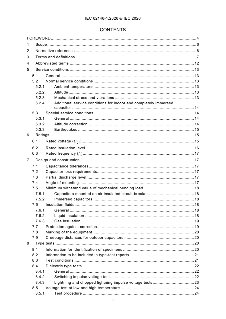
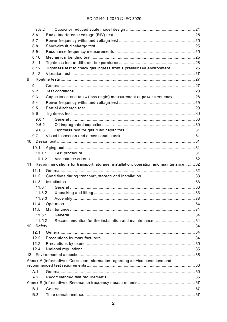
CONTENTS
FOREWORD . 4
1 Scope . 6
2 Normative references . 6
3 Terms and definitions . 7
4 Abbreviated terms . 12
5 Service conditions . 13
5.1 General . 13
5.2 Normal service conditions . 13
5.2.1 Ambient temperature . 13
5.2.2 Altitude . 13
5.2.3 Mechanical stress and vibrations . 13
5.2.4 Additional service conditions for indoor and completely immersed
capacitor . 14
5.3 Special service conditions . 14
5.3.1 General . 14
5.3.2 Altitude correction. 14
5.3.3 Earthquakes . 15
6 Ratings . 15
6.1 Rated voltage (U ) . 15
cr
6.2 Rated insulation level . 16
6.3 Rated frequency (f ) . 17
r
7 Design and construction . 17
7.1 Capacitance tolerances . 17
7.2 Capacitor loss requirements. 17
7.3 Partial discharge level . 17
7.4 Angle of mounting . 17
7.5 Minimum withstand value of mechanical bending load . 18
7.5.1 Capacitors mounted on air insulated circuit-breaker . 18
7.5.2 Immersed capacitors . 18
7.6 Insulation fluids . 18
7.6.1 General . 18
7.6.2 Liquid insulation . 18
7.6.3 Gas insulation . 19
7.7 Protection against corrosion . 19
7.8 Marking of the equipment . 20
7.9 Creepage distances for outdoor capacitors . 20
8 Type tests . 20
8.1 Information for identification of specimens . 20
8.2 Information to be included in type-test reports. 21
8.3 Test conditions . 21
8.4 Dielectric type tests . 22
8.4.1 General . 22
8.4.2 Switching impulse voltage test . 22
8.4.3 Lightning and chopped lightning impulse voltage tests . 23
8.5 Voltage test at low and high temperature . 24
8.5.1 Test procedure . 24
8.5.2 Capacitor reduced-scale model design . 24
8.6 Radio interference voltage (RIV) test . 25
8.7 Power frequency withstand voltage test . 25
8.8 Short-circuit discharge test . 25
8.9 Resonance frequency measurements . 25
8.10 Mechanical bending test . 25
8.11 Tightness test at different temperatures . 26
8.12 Tightness test to check gas ingress from a pressurised environment . 26
8.13 Vibration test . 27
9 Routine tests . 27
9.1 General . 27
9.2 Test conditions . 28
9.3 Capacitance and tan δ (loss angle) measurement at power frequency . 28
9.4 Power frequency withstand voltage test . 29
9.5 Partial discharge test . 29
9.6 Tightness test . 30
9.6.1 General . 30
9.6.2 Oil impregnated capacitor . 30
9.6.3 Tightness test for gas filled capacitors . 31
9.7 Visual inspection and dimensional check . 31
10 Design test . 31
10.1 Aging test . 31
10.1.1 Test procedure . 31
10.1.2 Acceptance criteria . 32
11 Recommendations for transport, storage, installation, operation and maintenance . 32
11.1 General . 32
11.2 Conditions during transport, storage and installation . 33
11.3 Installation . 33
11.3.1 General . 33
11.3.2 Unpacking and lifting . 33
11.3.3 Assembly . 33
11.4 Operation . 34
11.5 Maintenance . 34
11.5.1 General . 34
11.5.2 Recommendation for the installation and maintenance . 34
12 Safety . 34
12.1 General . 34
12.2 Precautions by manufacturers . 34
12.3 Precautions by users . 35
12.4 National regulations . 35
13 Environmental aspects . 35
Annex A (informative) Corrosion: Information regarding service conditions and
recommended test requirements . 36
A.1 General . 36
A.2 Recommended test requirements . 36
Annex B (informative) Resonance frequency measurements . 37
B.1 General . 37
B.2 Time domain method . 37
B.2.1 General . 37
B.2.2 Test procedure . 37
B.2.3 Measurement results . 38
B.3 Frequency domain method . 39
B.3.1 General . 39
B.3.2 Test setup . 39
B.3.3 Measurement results . 39
Bibliography . 41
Figure 1 – Factor m for the switching impulse withstand test . 15
Figure 2 – Example of a dielectric type test sequence . 22
Figure 3 – Reduced scale model capacitor element geometry . 24
Figure 4 – Example of an electrical routine test sequence . 28
Figure B.1 – Example of test setup for resonance frequency measurements in time
domain (see 8.9) . 37
Figure B.2 – Example of time domain voltage transient response to calculate
resonance frequency (see 8.9) . 38
Figure B.3 – Wiring diagram of the measuring circuit for the high-frequency response
(adapted from IEC 60358-2, Annex AA) . 39
Figure B.4 – Frequency response of a high voltage capacitor: Impedance magnitude
(blue, solid line) and phase (red, dashed line) . 40
Table 1 – Partial discharge test voltages and permissible levels for grading capacitors . 17
INTERNATIONAL ELECTROTECHNICAL COMMISSION
____________
Capacitors for high-voltage alternating current circuit-breakers -
Part 1: General and grading capacitors
FOREWORD
1) The International Electrotechnical Commission (IEC) is a worldwide organization for standardization comprising
all national electrotechnical committees (IEC National Committees). The object of IEC is to promote international
co-operation on all questions concerning standardization in the electrical and electronic fields. To this end and
in addition to other activities, IEC publishes International Standards, Technical Specifications, Technical Reports,
Publicly Available Specifications (PAS) and Guides (hereafter referred to as "IEC Publication(s)"). Their
preparation is entrusted to technical committees; any IEC National Committee interested in the subject dealt with
may participate in this preparatory work. International, governmental and non-governmental organizations liaising
with the IEC also participate in this preparation. IEC collaborates closely with the International Organization for
Standardization (ISO) in accordance with conditions determined by agreement between the two organizations.
2) The formal decisions or agreements of IEC on technical matters express, as nearly as possible, an international
consensus of opinion on the relevant subjects since each technical committee has representation from all
interested IEC National Committees.
3) IEC Publications have the form of recommendations for international use and are accepted by IEC National
Committees in that sense. While all reasonable efforts are made to ensure that the technical content of IEC
Publications is accurate, IEC cannot be held responsible for the way in which they are used or for any
misinterpretation by any end user.
4) In order to promote international uniformity, IEC National Committees undertake to apply IEC Publications
transparently to the maximum extent possible in their national and regional publications. Any divergence between
any IEC Publication and the corresponding national or regional publication shall be clearly indicated in the latter.
5) IEC itself does not provide any attestation of conformity. Independent certification bodies provide conformity
assessment services and, in some areas, access to IEC marks of conformity. IEC is not responsible for any
services carried out by independent certification bodies.
6) All users should ensure that they have the latest edition of this publication.
7) No liability shall attach to IEC or its directors, employees, servants or agents including individual experts and
members of its technical committees and IEC National Committees for any personal injury, property damage or
other damage of any nature whatsoever, whether direct or indirect, or for costs (including legal fees) and
expenses arising out of the publication, use of, or reliance upon, this IEC Publication or any other IEC
Publications.
8) Attention is drawn to the Normative references cited in this publication. Use of the referenced publications is
indispensable for the correct application of this publication.
9) IEC draws attention to the possibility that the implementation of this document may involve the use of (a)
patent(s). IEC takes no position concerning the evidence, validity or applicability of any claimed patent rights in
respect thereof. As of the date of publication of this document, IEC had not received notice of (a) patent(s), which
may be required to implement this document. However, implementers are cautioned that this may not represent
the latest information, which may be obtained from the patent database available at https://patents.iec.ch. IEC
shall not be held responsible for identifying any or all such patent rights.
IEC 62146-1 has been prepared by IEC technical committee 33: Power capacitors and their
applications. It is an International Standard.
This second edition cancels and replaces the first edition published in 2016. This edition
constitutes a technical revision.
This edition includes the following significant technical changes with respect to the previous
edition:
a) Clause re-ordering and reworked sentences;
b) New type and special tests.
The text of this International Standard is based on the following documents:
Draft Report on voting
33/746/FDIS 33/750/RVD
Full information on the voting for its approval can be found in the report on voting indicated in
the above table.
The language used for the development of this International Standard is English.
This document was drafted in accordance with ISO/IEC Directives, Part 2, and developed in
accordance with ISO/IEC Directives, Part 1 and ISO/IEC Directives, IEC Supplement, available
at www.iec.ch/members_experts/refdocs. The main document types developed by IEC are
described in greater detail at www.iec.ch/publications.
A list of all parts in the IEC 62146 series, published under the general title Capacitors for
high-voltage alternating current circuit-breakers, can be found on the IEC website.
Future documents in this series will carry the new general title as cited above. Titles of existing
documents in this series will be updated at the time of the next edition.
The committee has decided that the contents of this document will remain unchanged until the
stability date indicated on the IEC website under webstore.iec.ch in the data related to the
specific document. At this date, the document will be
– reconfirmed,
– withdrawn, or
– revised.
1 Scope
This part of IEC 62146 includes generalities of capacitors used on alternating current circuit-
breakers and introduces specifications for grading capacitors. Regarding grading capacitors,
their function is to control the voltage distribution across the individual interrupter units of a
multi-break circuit-breaker.
Capacitors can also be used in parallel to the interrupter unit on single break circuit-breakers
to modify the Transient Recovery Voltage (TRV). This TRV capacitor application is covered by
IEC 62146-2:2023.
Capacitors for high-voltage alternating circuit breakers are sub-components for the circuit-
breaker and are specified in accordance with the circuit-breaker specifications according to
IEC 62271-1, IEC 62271-100, and if applicable to IEC 62271-203.
This document applies to grading capacitors falling into one or both of the following categories
for:
− mounting on air-insulated circuit-breakers.
− mounting on enclosed circuit-breakers (for example immersed in insulating gas, in oil, etc.).
The testing for each of the above applications is in some cases different.
The object of this document is:
− to define uniform rules regarding performances, testing and rating;
− to define specific safety rules;
− to provide a guidance for installation and operation.
NOTE CIGRÉ TB-368 presents a study about the operating environment of voltage grading capacitors applied to
high-voltage circuit-breakers (see [2] ).
This document does not apply to capacitors not directly associated with high-voltage alternating
current circuit-breakers.
2 Normative references
The following documents are referred to in the text in such a way that some or all of their content
constitutes requirements of this document. For dated references, only the edition cited applies.
For undated references, the latest edition of the referenced document (including any
amendments) applies.
IEC 60060-1, High-voltage test techniques - Part 1: General terminology and test requirements
IEC 60068-2-17:2023, Environmental testing - Part 2-17: Tests - Test Q: Sealing
IEC 60071-2:2023, Insulation co-ordination - Part 2: Application guidelines
IEC 60270:2025, High-voltage test techniques - Charge-based measurement of partial
discharges
IEC 60296, Fluids for electrotechnical applications - Mineral insulating oils for electrical
equipment
___________
Numbers in square brackets refer to the Bibliography.
IEC 60567, Oil-filled electrical equipment - Sampling of gases and analysis of free and
dissolved gases in mineral oils and other insulating liquids - Guidance
IEC 60815 (all parts), Selection and dimensioning of high-voltage insulators intended for use in
polluted conditions
IEC 60867, Insulating liquids - Specifications for unused liquids based on synthetic aromatic
hydrocarbons
IEC 61099, Insulating liquids - Specifications for unused synthetic organic esters for electrical
purposes
IEC 61462, Composite hollow insulators - Pressurized and unpressurized insulators for use in
electrical equipment with AC rated voltage greater than 1 000 V AC and DC voltage greater
than 1 500 V - Definitions, test methods, acceptance criteria and design recommendations
IEC 62146-2:2023, Capacitors for high‑voltage alternating current circuit‑breakers - Part 2: TRV
capacitors
IEC 62155:2003, Hollow pressurized and unpressurized ceramic and glass insulators for use in
electrical equipment with rated voltages greater than 1 000 V
IEC 62271-1, High-voltage switchgear and controlgear - Part 1: Common specifications for
alternating current switchgear and controlgear
IEC 62271-100, High-voltage switchgear and controlgear - Part 100: Alternating-current circuit-
breakers
IEC 62271-203, High-voltage switchgear and controlgear - Part 203: AC gas-insulated metal-
enclosed switchgear for rated voltages above 52 kV
IEC 62271-205, High-voltage switchgear and controlgear - Part 205: Compact switchgear
assemblies for rated voltages above 52 kV
IEC 62271-300, High-voltage switchgear and controlgear - Part 300: Seismic qualification of
alternating current circuit-breakers
IEC 62770, Fluids for electrotechnical applications - Unused natural esters for transformers and
similar electrical equipment
IEC 63012, Insulating liquids - Unused modified or blended esters for electrotechnical
applications
3 Terms and definitions
For the purposes of this document, the following terms and definitions apply.
ISO and IEC maintain terminology databases for use in standardization at the following
addresses:
– IEC Electropedia: available at https://www.electropedia.org/
– ISO Online browsing platform: available at https://www.iso.org/obp
3.1
arcing distance
shortest distance in the air external to the insulator between the metallic parts which normally
have the operating voltage between them
[SOURCE: IEC 60050-471:2007, 471-01-01]
3.2
capacitor element
device consisting essentially of two electrodes separated by a dielectric
[SOURCE: IEC 60050-436:1990, 436-01-03]
3.3
capacitor losses
active power dissipated in the capacitor
[SOURCE: IEC 60050-436:1990, 436-04-10]
3.4
capacitor terminals
terminals intended for electrical and mechanical connection to the terminals of the interrupter
units of circuit-breakers
3.5
capacitance tolerance
permissible difference between the actual capacitance and the rated capacitance under
specified conditions
Note 1 to entry: The actual capacitance should be measured at, or referred to, the temperature at which the rated
capacitance is defined.
[SOURCE: IEC 60050-436:1990, 436-04-01, modified by addition of Note to entry.]
3.6
capacitor unit
assembly of one or more capacitor elements connected together and in the same container with
terminals brought out
Note 1 to entry: A common type of unit for grading capacitors has a cylindrical housing of insulating material and
metal end flanges which serve as terminals.
[SOURCE: IEC 60050-436:1990, 436-01-04, modified by addition of Note to entry]
3.7
completely immersed capacitor
capacitor, both ends of which are intended to be immersed in insulating media other than
ambient air (e.g. oil or gas)
[SOURCE: IEC 60050-471:2007, 471-02-04, modified - definition originally referred to "bushing"
instead of "capacitor".]
3.8
creepage distance
shortest distance along the surface of a solid insulating material between two conductive parts
Note 1 to entry: The surface of cement or any other non-insulating jointing material is not considered as forming
part of the creepage distance.
Note 2 to entry: If high-resistance coating is applied to parts of the insulating part of an insulator, such parts are
considered to be effective insulating surface and the distance over them is included in the creepage distance.
[SOURCE: IEC 60050-604:1987, 604-03-61, modified by addition of Notes to entry.]
3.9
dielectric (of a capacitor)
insulating material between the electrodes of the capacitor element
Note 1 to entry: The major insulation generally consists of paper, plastic film, or a mixed of paper and plastic film
subsequently treated and impregnated with oil or gas at atmospheric pressure or higher.
3.10
external insulation
distance through the air and the surfaces in contact with the air of the grading capacitor that
are subjected to dielectric stresses
Note 1 to entry: They are also subject to the effects of the atmospheric and other external conditions such as
pollution, humidity, ice, vermin, etc.
3.11
failure
termination of the ability of an item to perform a required function
Note 1 to entry: After failure the item has a fault.
Note 2 to entry: "Failure" is an event, as distinguished from "fault", which is a state.
Note 3 to entry: This concept as defined does not apply to items consisting of software only.
[SOURCE: IEC 60050-191:1990, 191-04-01]
3.12
flashover
electric breakdown between conductors in a gas or in a liquid or in a vacuum, at least partly
along the surface of solid insulation
[SOURCE: IEC 60050-212:2012, 212-11-47]
3.13
grading capacitor
capacitor for installation on high-voltage circuit-breakers to control the voltage distribution
across the individual interrupter unit
Note 1 to entry: The grading capacitors alone are accessories of the circuit-breaker.
3.14
indoor capacitor
capacitor, both ends of which are intended to be in ambient air at atmospheric pressure but not
exposed to outdoor atmospheric conditions
[SOURCE: IEC 60050-471:2007, 471-02-05, modified - definition originally referred to "bushing"
instead of "capacitor".]
3.15
insulating envelope
insulator which is open from end to end, with or without sheds, including end fittings
Note 1 to entry: An insulating envelope can be made from one or more permanently assembled insulating elements.
Note 2 to entry: The insulating envelope may be in ceramic, glass or analogous inorganic material, cast or moulded
resin, composite insulating material, in one piece or more pieces permanently assembled.
[SOURCE: IEC 60050-471:2007, 471-01-08, modified - definition originally referred to a hollow
insulator and Note 2 to entry has been added.]
3.16
outdoor capacitor
capacitor, both ends of which are intended to be in ambient air at atmospheric pressure, and
exposed to outdoor atmospheric conditions
[SOURCE: IEC 60050-471:2007, 471-02-07, modified - definition originally referred to "bushing"
instead of "capacitor".]
3.17
internal insulation
internal solid, liquid or gaseous parts of the insulation of the grading capacitor which are
protected from the effects of atmospheric conditions
Note 1 to entry: The parts are also protected from other external conditions such as pollution, humidity, ice, vermin,
etc.
3.18
mechanical stress
any mechanical stress applied to the insulating envelope and to the terminals of the capacitor
Note 1 to entry: It is a function of the following main forces:
− forces on the terminals due to the circuit-breaker connection;
− forces due to the wind and ice;
− seismic forces;
− forces due to the operating conditions, opening and closing, of the circuit- breaker;
− thermal forces due to the ambient medium conditions;
− forces due to the transportation of the circuit-breaker or capacitors.
3.19
puncture
disruptive discharge occurring through a solid insulation material, producing a path of
permanent damage
Note 1 to entry: The term puncture is also used as a synonym for electrical breakdown in solids.
[SOURCE: IEC 60050-212:2010, 212-11-49]
3.20
rated capacitance of a capacitor
C
r
capacitance value for which the capacitor has been designed
3.21
rated chopped lightning impulse withstand voltage
required peak value of the chopped lightning impulse withstand voltage which characterises the
insulation of a capacitor as regards the withstand tests
Note 1 to entry: The definitions and the standard parameters applicable to chopped impulses are specified in
IEC 60060-1.
3.22
rated frequency of a capacitor
f
r
frequency for which the capacitor has been designed
[SOURCE: IEC 60050-436:1990, 436-01-14, modified by addition of symbol.]
3.23
rated insulation level
test voltages, under specified conditions, that the insulation is designed to withstand
Note 1 to entry: These test voltages can be for instance:
a) rated chopped and lightning impulse and short duration power frequency withstand voltages for capacitors
installed on circuit-breaker with rated voltage lower than 300 kV.
b) rated switching, lightning, chopped impulse and short duration power frequency withstand voltages for capacitors
installed on circuit-breaker with rated voltage equal to or greater than 300 kV.
Note 2 to entry: The rated insulation levels of the capacitor should be equal to or higher than the relevant
requirements for the circuit-breaker interrupting unit.
[SOURCE: IEC 60050-421:1990, 421-09-02, modified Note to entry]
3.24
rated lightning impulse withstand voltage
U
C LI
required peak value of the lightning impulse withstand voltage which characterises the
insulation of an equipment as regards the withstand tests
Note 1 to entry: The standard lightning impulse has a front time of 1,2 µs and a time-to-half-value of 50 µs as
specified in IEC 60060-1.
3.25
rated short duration power frequency withstand voltage
U
C PF
required RMS value of sinusoidal power frequency voltage that the equipment withstands during
tests made under specified conditions and for a duration of 1 min unless otherwise specified
3.26
rated switching impulse withstand voltage
U
C SI
required peak value of the switching impulse withstand voltage which characterises the
insulation of an equipment as regards the withstand tests
Note 1 to entry: The standard switching impulse has a time-to-crest of 250 µs and a time-to-half-value of 2 500 µs
as specified in IEC 60060-1.
3.27
rated temperature category (of a capacitor)
range of temperature of the ambient air or other medium in which the capacitor is immersed
during the service life and for which it has been designed
3.28
rated voltage of a capacitor
U
cr
RMS value of the alternating voltage assigned to the capacitor for identification and at which
the capacitor is designed to operate continuously
3.29
rated voltage of circuit-breaker
U
r
indicates the upper limit of the highest voltage of systems for which the circuit-breaker is
intended
Note 1 to entry: See IEC 62271-1.
Note 2 to entry: U used in IEC 62271-1 series corresponds to Um presented in IEC 60071.
r
3.30
resonance frequency
frequency for which the reactance of the intrinsic capacitance of the capacitor is equal to the
reactance of the self-inductance of the capacitor
3.31
sample
device for testing
Note 1 to entry: Examples of such devices are a complete small capacitor, or the housing of a grading capacitor
with metal end flanges filled with impregnating fluid.
3.32
tangent of the loss angle of a capacitor
tan δ
ratio between the equivalent series resistance and the capacitive reactance of a capacitor at
specified sinusoidal alternating voltage and frequency
[SOURCE: IEC 60050-436:1990, 436-04-11]
3.33
voltage grading factor of a circuit-breaker
F
VG
value that defines the standard values of rated voltages for the grading capacitor
Note 1 to entry: This factor is the ratio between the actual maximum power frequency voltage fraction across one
interrupter unit of a multi-break circuit-breaker and the calculated linear power frequency voltage distribution per
interrupting unit.
Note 2 to entry: It is dependent on the circuit-breaker design, of the capacitance value of the grading capacitor and
its tolerance and of the safety margin.
4 Abbreviated terms
TRV Transient Recovery Voltage
Rated capacitance of a capacitor
C
r
f Rated frequency of a capacitor
r
U Rated voltage of a capacitor
cr
U Rated voltage of circuit-breaker
r
tan δ Tangent of the loss angle of a capacitor
F Voltage grading factor of a circuit-breaker
VG
U Rated short-duration power frequency withstand voltage for the grading capacitor
C PF
U Rated short-duration power frequency withstand voltage across the open circuit-
PF
breaker
U Rated lightning impulse withstand voltage for the grading capacitor
C LI
U Combined lightning and power frequency withstand voltage for the circuit-breaker
(LI + PF)
U Rated switching impulse withstand voltage for the grading capacitor
C SI
U Combined switching and power frequency withstand voltage for the circuit-breaker
(SI + PF)
U Chopped lightning impulse voltage for the grading capacitor
C LIC
RIV Radio interference voltage
ESR Equivalent series resistance
5 Service conditions
5.1 General
The capacitors mentioned in this document are intended to be installed on circuit-breakers, for
which the normal and special service conditions are described in IEC 62271-1.
Additional service conditions specific to the capacitors are given in 5.2.3.
5.2 Normal service conditions
5.2.1 Ambient temperature
For outdoor application the normal service conditions of the grading capacitor are given in
IEC 62271-1.
For an immersed capacitor, the temperature around the capacitor can be higher than the
ambient air around the breaker. The preferred values of maximum surrounding temperature to
be specified should be: 60 °C, 70 °C, 80 °C.
The internal operating temperature of the capacitor is higher than the maximum temperature
around the capacitor and should be considered by the capacitor manufacturer.
5.2.2 Altitude
The altitude does not exceed 1 000 m.
5.2.3 Mechanical stress and vibrations
Mechanical stress and vibrations can be due to:
– forces due to wind and ice according to IEC 62271-1;
– forces on the terminals due to the circuit-breaker connection which value shall be defined
by agreement between purchaser and capacitor manufacturer;
– forces due to the operations consequent to vibrations, such as opening and closing, of the
circuit-breaker.
5.2.4 Additional service conditions for indoor and completely immersed capacitor
The completely immersed capacitors are subjected to the following other conditions:
– the influence of the insulating gas pressure;
– the resistance of the capacitor materials against the decomposition products of the
insulating gas.
5.3 Special service conditions
5.3.1 General
The special service conditions are given in IEC 62271-1; if they are required, the purchaser will
specify it to the capacitor manufacturer.
5.3.2 Altitude correction
The coordination withstand voltages are considered valid up to an altitude of 1 000 m. To
consider the reduced withstand capability of the air at an installation site with an altitude above
1 000 m, the required type test insulation withstand level of external insulation at standard
reference atmospheric conditions shall be determined by multiplying the withstand voltage
required on site by an altitude correction factor K . The correction factor shall not be applied
a
for routine tests, because a routine test validates the quality of the internal insulation only.
For AC applications, the altitude correction factor shall be determined in accordance with
IEC 60071-2:2023, 7.2.2, using Formula H.13 from IEC 60071-2:2023 as follows:
(H−1 000)
m
8 150
K = e
a
where
H is the altitude above sea level (in metres);
m is as follows:
m = 1,0 for co-ordination lightning impulse withstand voltages;
m = 1,0 for power-frequency withstand voltages in case of wet tests;
m is in accordance with Figure 1 for coordination switching impulse withstand voltages.
NOTE 1 To determine the value of m for the switching impulse shown in Figure 1, use the switching impulse value
applicable to normal service conditions.
Figure 1 – Factor m for the switching impulse withstand test
To verify the withstand voltages corrected for altitude, the arcing distance of the capacitor needs
to be increased. If increasing the arcing distance is based on a verified arcing distance of a
similar product, it can be considered valid without further testing.
If the withstand voltages corrected for altitude cannot be validated by an increased arcing
distance of a similar product, external insulation shall be tested in accordance with
IEC 60071-2:2023, 8.3.7.
NOTE 2 It is considered that the altitude does not affect the internal insulation.
5.3.3 Earthquakes
For earthquake stress, the grading capacitors shall be considered as accessories of the circuit-
breaker and in this way, they shall satisfy the seismic qualification rules according to
IEC 62271-300.
NOTE Assuming that the mechanical stresses on circuit-breakers due to seismic activity are covered by the relevant
standards, the stressing of the grading capacitor is low in comparison to transport or operation stressing.
6 Ratings
6.1 Rated voltage (U )
cr
The rated voltage U of a grading capacitor is based on the following formula:
cr
UF×
r VG
U =
cr
n× 3
where
U is the rated voltage of the circuit-breaker;
r
n is the number of interrupter units per pole;
F is the voltage grading factor, standardized to 1,2.
VG
NOTE 1 This value is 20 % higher than the linear voltage distribution and covers most of the common applications.
NOTE 2 In case of single break circuit-breaker the grading factor is not applicable. In some cases, a higher voltage
grading factor can be necessary (for example due to low capacitance of grading capacitor and/or high stray
capacitance of the circuit-breaker and/or more than two interrupter units).
6.2 Rated insulation level
The insulation level and the test voltage value shall be obtained by the criteria defined in the
type and routine test clauses.
Guidance for the choice of the insulation level is given:
– in IEC 62271-1 for the grading capacitor of an air insulated circuit-breaker;
– in IEC 62271-1 for the grading capacitor of an immersed capacitor in a dead tank breaker;
– in IEC 62271-203 for the grading capacitor of an immersed capacitor in a gas insulated
switchgear.
The grading factor F shall be calculated for the circuit-breaker depending on its design.
VG
The voltage stress for the grading capacitor shall be calculated with the following formulae
using the test voltage across the complete open circuit-breaker (see IEC 62271-1):
UF×
PF VG
U =
C PF
n
UF×
VG
(LI + PF)
U =
C LI
n
UF×
SI + PF VG
( )
U =
C SI
n
UU1,15×
C LIC C LI
where
U is the short-duration pow
...
IEC 62146-1 ®
Edition 2.0 2026-07
INTERNATIONAL
STANDARD
REDLINE VERSION
Grading Capacitors for high-voltage alternating current circuit-breakers -
Part 1: General and grading capacitors
ICS 31.060.01; 31.060.70 ISBN 978-2-8327-1413-3
All rights reserved. Unless otherwise specified, no part of this publication may be reproduced or utilized in any form or
by any means, electronic or mechanical, including photocopying and microfilm, without permission in writing from either
IEC or IEC's member National Committee in the country of the requester. If you have any questions about IEC copyright
or have an enquiry about obtaining additional rights to this publication, please contact the address below or your local
IEC member National Committee for further information.
IEC Secretariat Tel.: +41 22 919 02 11
3, rue de Varembé info@iec.ch
CH-1211 Geneva 20 www.iec.ch
Switzerland
About the IEC
The International Electrotechnical Commission (IEC) is the leading global organization that prepares and publishes
International Standards for all electrical, electronic and related technologies.
About IEC publications
The technical content of IEC publications is kept under constant review by the IEC. Please make sure that you have the
latest edition, a corrigendum or an amendment might have been published.
IEC publications search - IEC Products & Services Portal - products.iec.ch
webstore.iec.ch/advsearchform Discover our powerful search engine and read freely all the
The advanced search enables to find IEC publications by a publications previews, graphical symbols and the glossary.
variety of criteria (reference number, text, technical With a subscription you will always have access to up to date
committee, …). It also gives information on projects, content tailored to your needs.
replaced and withdrawn publications.
Electropedia - www.electropedia.org
IEC Just Published - webstore.iec.ch/justpublished The world's leading online dictionary on electrotechnology,
Stay up to date on all new IEC publications. Just Published containing more than 22 500 terminological entries in English
details all new publications released. Available online and and French, with equivalent terms in 25 additional languages.
once a month by email. Also known as the International Electrotechnical Vocabulary
(IEV) online.
IEC Customer Service Centre - webstore.iec.ch/csc
If you wish to give us your feedback on this publication or
need further assistance, please contact the Customer
Service Centre: sales@iec.ch.
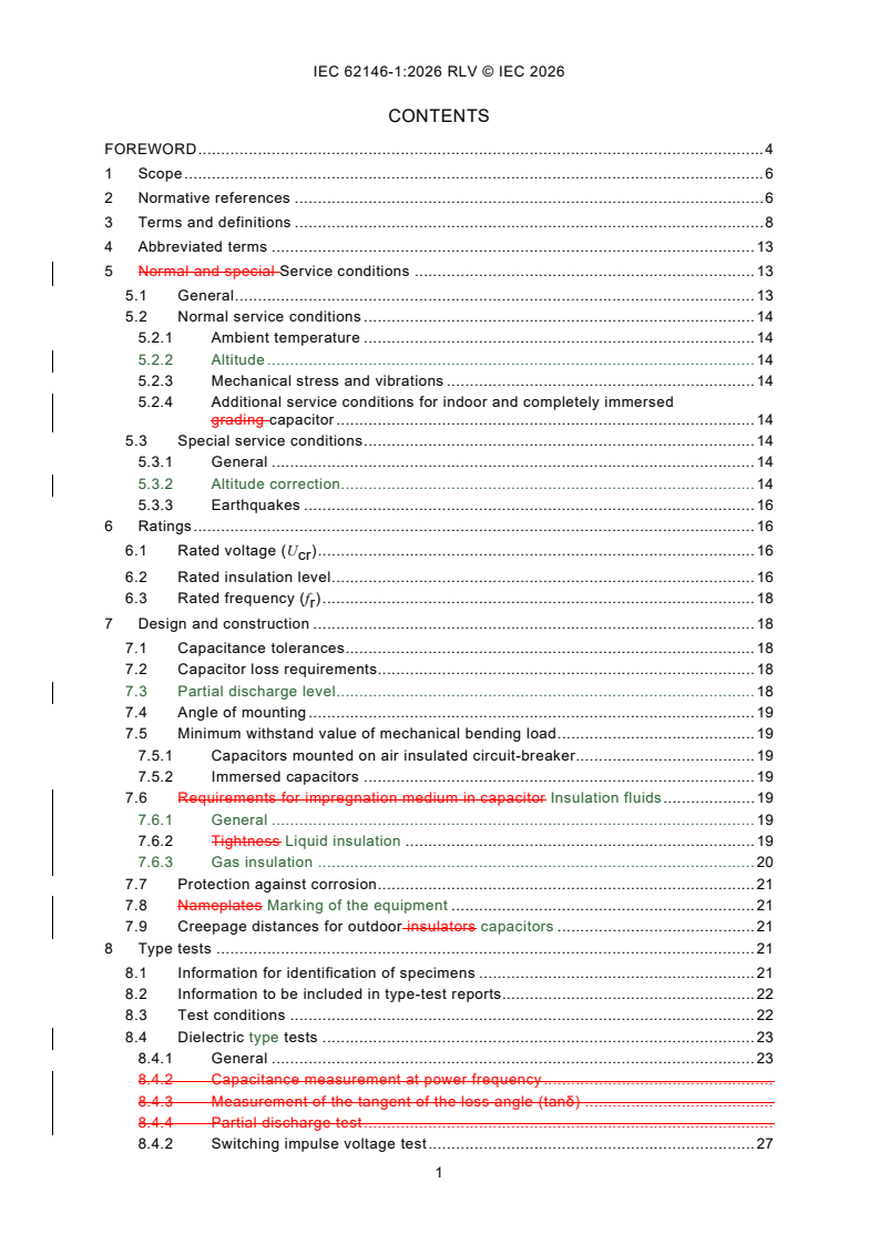
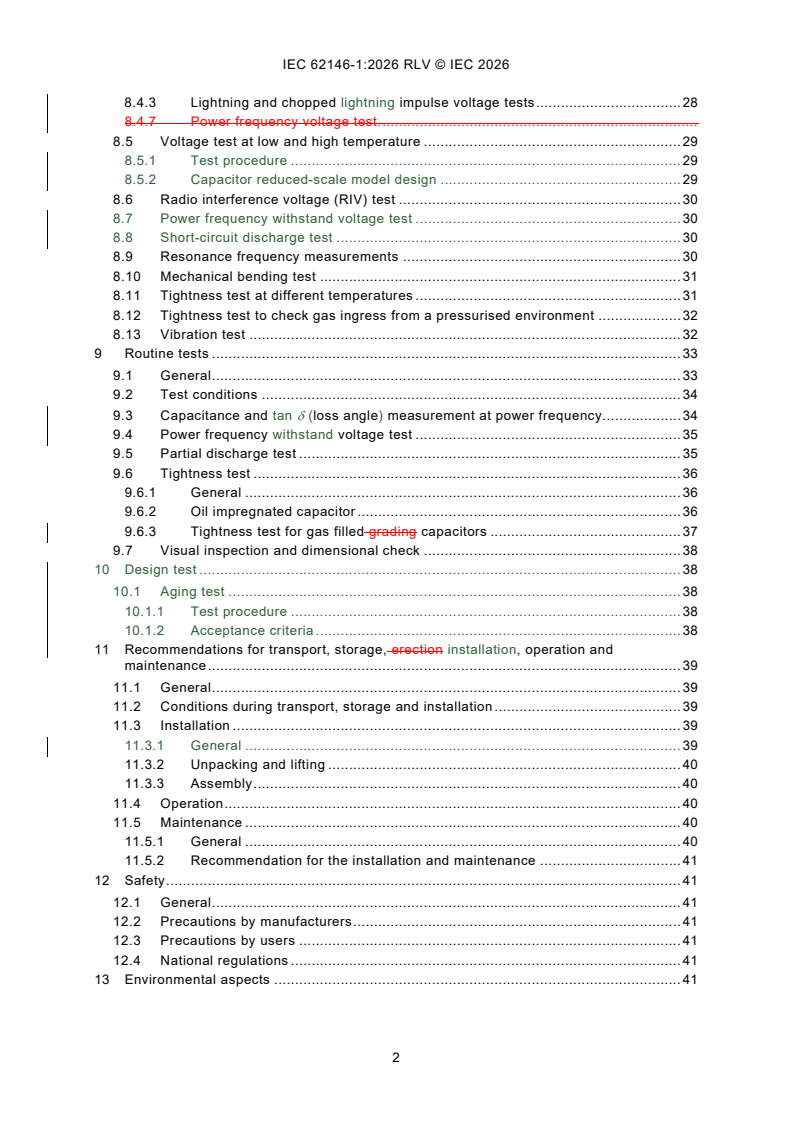
CONTENTS
FOREWORD . 4
1 Scope . 6
2 Normative references . 6
3 Terms and definitions . 8
4 Abbreviated terms . 13
5 Normal and special Service conditions . 13
5.1 General . 13
5.2 Normal service conditions . 14
5.2.1 Ambient temperature . 14
5.2.2 Altitude . 14
5.2.3 Mechanical stress and vibrations . 14
5.2.4 Additional service conditions for indoor and completely immersed
grading capacitor . 14
5.3 Special service conditions . 14
5.3.1 General . 14
5.3.2 Altitude correction. 14
5.3.3 Earthquakes . 16
6 Ratings . 16
6.1 Rated voltage (U ) . 16
cr
6.2 Rated insulation level . 16
6.3 Rated frequency (f ) . 18
r
7 Design and construction . 18
7.1 Capacitance tolerances . 18
7.2 Capacitor loss requirements. 18
7.3 Partial discharge level . 18
7.4 Angle of mounting . 19
7.5 Minimum withstand value of mechanical bending load . 19
7.5.1 Capacitors mounted on air insulated circuit-breaker . 19
7.5.2 Immersed capacitors . 19
7.6 Requirements for impregnation medium in capacitor Insulation fluids . 19
7.6.1 General . 19
7.6.2 Tightness Liquid insulation . 19
7.6.3 Gas insulation . 20
7.7 Protection against corrosion . 21
7.8 Nameplates Marking of the equipment . 21
7.9 Creepage distances for outdoor insulators capacitors . 21
8 Type tests . 21
8.1 Information for identification of specimens . 21
8.2 Information to be included in type-test reports. 22
8.3 Test conditions . 22
8.4 Dielectric type tests . 23
8.4.1 General . 23
8.4.2 Capacitance measurement at power frequency .
8.4.3 Measurement of the tangent of the loss angle (tanδ) .
8.4.4 Partial discharge test .
8.4.2 Switching impulse voltage test . 27
8.4.3 Lightning and chopped lightning impulse voltage tests . 28
8.4.7 Power frequency voltage test. .
8.5 Voltage test at low and high temperature . 29
8.5.1 Test procedure . 29
8.5.2 Capacitor reduced-scale model design . 29
8.6 Radio interference voltage (RIV) test . 30
8.7 Power frequency withstand voltage test . 30
8.8 Short-circuit discharge test . 30
8.9 Resonance frequency measurements . 30
8.10 Mechanical bending test . 31
8.11 Tightness test at different temperatures . 31
8.12 Tightness test to check gas ingress from a pressurised environment . 32
8.13 Vibration test . 32
9 Routine tests . 33
9.1 General . 33
9.2 Test conditions . 34
9.3 Capacitance and tan δ (loss angle) measurement at power frequency . 34
9.4 Power frequency withstand voltage test . 35
9.5 Partial discharge test . 35
9.6 Tightness test . 36
9.6.1 General . 36
9.6.2 Oil impregnated capacitor . 36
9.6.3 Tightness test for gas filled grading capacitors . 37
9.7 Visual inspection and dimensional check . 38
10 Design test . 38
10.1 Aging test . 38
10.1.1 Test procedure . 38
10.1.2 Acceptance criteria . 38
11 Recommendations for transport, storage, erection installation, operation and
maintenance . 39
11.1 General . 39
11.2 Conditions during transport, storage and installation . 39
11.3 Installation . 39
11.3.1 General . 39
11.3.2 Unpacking and lifting . 40
11.3.3 Assembly . 40
11.4 Operation . 40
11.5 Maintenance . 40
11.5.1 General . 40
11.5.2 Recommendation for the installation and maintenance . 41
12 Safety . 41
12.1 General . 41
12.2 Precautions by manufacturers . 41
12.3 Precautions by users . 41
12.4 National regulations . 41
13 Environmental aspects . 41
Annex A (informative) Corrosion: Information regarding service conditions and
recommended test requirements . 43
A.1 General . 43
A.2 Recommended test requirements . 43
Annex B (informative) Resonance frequency measurements . 44
B.1 General . 44
B.2 Time domain method . 45
B.2.1 General . 45
B.2.2 Test procedure . 45
B.2.3 Measurement results . 46
B.3 Frequency domain method . 46
B.3.1 General . 46
B.3.2 Test setup . 46
B.3.3 Measurement results . 47
Bibliography . 49
Figure 1 – Dielectric type tests .
Figure 1 – Factor m for the switching impulse withstand test . 15
Figure 2 – Example of a dielectric type test sequence . 25
Figure 2 – Dielectric routine test .
Figure 3 – Reduced scale model capacitor element geometry . 30
Figure 4 – Example of an electrical routine test sequence . 34
Figure B.1 – Example of resonance frequency measurement recording (see 8.7) .
Figure B.1 – Example of test setup for resonance frequency measurements in time
domain (see 8.9) . 45
Figure B.2 – Example of time domain voltage transient response to calculate
resonance frequency (see 8.9) . 46
Figure B.3 – Wiring diagram of the measuring circuit for the high-frequency response
(adapted from IEC 60358-2, Annex AA) . 47
Figure B.4 – Frequency response of a high voltage capacitor: Impedance magnitude
(blue, solid line) and phase (red, dashed line) . 48
Table 1 – Partial discharge test voltages and permissible levels .
Table 1 – Partial discharge test voltages and permissible levels for grading capacitors . 18
INTERNATIONAL ELECTROTECHNICAL COMMISSION
____________
Grading Capacitors for high-voltage alternating current circuit-breakers -
Part 1: General and grading capacitors
FOREWORD
1) The International Electrotechnical Commission (IEC) is a worldwide organization for standardization comprising
all national electrotechnical committees (IEC National Committees). The object of IEC is to promote international
co-operation on all questions concerning standardization in the electrical and electronic fields. To this end and
in addition to other activities, IEC publishes International Standards, Technical Specifications, Technical Reports,
Publicly Available Specifications (PAS) and Guides (hereafter referred to as "IEC Publication(s)"). Their
preparation is entrusted to technical committees; any IEC National Committee interested in the subject dealt with
may participate in this preparatory work. International, governmental and non-governmental organizations liaising
with the IEC also participate in this preparation. IEC collaborates closely with the International Organization for
Standardization (ISO) in accordance with conditions determined by agreement between the two organizations.
2) The formal decisions or agreements of IEC on technical matters express, as nearly as possible, an international
consensus of opinion on the relevant subjects since each technical committee has representation from all
interested IEC National Committees.
3) IEC Publications have the form of recommendations for international use and are accepted by IEC National
Committees in that sense. While all reasonable efforts are made to ensure that the technical content of IEC
Publications is accurate, IEC cannot be held responsible for the way in which they are used or for any
misinterpretation by any end user.
4) In order to promote international uniformity, IEC National Committees undertake to apply IEC Publications
transparently to the maximum extent possible in their national and regional publications. Any divergence between
any IEC Publication and the corresponding national or regional publication shall be clearly indicated in the latter.
5) IEC itself does not provide any attestation of conformity. Independent certification bodies provide conformity
assessment services and, in some areas, access to IEC marks of conformity. IEC is not responsible for any
services carried out by independent certification bodies.
6) All users should ensure that they have the latest edition of this publication.
7) No liability shall attach to IEC or its directors, employees, servants or agents including individual experts and
members of its technical committees and IEC National Committees for any personal injury, property damage or
other damage of any nature whatsoever, whether direct or indirect, or for costs (including legal fees) and
expenses arising out of the publication, use of, or reliance upon, this IEC Publication or any other IEC
Publications.
8) Attention is drawn to the Normative references cited in this publication. Use of the referenced publications is
indispensable for the correct application of this publication.
9) IEC draws attention to the possibility that the implementation of this document may involve the use of (a)
patent(s). IEC takes no position concerning the evidence, validity or applicability of any claimed patent rights in
respect thereof. As of the date of publication of this document, IEC had not received notice of (a) patent(s), which
may be required to implement this document. However, implementers are cautioned that this may not represent
the latest information, which may be obtained from the patent database available at https://patents.iec.ch. IEC
shall not be held responsible for identifying any or all such patent rights.
This redline version of the official IEC Standard allows the user to identify the changes made
to the previous edition IEC 62146-1:2016. A vertical bar appears in the margin wherever a
change has been made. Additions are in green text, deletions are in strikethrough red text.
IEC 62146-1 has been prepared by IEC technical committee 33: Power capacitors and their
applications. It is an International Standard.
This second edition cancels and replaces the first edition published in 2016. This edition
constitutes a technical revision.
This edition includes the following significant technical changes with respect to the previous
edition:
a) Clause re-ordering and reworked sentences;
b) New type and special tests.
The text of this International Standard is based on the following documents:
Draft Report on voting
33/746/FDIS 33/750/RVD
Full information on the voting for its approval can be found in the report on voting indicated in
the above table.
The language used for the development of this International Standard is English.
This document was drafted in accordance with ISO/IEC Directives, Part 2, and developed in
accordance with ISO/IEC Directives, Part 1 and ISO/IEC Directives, IEC Supplement, available
at www.iec.ch/members_experts/refdocs. The main document types developed by IEC are
described in greater detail at www.iec.ch/publications.
A list of all parts in the IEC 62146 series, published under the general title Capacitors for
high-voltage alternating current circuit-breakers, can be found on the IEC website.
Future documents in this series will carry the new general title as cited above. Titles of existing
documents in this series will be updated at the time of the next edition.
The committee has decided that the contents of this document will remain unchanged until the
stability date indicated on the IEC website under webstore.iec.ch in the data related to the
specific document. At this date, the document will be
– reconfirmed,
– withdrawn, or
– revised.
1 Scope
This part of IEC 62146 is applicable to grading includes generalities of capacitors used on
alternating current circuit-breakers and introduces specifications for grading capacitors.
Regarding grading capacitors, their function is to control the voltage distribution across the
individual interrupter units of a multi-break circuit-breaker.
Grading Capacitors can also be used in parallel to the interrupter unit on single break circuit-
breakers to modify the Transient Recovery Voltage (TRV). This TRV capacitor application is
covered by IEC 62146-2:2023.
The grading capacitor is a sub-component for the circuit-breaker and shall be specified in
accordance with the circuit-breaker specifications.
Capacitors for high-voltage alternating circuit breakers are sub-components for the circuit-
breaker and are specified in accordance with the circuit-breaker specifications according to
IEC 62271-1, IEC 62271-100, and if applicable to IEC 62271-203.
This document applies to grading capacitors falling into one or both of the following categories
for:
− mounting on air-insulated circuit-breakers.
− mounting on enclosed circuit-breakers (for example immersed in SF insulating gas, in oil,
etc.).
The testing for each of the above applications is in some cases different.
The object of this document is:
− to define uniform rules regarding performances, testing and rating;
− to define specific safety rules;
− to provide a guidance for installation and operation.
NOTE CIGRÉ TB-368 presents a study about the operating environment of voltage grading capacitors applied to
high-voltage circuit-breakers (see [2] ).
This document does not apply to phase-to-earth capacitors installed on the circuit-breaker to
modify the Transient Recovery Voltage capacitors not directly associated with high-voltage
alternating current circuit-breakers.
2 Normative references
The following documents are referred to in the text in such a way that some or all of their content
constitutes requirements of this document. For dated references, only the edition cited applies.
For undated references, the latest edition of the referenced document (including any
amendments) applies.
IEC 60050 (all parts), International electrotechnical vocabulary (available at
http://www.electropedia.org)
IEC 60060-1:2010, High-voltage test techniques - Part 1: General terminology and test
requirements
___________
Numbers in square brackets refer to the Bibliography.
IEC 60068-2-17:19942023, Official version in Russian – Basic Environmental testing
procedures - Part 2-17: Tests - Test Q: Sealing
IEC 60071-1:2006, Insulation co-ordination – Part 1: Definitions, principles and rules
IEC 60071-2:2023, Insulation co-ordination - Part 2: Application guidelines
IEC 60270:20002025, High-voltage test techniques - Charge-based measurement of partial
discharges measurements
IEC 60296, Fluids for electrotechnical applications - Mineral insulating oils for electrical
equipment
IEC 60376:2005, Specification of technical grade sulfur hexafluoride (SF ) for use in electrical
equipment
IEC 60507-1:1991, Artificial pollution tests on high-voltage insulators to be used on a.c.
systems
IEC 60567:2011, Oil-filled electrical equipment - Sampling of gases and analysis of free and
dissolved gases in mineral oils and other insulating liquids - Guidance
IEC 60721-1:2002, Classification of environmental conditions – Part 1: Environmental
parameters and their severities
IEC 60815 (all parts), Selection and dimensioning of high-voltage insulators intended for use in
polluted conditions
IEC 60867, Insulating liquids - Specifications for unused liquids based on synthetic aromatic
hydrocarbons
IEC 61099, Insulating liquids - Specifications for unused synthetic organic esters for electrical
purposes
IEC 61462:2007, Composite hollow insulators - Pressurized and unpressurized insulators for
use in electrical equipment with AC rated voltage greater than 1 000 V AC and DC voltage
greater than 1 500 V – Definitions, test methods, acceptance criteria and design
recommendations
IEC 62146-2:2023, Capacitors for high‑voltage alternating current circuit‑breakers - Part 2: TRV
capacitors
IEC 62155:2003, Hollow pressurized and unpressurized ceramic and glass insulators for use in
electrical equipment with rated voltages greater than 1 000 V
IEC 62271-1:2007, High-voltage switchgear and controlgear - Part 1: Common specifications
for alternating current switchgear and controlgear
IEC 62271-100:2008, High-voltage switchgear and controlgear - Part 100: Alternating-current
circuit-breakers
IEC 62271-203:2003, High-voltage switchgear and controlgear - Part 203: AC gas-insulated
metal-enclosed switchgear for rated voltages above 52 kV
IEC 62271-205, High-voltage switchgear and controlgear - Part 205: Compact switchgear
assemblies for rated voltages above 52 kV
IEC 62271-300:2006, High-voltage switchgear and controlgear - Part 300: Seismic qualification
of alternating current circuit-breakers
IEC 62770, Fluids for electrotechnical applications - Unused natural esters for transformers and
similar electrical equipment
IEC 63012, Insulating liquids - Unused modified or blended esters for electrotechnical
applications
IEC Guide 109, Environmental aspects – Inclusion in electrotechnical product standards
CISPR 18-2:1986, Radio interference characteristics of overhead power lines and high-voltage
equipment – Part 2: Methods of measurement and procedure for determining limits
3 Terms and definitions
For the purposes of this document, the following terms and definitions apply.
ISO and IEC maintain terminology databases for use in standardization at the following
addresses:
– IEC Electropedia: available at https://www.electropedia.org/
– ISO Online browsing platform: available at https://www.iso.org/obp
3.1
arcing distance
shortest distance in the air external to the insulator between the metallic parts which normally
have the operating voltage between them
[SOURCE: IEC 60050-471:2007, 471-01-01]
3.2
capacitor element
device consisting essentially of two electrodes separated by a dielectric
[SOURCE: IEC 60050-436:1990, 436-01-03]
3.3
capacitor losses
active power dissipated in the capacitor
[SOURCE: IEC 60050-436:1990, 436-04-10]
3.4
capacitor terminals
terminals intended for electrical and mechanical connection to the terminals of the interrupter
units of circuit-breakers
3.5
capacitance tolerance
permissible difference between the actual capacitance and the rated capacitance under
specified conditions
Note 1 to entry: The actual capacitance should be measured at, or referred to, the temperature at which the rated
capacitance is defined.
[SOURCE: IEC 60050-436:1990, 436-04-01, modified by addition of Note to entry.]
3.6
capacitor unit
assembly of one or more capacitor elements connected together and in the same container with
terminals brought out
Note 1 to entry: A common type of unit for grading capacitors has a cylindrical housing of insulating material and
metal end flanges which serve as terminals.
[SOURCE: IEC 60050-436:1990, 436-01-04, modified by addition of Note to entry]
3.7
completely immersed capacitor
capacitor, both ends of which are intended to be immersed in insulating media other than
ambient air (e.g. oil or gas)
[SOURCE: IEC 60050-471:2007, 471-02-04, modified - definition originally referred to "bushing"
instead of "capacitor".]
3.8
creepage distance
shortest distance along the surface of a solid insulating material between two conductive parts
Note 1 to entry: The surface of cement or any other non-insulating jointing material is not considered as forming
part of the creepage distance.
Note 2 to entry: If high-resistance coating is applied to parts of the insulating part of an insulator, such parts are
considered to be effective insulating surface and the distance over them is included in the creepage distance.
[SOURCE: IEC 60050-604:1987, 604-03-61, modified by addition of Notes to entry.]
3.9
dielectric (of a capacitor)
insulating material between the electrodes of the capacitor element
Note 1 to entry: The major insulation generally consists of paper, plastic film, or a mixed of paper and plastic film
subsequently treated and impregnated with oil or gas at atmospheric pressure or higher.
3.10
external insulation
distance in through the air and the surfaces in contact with open the air of insulation of the
grading capacitor that are subjected to dielectric stresses
Note 1 to entry: They are also subject to the effects of the atmospheric and other external conditions such as
pollution, humidity, ice, vermin, etc.
3.11
failure
termination of the ability of an item to perform a required function
Note 1 to entry: After failure the item has a fault.
Note 2 to entry: "Failure" is an event, as distinguished from "fault", which is a state.
Note 3 to entry: This concept as defined does not apply to items consisting of software only.
[SOURCE: IEC 60050-191:1990, 191-04-01]
3.12
flashover
electric breakdown between conductors in a gas or in a liquid or in a vacuum, at least partly
along the surface of solid insulation
[SOURCE: IEC 60050-212:2012, 212-11-47]
3.13
grading capacitor
capacitor for installation on high-voltage circuit-breakers to control the voltage distribution
across the individual interrupter unit
Note 1 to entry: The grading capacitors alone are accessories of the circuit-breaker.
3.14
indoor capacitor
capacitor, both ends of which are intended to be in ambient air at atmospheric pressure but not
exposed to outdoor atmospheric conditions
[SOURCE: IEC 60050-471:2007, 471-02-05, modified - definition originally referred to "bushing"
instead of "capacitor".]
3.15
insulating envelope
insulator which is open from end to end, with or without sheds, including end fittings
Note 1 to entry: An insulating envelope can be made from one or more permanently assembled insulating elements.
Note 2 to entry: The insulating envelope may be in ceramic, glass or analogous inorganic material, cast or moulded
resin, composite insulating material, in one piece or more pieces permanently assembled.
[SOURCE: IEC 60050-471:2007, 471-01-08, modified - definition originally referred to a hollow
insulator and Note 2 to entry has been added.]
3.16
outdoor capacitor
capacitor, both ends of which are intended to be in ambient air at atmospheric pressure, and
exposed to outdoor atmospheric conditions
[SOURCE: IEC 60050-471:2007, 471-02-07, modified - definition originally referred to "bushing"
instead of "capacitor".]
3.17
internal insulation
internal solid, liquid or gaseous parts of the insulation of the grading capacitor which are
protected from the effects of atmospheric conditions
Note 1 to entry: The parts are also protected from other external conditions such as pollution, humidity, ice, vermin,
etc.
3.18
major failure (of a grading capacitor)
failure of a grading capacitor which causes the cessation of its fundamental function.
Note 1 to entry: A major failure will result in a mandatory removal from service within 30 min for unscheduled
maintenance.
3.18
mechanical stress
any mechanical stress applied to the insulating envelope and to the terminals of the grading
capacitor
Note 1 to entry: It is a function of the following main forces:
− forces on the terminals due to the circuit-breaker connection;
− forces due to the wind and ice;
− seismic forces;
− forces due to the operating conditions, opening and closing, of the circuit- breaker;
− thermal forces due to the ambient medium conditions;
− forces due to the transportation of the circuit-breaker or grading capacitors.
3.20
minor failure (of a grading capacitor)
any failure of a grading capacitor which does not cause a major failure of the grading capacitor
3.19
puncture
disruptive discharge occurring through a solid insulation material, producing a path of
permanent damage
Note 1 to entry: The term puncture is also used as a synonym for electrical breakdown in solids.
[SOURCE: IEC 60050-212:2010, 212-11-49]
3.20
rated capacitance of a capacitor
C
r
capacitance value for which the capacitor has been designed
3.21
rated chopped lightning impulse withstand voltage
required peak value of the chopped lightning impulse withstand voltage which characterises the
insulation of a grading capacitor as regards the withstand tests
Note 1 to entry: The definitions and the standard parameters applicable to chopped impulses are specified in
IEC 60060-1.
3.22
rated frequency of a capacitor
f
r
frequency for which the capacitor has been designed
[SOURCE: IEC 60050-436:1990, 436-01-14, modified by addition of symbol.]
3.23
rated insulation level
test voltages, under specified conditions, that the insulation is designed to withstand
Note 1 to entry: These test voltages can be for instance:
a) rated chopped and lightning impulse and short duration power frequency withstand voltages for capacitors
installed on circuit-breaker with rated voltage lower than 300 kV.
b) rated switching, lightning, chopped impulse and short duration power frequency withstand voltages for capacitors
installed on circuit-breaker with rated voltage equal to or greater than 300 kV.
Note 2 to entry: The rated insulation levels of the grading capacitor should be equal to or higher than the relevant
requirements for the circuit-breaker interrupting unit.
[SOURCE: IEC 60050-421:1990, 421-09-02, modified Note to entry]
3.24
rated lightning impulse withstand voltage
U
C LI
required peak value of the lightning impulse withstand voltage which characterises the
insulation of an equipment as regards the withstand tests
Note 1 to entry: The standard lightning impulse has a front time of 1,2 µs and a time-to-half-value of 50 µs as
specified in IEC 60060-1.
3.25
rated short duration power frequency withstand voltage
U
C PF
required RMS value of sinusoidal power frequency voltage that the equipment withstands during
tests made under specified conditions and for a duration of 1 min unless otherwise specified
3.26
rated switching impulse withstand voltage
U
C SI
required peak value of the switching impulse withstand voltage which characterises the
insulation of an equipment as regards the withstand tests
Note 1 to entry: The standard switching impulse has a time-to-crest of 250 µs and a time-to-half-value of 2 500 µs
as specified in IEC 60060-1.
3.27
rated temperature category (of a capacitor)
range of temperature of the ambient air or other medium in which the capacitor is immersed
during the service life and for which it has been designed
3.28
rated voltage of a capacitor
U
cr
RMS value of the alternating voltage assigned to the capacitor for identification and at which
the capacitor is designed to operate continuously
3.29
rated voltage of circuit-breaker
U
r
indicates the upper limit of the highest voltage of systems for which the circuit-breaker is
intended
Note 1 to entry: See IEC 62271-1.
Note 2 to entry: U used in IEC 62271-1 series corresponds to Um presented in IEC 60071.
r
3.30
resonance frequency
frequency for which the reactance of the intrinsic capacitance of the capacitor is equal to the
reactance of the self-inductance of the capacitor
3.31
sample
device for testing
Note 1 to entry: Examples of such devices are a complete small capacitor, or the housing of a grading capacitor
with metal end flanges filled with impregnating fluid.
3.32
tangent of the loss angle of a capacitor
tan δ
ratio between the equivalent series resistance and the capacitive reactance of a capacitor at
specified sinusoidal alternating voltage and frequency
[SOURCE: IEC 60050-436:1990, 436-04-11]
3.33
voltage grading factor of a circuit-breaker
F
VG
value that defines the standard values of rated voltages for the grading capacitor
Note 1 to entry: This factor is the ratio between the actual maximum power frequency voltage fraction across one
interrupter unit of a multi-break circuit-breaker and the calculated linear power frequency voltage distribution per
interrupting unit.
Note 2 to entry: It is dependent on the circuit-breaker design, of the capacitance value of the grading capacitor and
its tolerance and of the safety margin.
4 Abbreviated terms
TRV Transient Recovery Voltage
Rated capacitance of a capacitor
C
r
f Rated frequency of a capacitor
r
U Rated voltage of a capacitor
cr
U Rated voltage of circuit-breaker
r
tan δ Tangent of the loss angle of a capacitor
F Voltage grading factor of a circuit-breaker
VG
U Rated short-duration power frequency withstand voltage for the grading
C PF
capacitor
U Rated short-duration power frequency withstand voltage across the open
PF
circuit-breaker
U U Rated lightning impulse withstand voltage for the grading capacitor
CLIWL C LI
U Combined lightning and power frequency withstand voltage for the circuit-
(LIWL LI + PF)
breaker
U U Rated switching impulse withstand voltage for the grading capacitor
CSIWL C SI
U Combined switching and power frequency withstand voltage for the circuit-
(SIWL SI + PF)
breaker
U U Chopped lightning impulse voltage for the grading capacitor
CCHOPPED C LIC
BIL Bushings insulated level
SIL Standard insulation level
RIV Radio interference voltage
ESR Equivalent series resistance
5 Normal and special Service conditions
5.1 General
The grading capacitors mentioned in this document are intended to be installed on circuit-
breakers, for which the normal and special service conditions are described in IEC 62271-1.
Additional service conditions specific to the capacitors are given in 5.2.3.
5.2 Normal service conditions
5.2.1 Ambient temperature
For outdoor application the normal service conditions of the grading capacitor are given in
IEC 62271-1.
For an immersed capacitor, the temperature around the capacitor can be higher than the
ambient air around the breaker. The preferred values of maximum surrounding temperature to
be specified should be: 60 °C, 70 °C, 80 °C.
The internal operating temperature of the capacitor is higher than the maximum temperature
around the capacitor and should be considered by the capacitor manufacturer.
5.2.2 Altitude
The altitude does not exceed 1 000 m.
5.2.3 Mechanical stress and vibrations
Mechanical stress and vibrations can be due to:
– forces due to wind and ice according to IEC 62271-1;
– forces on the terminals due to the circuit-breaker connection which value shall be defined
by agreement between purchaser and capacitor manufacturer;
– forces due to the operations consequent to vibrations, such as opening and closing, of the
circuit-breaker.
Vibrations due to earthquakes are not considered for normal service conditions.
5.2.4 Additional service conditions for indoor and completely immersed grading
capacitor
The completely immersed grading capacitors are subjected to the following other conditions:
– the influence of SF the insulating gas pressure;
– the resistance of the capacitor materials against the decomposition products of SF the
insulating gas.
5.3 Special service conditions
5.3.1 General
The special service conditions are given in IEC 62271-1; if they are required, the purchaser will
specify it to the capacitor manufacturer.
5.3.2 Altitude correction
The coordination withstand voltages are considered valid up to an altitude of 1 000 m. To
consider the reduced withstand capability of the air at an installation site with an altitude above
1 000 m, the required type test insulation withstand level of external insulation at standard
reference atmospheric conditions shall be determined by multiplying the withstand voltage
required on site by an altitude correction factor K . The correction factor shall not be applied
a
for routine tests, because a routine test validates the quality of the internal insulation only.
For AC applications, the altitude correction factor shall be determined in accordance with
IEC 60071-2:2023, 7.2.2, using Formula H.13 from IEC 60071-2:2023 as follows:
H −1 000
( )
m
8 150
K = e
a
where
H
...
IEC 62146-1 ®
Edition 2.0 2026-07
NORME
INTERNATIONALE
Condensateurs pour disjoncteurs à courant alternatif haute tension -
Partie 1: Généralités et condensateurs de répartition
ICS 31.060.01; 31.060.70 ISBN 978-2-8327-1381-5
Droits de reproduction réservés. Sauf indication contraire, aucune partie de cette publication ne peut être reproduite ni
utilisée sous quelque forme que ce soit et par aucun procédé, électronique ou mécanique, y compris la photocopie et
les microfilms, sans l'accord écrit de l'IEC ou du Comité national de l'IEC du pays du demandeur. Si vous avez des
questions sur le copyright de l'IEC ou si vous désirez obtenir des droits supplémentaires sur cette publication, utilisez
les coordonnées ci-après ou contactez le Comité national de l'IEC de votre pays de résidence.
IEC Secretariat Tel.: +41 22 919 02 11
3, rue de Varembé info@iec.ch
CH-1211 Geneva 20 www.iec.ch
Switzerland
A propos de l'IEC
La Commission Electrotechnique Internationale (IEC) est la première organisation mondiale qui élabore et publie des
Normes internationales pour tout ce qui a trait à l'électricité, à l'électronique et aux technologies apparentées.
A propos des publications IEC
Le contenu technique des publications IEC est constamment revu. Veuillez vous assurer que vous possédez l’édition la
plus récente, un corrigendum ou amendement peut avoir été publié.
Recherche de publications IEC - IEC Products & Services Portal - products.iec.ch
webstore.iec.ch/advsearchform Découvrez notre puissant moteur de recherche et consultez
La recherche avancée permet de trouver des publications gratuitement tous les aperçus des publications, symboles
IEC en utilisant différents critères (numéro de référence, graphiques et le glossaire. Avec un abonnement, vous aurez
texte, comité d’études, …). Elle donne aussi des toujours accès à un contenu à jour adapté à vos besoins.
informations sur les projets et les publications remplacées
ou retirées. Electropedia - www.electropedia.org
Le premier dictionnaire d'électrotechnologie en ligne au
IEC Just Published - webstore.iec.ch/justpublished monde, avec plus de 22 500 articles terminologiques en
Restez informé sur les nouvelles publications IEC. Just anglais et en français, ainsi que les termes équivalents
dans 25 langues additionnelles. Egalement appelé
Published détaille les nouvelles publications parues.
Disponible en ligne et une fois par mois par email. Vocabulaire Electrotechnique International (IEV) en ligne.
Service Clients - webstore.iec.ch/csc
Si vous désirez nous donner des commentaires sur cette
publication ou si vous avez des questions contactez-
nous: sales@iec.ch.
SOMMAIRE
AVANT-PROPOS . 4
1 Domaine d’application . 6
2 Références normatives . 6
3 Termes et définitions . 8
4 Abréviations . 13
5 Conditions de service . 13
5.1 Généralités . 13
5.2 Conditions normales de service . 14
5.2.1 Température ambiante . 14
5.2.2 Altitude . 14
5.2.3 Contraintes et vibrations mécaniques . 14
5.2.4 Conditions de service supplémentaires pour un condensateur utilisé en
intérieur et immergé totalement . 14
5.3 Conditions spéciales de service . 14
5.3.1 Généralités . 14
5.3.2 Correction d’altitude . 14
5.3.3 Séismes . 16
6 Caractéristiques assignées . 16
6.1 Tension assignée (U ) . 16
cr
6.2 Niveau d’isolement assigné. 16
6.3 Fréquence assignée (f ) . 17
r
7 Conception et construction . 17
7.1 Tolérances de capacité . 17
7.2 Exigences concernant les pertes d’un condensateur . 17
7.3 Niveau de décharges partielles . 18
7.4 Angle d’installation . 18
7.5 Valeur de tenue minimale de la charge de flexion mécanique . 18
7.5.1 Condensateurs montés sur un disjoncteur isolé dans l’air . 18
7.5.2 Condensateurs immergés . 19
7.6 Fluides isolants . 19
7.6.1 Généralités . 19
7.6.2 Isolation liquide . 19
7.6.3 Isolation du gaz . 20
7.7 Protection contre la corrosion . 20
7.8 Marquage du matériel . 21
7.9 Lignes de fuite pour les condensateurs d’extérieur . 21
8 Essais de type . 21
8.1 Informations pour l’identification des éprouvettes . 21
8.2 Informations à inclure dans les rapports d’essai de type . 22
8.3 Conditions d’essai . 22
8.4 Essais de type diélectriques . 23
8.4.1 Généralités . 23
8.4.2 Essai de tenue à la tension de choc de manœuvre . 24
8.4.3 Essai de tension de chocs de foudre et de chocs coupés . 24
8.5 Essai de tension à basse et haute températures . 25
8.5.1 Mode opératoire d’essai . 25
8.5.2 Conception du modèle de condensateur à échelle réduite . 25
8.6 Essais de tension de perturbation radioélectrique (RIV) . 26
8.7 Essai de tension de tenue à fréquence industrielle. 26
8.8 Essai de décharge en court-circuit . 26
8.9 Mesurages de la fréquence de résonance . 27
8.10 Essai de flexion mécanique. 27
8.11 Essai d’étanchéité à des températures différentes . 27
8.12 Essai d'étanchéité permettant de vérifier la pénétration de gaz
d'un environnement sous pression . 28
8.13 Essai de vibrations. 28
9 Essais individuels de série . 29
9.1 Généralités . 29
9.2 Conditions d’essai . 29
9.3 Mesurage de la capacité et de tan δ (angle de perte) à fréquence industrielle . 29
9.4 Essai de tension de tenue à fréquence industrielle. 30
9.5 Essai de décharges partielles . 31
9.6 Essai d’étanchéité . 31
9.6.1 Généralités . 31
9.6.2 Condensateurs imprégnés d’huile . 31
9.6.3 Essai d’étanchéité pour des condensateurs remplis de gaz . 32
9.7 Inspection visuelle et vérification dimensionnelle . 33
10 Essai de conception . 33
10.1 Essai de vieillissement . 33
10.1.1 Mode opératoire d’essai . 33
10.1.2 Critères d’acceptation . 34
11 Recommandations pour le transport, le stockage, l’installation, le fonctionnement
et la maintenance . 34
11.1 Généralités . 34
11.2 Conditions applicables au transport, au stockage et à l’installation . 34
11.3 Installation . 35
11.3.1 Généralités . 35
11.3.2 Déballage et levage . 35
11.3.3 Assemblage . 35
11.4 Fonctionnement . 35
11.5 Maintenance . 36
11.5.1 Généralités . 36
11.5.2 Recommandations pour l'installation et la maintenance . 36
12 Sécurité . 36
12.1 Généralités . 36
12.2 Mesures de précaution à prendre par les constructeurs . 36
12.3 Mesures de précaution à prendre par les utilisateurs . 36
12.4 Réglementations nationales . 37
13 Aspects liés à l’environnement . 37
Annexe A (informative) Corrosion: informations concernant les conditions de service
et exigences d’essai recommandées . 38
A.1 Généralités . 38
A.2 Exigences d'essai recommandées . 38
Annexe B (informative) Mesurages de la fréquence de résonance . 39
B.1 Généralités . 39
B.2 Méthode de mesure dans le domaine temporel . 39
B.2.1 Généralités . 39
B.2.2 Mode opératoire d’essai . 40
B.2.3 Résultats de mesure . 41
B.3 Méthode de mesure dans le domaine fréquentiel . 41
B.3.1 Généralités . 41
B.3.2 Montage d’essai . 41
B.3.3 Résultats de mesure . 42
Bibliographie . 44
Figure 1 – Facteur m pour l’essai de tenue aux chocs de manœuvre . 15
Figure 2 – Exemple de séquence d’essais de type diélectriques . 23
Figure 3 – Géométrie d’un modèle d’élément de condensateur à échelle réduite . 26
Figure 4 – Exemple de séquence d’essais électriques individuels de série. 29
Figure B.1 – Exemple de montage d'essai pour les mesurages de fréquence
de résonance dans le domaine temporel (voir 8.9) . 40
Figure B.2 – Exemple de réponse transitoire de tension dans le domaine temporel
pour calculer la fréquence de résonance (voir 8.9) . 41
Figure B.3 – Schéma de câblage du circuit de mesure pour la réponse à haute
fréquence (adapté de l'IEC 60358-2, Annexe AA) . 42
Figure B.4 – Réponse en fréquence d'un condensateur à haute tension : amplitude
(ligne bleue) et phase (ligne de pointillés rouge) de l'impédance . 43
Tableau 1 – Tensions d’essai de décharges partielles et niveaux admissibles
pour les condensateurs de répartition . 18
COMMISSION ÉLECTROTECHNIQUE INTERNATIONALE
____________
Condensateurs pour disjoncteurs à courant alternatif haute tension -
Partie 1: Généralités et condensateurs de répartition
AVANT-PROPOS
1) La Commission Électrotechnique Internationale (IEC) est une organisation mondiale de normalisation composée
de l’ensemble des comités électrotechniques nationaux (Comités nationaux de l’IEC). L’IEC a pour objet
de favoriser la coopération internationale pour toutes les questions de normalisation dans les domaines
de l’électricité et de l’électronique. À cet effet, l’IEC – entre autres activités – publie des Normes internationales,
des Spécifications techniques, des Rapports techniques, des Spécifications accessibles au public (PAS) et
des Guides (ci-après dénommés "Publication(s) de l’IEC"). Leur élaboration est confiée à des comités d’études,
aux travaux desquels tout Comité national intéressé par le sujet traité peut participer. Les organisations
internationales, gouvernementales et non gouvernementales, en liaison avec l’IEC, participent également
aux travaux. L’IEC collabore étroitement avec l’Organisation Internationale de Normalisation (ISO), selon
des conditions fixées par accord entre les deux organisations.
2) Les décisions ou accords officiels de l’IEC concernant les questions techniques représentent, dans la mesure
du possible, un accord international sur les sujets étudiés, étant donné que les Comités nationaux de l’IEC
intéressés sont représentés dans chaque comité d’études.
3) Les Publications de l’IEC se présentent sous la forme de recommandations internationales et sont agréées
comme telles par les Comités nationaux de l’IEC. Tous les efforts raisonnables sont entrepris afin que l’IEC
s’assure de l’exactitude du contenu technique de ses publications; l’IEC ne peut pas être tenue responsable
de l’éventuelle mauvaise utilisation ou interprétation qui en est faite par un quelconque utilisateur final.
4) Dans le but d’encourager l’uniformité internationale, les Comités nationaux de l’IEC s’engagent, dans toute
la mesure possible, à appliquer de façon transparente les Publications de l’IEC dans leurs publications nationales
et régionales. Toutes divergences entre toutes Publications de l’IEC et toutes publications nationales ou
régionales correspondantes doivent être indiquées en termes clairs dans ces dernières.
5) L’IEC elle-même ne fournit aucune attestation de conformité. Des organismes de certification indépendants
fournissent des services d’évaluation de conformité et, dans certains secteurs, accèdent aux marques
de conformité de l’IEC. L’IEC n’est responsable d’aucun des services effectués par les organismes de certification
indépendants.
6) Tous les utilisateurs doivent s’assurer qu’ils sont en possession de la dernière édition de cette publication.
7) Aucune responsabilité ne doit être imputée à l’IEC, à ses administrateurs, employés, auxiliaires ou mandataires,
y compris ses experts particuliers et les membres de ses comités d’études et des Comités nationaux de l’IEC,
pour tout préjudice causé en cas de dommages corporels et matériels, ou de tout autre dommage de quelque
nature que ce soit, directe ou indirecte, ou pour supporter les coûts (y compris les frais de justice) et les dépenses
découlant de la publication ou de l’utilisation de cette Publication de l’IEC ou de toute autre Publication de l’IEC,
ou au crédit qui lui est accordé.
8) L’attention est attirée sur les références normatives citées dans cette publication. L’utilisation de publications
référencées est obligatoire pour une application correcte de la présente publication.
9) L’IEC attire l’attention sur le fait que la mise en application du présent document peut entraîner l’utilisation
d’un ou de plusieurs brevets. L’IEC ne prend pas position quant à la preuve, à la validité et à l’applicabilité de tout
droit de brevet revendiqué à cet égard. À la date de publication du présent document, l’IEC n’avait pas reçu
notification qu’un ou plusieurs brevets pouvaient être nécessaires à sa mise en application. Toutefois, il y a lieu
d’avertir les responsables de la mise en application du présent document que des informations plus récentes
sont susceptibles de figurer dans la base de données de brevets, disponible à l’adresse https://patents.iec.ch.
L’IEC ne saurait être tenue pour responsable de ne pas avoir identifié tout ou partie de tels droits de brevet.
L’IEC 62146-1 a été établie par le comité d’études 33 de l’IEC: Condensateurs de puissance et
leurs applications. Il s’agit d’une Norme internationale.
Cette deuxième édition annule et remplace la première édition parue en 2016. Cette édition
constitue une révision technique.
Cette édition inclut les modifications techniques majeures suivantes par rapport à l’édition
précédente:
a) réorganisation des articles et reformulation des phrases;
b) nouveaux essais de type et essais spéciaux.
Le texte de cette Norme internationale est issu des documents suivants:
Projet Rapport de vote
33/746/FDIS 33/750/RVD
Le rapport de vote indiqué dans le tableau ci-dessus donne toute information sur le vote ayant
abouti à son approbation.
La langue employée pour l’élaboration de cette Norme internationale est l’anglais.
Ce document a été rédigé selon les Directives ISO/IEC, Partie 2, il a été développé
selon les Directives ISO/IEC, Partie 1 et les Directives ISO/IEC, Supplément IEC, disponibles
sous www.iec.ch/members_experts/refdocs. Les principaux types de documents développés
par l’IEC sont décrits plus en détail sous www.iec.ch/publications.
Une liste de toutes les parties de la série IEC 62146, publiées sous le titre général
Condensateurs pour disjoncteurs à courant alternatif haute tension, peut être consultée
sur le site web de l’IEC.
Les futurs documents de cette série porteront le nouveau titre général cité ci-dessus.
Le titre des documents qui existent déjà dans cette série sera mis à jour lors de leur prochaine
édition.
Le comité a décidé que le contenu de ce document ne sera pas modifié avant la date de stabilité
indiquée sur le site web de l’IEC sous webstore.iec.ch dans les données relatives au document
recherché. À cette date, le document sera
– reconduit,
– supprimé, ou
– révisé.
1 Domaine d’application
La présente partie de l’IEC 62146 expose des généralités concernant les condensateurs utilisés
sur les disjoncteurs à courant alternatif et présente des spécifications relatives
aux condensateurs de répartition. Les condensateurs de répartition ont pour fonction
de contrôler la répartition de la tension entre chaque interrupteur d'un disjoncteur à coupure
multiple.
Les condensateurs peuvent également être utilisés parallèlement à l'interrupteur
de disjoncteurs à coupure unique afin de modifier la tension transitoire de rétablissement (TTR).
Cette application des condensateurs TTR est couverte par l’IEC 62146-2:2023.
Les condensateurs pour disjoncteurs à courant alternatif haute tension
sont des sous-composants du disjoncteur et sont spécifiés conformément aux spécifications
des disjoncteurs de l’IEC 62271-1, l’IEC 62271-100 et, le cas échéant, l’IEC 62271-203.
Le présent document s'applique aux condensateurs de répartition relevant de l'une
des catégories suivantes, ou des deux:
− condensateurs montés sur des disjoncteurs isolés dans l’air;
− condensateurs montés sur des disjoncteurs protégés (par exemple, immergés dans du gaz
isolant, dans l'huile, etc.).
L'essai applicable à chacune des applications susmentionnées est différent dans certains cas.
Le présent document a pour objet:
− de définir des règles uniformes concernant les performances, les essais et
les caractéristiques assignées;
− de définir des règles de sécurité spécifiques;
− de fournir des recommandations pour l’installation et le fonctionnement.
NOTE Le document CIGRÉ TB-368 présente une étude sur l'environnement de fonctionnement des condensateurs
de répartition de la tension dans les applications de disjoncteurs à haute tension (voir [2] ).
Le présent document ne s’applique pas aux condensateurs qui ne sont pas directement
associés aux disjoncteurs à courant alternatif haute tension.
2 Références normatives
Les documents suivants sont cités dans le texte de sorte qu’ils constituent, pour tout ou partie
de leur contenu, des exigences du présent document. Pour les références datées,
seule l’édition citée s’applique. Pour les références non datées, la dernière édition du document
de référence s’applique (y compris les éventuels amendements).
IEC 60060-1, Technique des essais à haute tension - Partie 1: Terminologie générale et
exigences d’essai
IEC 60068-2-17:2023, Essais d’environnement - Partie 2-17: Essais - Essai Q: Étanchéité
IEC 60071-2:2023, Coordination de l’isolement - Partie 2: Lignes directrices en matière
d'application
___________
Les chiffres entre crochets renvoient à la Bibliographie.
IEC 60270:2025, Techniques des essais à haute tension - Mesurages des décharges partielles
fondés sur les charges
IEC 60296, Fluides pour applications électrotechniques - Huiles minérales isolantes pour
matériel électrique
IEC 60567,Matériels électriques immergés - Échantillonnage de gaz libres et analyse des gaz
libres et dissous dans les huiles minérales et d’autres liquides isolants - Recommandations
IEC 60815 (toutes les parties), Selection and dimensioning of high-voltage insulators intended
for use in polluted conditions (disponible en anglais seulement)
IEC 60867, Isolants liquides - Spécifications pour les liquides neufs à base d'hydrocarbures
aromatiques de synthèse
IEC 61099, Liquides isolants - Spécifications relatives aux esters organiques de synthèse neufs
destinés aux matériels électriques
IEC 61462, Isolateurs composites creux - Isolateurs avec ou sans pression interne pour
utilisation dans des appareillages électriques de tensions alternatives assignées supérieures à
1 000 V et de tensions continues supérieures à 1 500 V - Définitions, méthodes d’essai, critères
d’acceptation et recommandations de conception
IEC 62146-2:2023, Condensateurs pour disjoncteurs à courant alternatif haute tension -
Partie 2: Condensateurs TTR
IEC 62155:2003, Isolateurs creux avec ou sans pression interne, en matière céramique ou en
verre, pour utilisation dans des appareillages électriques prévus pour des tensions nominales
supérieures à 1 000 V
IEC 62271-1, Appareillage à haute tension - Partie 1: Spécifications communes pour
appareillage à courant alternatif
IEC 62271-100, Appareillage à haute tension - Partie 100: Disjoncteurs à courant alternatif
IEC 62271-203, Appareillage à haute tension - Partie 203: Appareillage sous enveloppe
métallique à isolation gazeuse et à courant alternatif de tensions assignées supérieures à 52 kV
IEC 62271-205, Appareillage à haute tension - Partie 205: Ensembles d’appareillages
compacts de tensions assignées supérieures à 52 kV
IEC 62271-300, Appareillage à haute tension - Partie 300: Qualification sismique des
disjoncteurs à courant alternatif
IEC 62770, Fluides pour applications électrotechniques - Esters naturels neufs pour
transformateurs et matériels électriques analogues
IEC 63012, Isolants liquides - Esters neufs modifiés ou mélangés pour applications
électrotechniques
3 Termes et définitions
Pour les besoins du présent document, les termes et définitions suivants s’appliquent.
L’ISO et l’IEC tiennent à jour des bases de données terminologiques destinées à être utilisées
en normalisation, consultables aux adresses suivantes:
– IEC Electropedia: disponible à l’adresse https://www.electropedia.org/
– ISO Online browsing platform: disponible à l’adresse https://www.iso.org/obp
3.1
distance d’arc
plus courte distance dans l’air à l’extérieur de l’isolateur entre les parties métalliques
sur lesquelles on applique normalement la tension de service
[SOURCE: IEC 60050-471:2007, 471-01-01]
3.2
élément de condensateur
dispositif constitué essentiellement par deux électrodes séparées par un diélectrique
[SOURCE: IEC 60050-436:1990, 436-01-03]
3.3
pertes d’un condensateur
puissance active dissipée dans le condensateur
[SOURCE: IEC 60050-436:1990, 436-04-10]
3.4
bornes de condensateur
bornes destinées à être connectées électriquement et mécaniquement aux bornes
des interrupteurs des disjoncteurs
3.5
tolérance de capacité
différence admise entre la valeur réelle de la capacité et la valeur assignée dans des conditions
spécifiées
Note 1 à l’article: Il convient de mesurer la capacité réelle à, ou en référence à, la température à laquelle la capacité
assignée est définie.
[SOURCE: IEC 60050-436:1990, 436-04-01, modifié par l'ajout de la Note 1 à l'article]
3.6
unité de condensateur
ensemble d’un ou plusieurs éléments de condensateurs placés dans une même enveloppe et
reliés à des bornes de sortie
Note 1 à l’article: Un type courant d'unité de condensateurs de répartition comprend un boîtier cylindrique
en matériau isolant et des talons d'extrémité métalliques servant de bornes.
[SOURCE: IEC 60050-436:1990, 436-01-04, modifié par l'ajout de la Note 1 à l'article]
3.7
condensateur immergé totalement
condensateur dont les deux extrémités sont destinées à l’immersion dans des milieux isolants
autres que l'air (par exemple huile ou gaz)
[SOURCE: IEC 60050-471:2007, 471-02-04, modifié - La définition faisait initialement référence
à des "traversées" en lieu et place des "condensateurs"]
3.8
ligne de fuite
distance la plus courte, le long de la surface d’un isolant solide, entre deux parties conductrices
Note 1 à l’article: La surface du ciment ou de toute autre matière de scellement non isolante n’est pas considérée
comme faisant partie de la ligne de fuite.
Note 2 à l’article: Si un revêtement à haute résistance est appliqué sur certaines parties isolantes d’un isolateur,
ces parties sont considérées comme surfaces isolantes effectives et la distance mesurée à la surface de ces parties
est incluse dans la ligne de fuite.
[SOURCE: IEC 60050-604:1987, 604-03-61, modifié par l'ajout des Notes 1 et 2 à l'article]
3.9
diélectrique (d’un condensateur)
matériau isolant entre les électrodes de l'élément de condensateur
Note 1 à l’article: La principale isolation est généralement constituée de papier, d’un film en matière plastique ou
d’un mélange de papier et de film en matière plastique qui est ensuite traité et imprégné d’huile ou de gaz à pression
atmosphérique ou supérieure.
3.10
isolation externe
distance dans l'air et sur les surfaces du condensateur de répartition en contact avec l'air,
qui sont soumises aux contraintes diélectriques
Note 1 à l’article: Elles sont également soumises à l'influence des conditions atmosphériques ou d'autres conditions
externes telles que la pollution, l'humidité, la glace, les animaux, etc.
3.11
défaillance
cessation de l’aptitude d’une entité à accomplir une fonction exigée
Note 1 à l’article: Après une défaillance, l’appareil présente une panne.
Note 2 à l’article: Une défaillance est un passage d’un état à un autre, par opposition à une panne, qui est un état.
Note 3 à l’article: La notion de défaillance, telle qu’elle est définie, ne s’applique pas à une entité constituée
seulement de logiciel.
[SOURCE: IEC 60050-191:1990, 191-04-01]
3.12
contournement
claquage électrique entre des conducteurs dans un gaz, un liquide ou le vide, au moins
en partie le long de la surface d'une isolation solide
[SOURCE: IEC 60050-212:2012, 212-11-47]
3.13
condensateur de répartition
condensateur destiné à être installé sur des disjoncteurs haute tension afin de contrôler
la répartition de la tension sur chaque interrupteur
Note 1 à l’article: Les condensateurs de répartition seuls constituent des accessoires du disjoncteur.
3.14
condensateur d'intérieur
condensateur dont les deux extrémités sont destinées à être dans l'air ambiant à la pression
atmosphérique mais non soumises aux conditions atmosphériques extérieures
[SOURCE: IEC 60050-471:2007, 471-02-05, modifié - La définition faisait initialement référence
à des "traversées" en lieu et place des "condensateurs"]
3.15
enveloppe isolante
isolateur creux, ouvert de part en part, équipé ou non d’ailettes, incluant les armatures
d’extrémité
Note 1 à l’article: Une enveloppe isolante peut être constituée d’un ou plusieurs éléments d’isolateurs assemblés
d’une façon permanente.
Note 2 à l’article: L'enveloppe isolante peut être constituée d'un matériau céramique, de verre ou d'un matériau
inorganique analogue, de résine coulée ou moulée, d'un matériau isolant composite, en une ou plusieurs pièces
assemblées d'une façon permanente.
[SOURCE: IEC 60050-471:2007, 471-01-08, modifié - La définition faisait initialement référence
à un "isolateur creux" et une Note 2 à l’article a été ajoutée]
3.16
condensateur d'extérieur
condensateur dont les deux extrémités sont destinées à être dans l'air ambiant à la pression
atmosphérique et soumises aux conditions atmosphériques extérieures
[SOURCE: IEC 60050-471:2007, 471-02-07, modifié - La définition faisait initialement référence
à des "traversées" en lieu et place des "condensateurs"]
3.17
isolation interne
éléments internes solides, liquides ou gazeux de l'isolation du condensateur de répartition
qui sont à l'abri de l'influence des conditions atmosphériques
Note 1 à l’article: Ces éléments sont également à l’abri de l’influence d’autres conditions externes
telles que la pollution, l’humidité, la glace, les animaux, etc.
3.18
contrainte mécanique
toute contrainte mécanique appliquée à l'enveloppe isolante et aux bornes du condensateur
Note 1 à l’article: La contrainte mécanique est fonction des principales forces suivantes:
− les forces exercées sur les bornes produites par la connexion du disjoncteur;
− les forces produites par le vent et la glace;
− les forces sismiques;
− les forces produites par les conditions de fonctionnement, à savoir ouverture et fermeture, du disjoncteur;
− les forces thermiques produites par les conditions ambiantes;
− les forces produites par le transport du disjoncteur ou des condensateurs.
3.19
perforation
décharge disruptive se produisant à travers un matériau d’isolation solide, créant un chemin
de destruction permanente
Note 1 à l’article: Ce terme est aussi utilisé comme synonyme de claquage électrique dans les solides.
[SOURCE: IEC 60050-212:2010, 212-11-49]
3.20
capacité assignée d'un condensateur
C
r
valeur de la capacité pour laquelle le condensateur a été conçu
3.21
tension de tenue coupée assignée aux chocs de foudre
valeur de crête exigée de la tension de tenue coupée aux chocs de foudre qui caractérise
l'isolation d'un condensateur eu égard aux essais de tenue
Note 1 à l’article: Les définitions et les paramètres normalisés applicables aux chocs coupés sont spécifiés
dans l’IEC 60060-1.
3.22
fréquence assignée d'un condensateur
f
r
fréquence pour laquelle le condensateur a été conçu
[SOURCE: IEC 60050-436:1990, 436-01-14, modifié par l'ajout du symbole]
3.23
niveau d’isolement assigné
tensions d'essai que l'isolation doit pouvoir supporter dans des conditions spécifiées
Note 1 à l’article: Ces tensions d'essai peuvent être par exemple:
a) des tensions de tenue coupées assignées aux chocs de foudre et des tensions de tenue de courte durée
à fréquence industrielle pour les condensateurs installés sur un disjoncteur de tension assignée inférieure
à 300 kV;
b) des tensions de tenue assignées aux chocs de manœuvre et aux chocs de foudre, des tensions de tenue
aux chocs coupés et des tensions de tenue de courte durée à fréquence industrielle pour les condensateurs
installés sur un disjoncteur de tension assignée supérieure ou égale à 300 kV.
Note 2 à l’article: Il convient que les niveaux d'isolement assignés du condensateur soient supérieurs ou égaux
aux exigences pertinentes concernant l'interrupteur du disjoncteur.
[SOURCE: IEC 60050-421:1990, 421-09-02 - Les notes à l’article ont été modifiées]
3.24
tension de tenue assignée aux chocs de foudre
U
C LI
valeur de crête exigée de la tension de tenue aux chocs de foudre qui caractérise l'isolation
d'un matériel eu égard aux essais de tenue
Note 1 à l’article: La tension de choc de foudre normalisée a un temps de montée de 1,2 µs et une durée jusqu’à
la mi-valeur de 50 µs comme spécifié dans l’IEC 60060-1.
3.25
tension de tenue assignée de courte durée à fréquence industrielle
U
C PF
valeur efficace exigée de la tension sinusoïdale à fréquence industrielle à laquelle le matériel
peut résister au cours des essais réalisés dans des conditions spécifiées et pendant une durée
de 1 min sauf spécification contraire
3.26
tension de tenue assignée aux chocs de manœuvre
U
C SI
valeur de crête exigée de la tension de tenue aux chocs de manœuvre qui caractérise l'isolation
d'un matériel eu égard aux essais de tenue
Note 1 à l’article: La tension de choc de manœuvre normalisée a une durée jusqu’à la crête de 250 µs et une durée
jusqu’à la mi-valeur 2 500 µs comme spécifié dans l’IEC 60060-1.
3.27
catégorie de température assignée (d'un condensateur)
plage de température de l'air ambiant ou d'un autre milieu dans lequel le condensateur
est immergé pendant la durée de vie en service et pour laquelle il a été conçu
3.28
tension assignée d'un condensateur
U
cr
valeur efficace de la tension alternative attribuée au condensateur pour identification et
à laquelle ce dernier est conçu pour fonctionner de manière continue
3.29
tension assignée d'un disjoncteur
U
r
indique la limite supérieure de la tension maximale des systèmes pour lesquels le disjoncteur
est destiné
Note 1 à l’article: Voir l’IEC 62271-1.
Note 2 à l’article: U utilisée dans la série IEC 62271-1 correspond à la valeur Um présentée dans l’IEC 60071.
r
3.30
fréquence de résonance
fréquence pour laquelle la réactance de la capacité intrinsèque du condensateur est égale
à la réactance de l'inductance propre du condensateur
3.31
échantillon
dispositif pour essai
Note 1 à l’article: Un condensateur complet de petite dimension ou le boîtier d'un condensateur de répartition
avec des talons d'extrémité métalliques remplis de fluide d'imprégnation constituent des exemples de ce type
de dispositifs.
3.32
tangente de l'angle de perte d'un condensateur
tan δ
rapport entre la résistance-série équivalente et la réactance capacitive du condensateur
dans des conditions spécifiées de fréquence et de tension alternative sinusoïdale
[SOURCE: IEC 60050-436:1990, 436-04-11]
3.33
facteur de répartition de la tension d'un disjoncteur
F
VG
valeur qui définit les valeurs normalisées des tensions assignées du condensateur
de répartition
Note 1 à l’article: Ce facteur est le rapport entre la fraction réelle de tension maximale à fréquence industrielle
aux bornes d’un interrupteur d'un disjoncteur à coupure multiple et la répartition calculée linéairement de la tension
à fréquence industrielle par interrupteur.
Note 2 à l’article: Ce facteur dépend de la conception du disjoncteur, de la valeur de capacité du condensateur
de répartition et sa tolérance, ainsi que de la marge de sécurité.
4 Abréviations
TTR Tension Transitoire de Rétablissement
C Capacité assignée d'un condensateur
r
f Fréquence assignée d'un condensateur
r
U Tension assignée d'un condensateur
cr
U Tension assignée d’un disjoncteur
r
tan δ Tangente de l'angle de perte d'un condensateur
F Facteur de répartition de la tension d'un disjoncteur
VG
U Tension assignée de tenue de courte durée à fréquence industrielle pour
C PF
le condensateur de répartition
U Tension assignée de tenue de courte durée à fréquence industrielle aux bornes
PF
du disjoncteur ouvert
U Tension de tenue assignée aux chocs de foudre pour le condensateur de répartition
C LI
U Tension combinée de tenue aux chocs de foudre et à fréquence industrielle
(LI + PF)
pour le disjoncteur
U Tension de tenue assignée aux chocs de manœuvre pour le condensateur
C SI
de répartition
U Tension combinée de tenue aux chocs de manœuvre et à fréquence industrielle
(SI + PF)
pour le disjoncteur
U Tension de tenue aux chocs de foudre coupés pour le condensateur de répartition
C LIC
RIV Tension de perturbation radioélectrique
RSE Résistance-Série Équivalente
5 Conditions de service
5.1 Généralités
Les condensateurs mentionnés dans le présent document sont destinés à être installés
sur des disjoncteurs, pour lesquels les conditions normales et spéciales de service
sont décrites dans l’IEC 62271-1.
Les conditions de service supplémentaires spécifiques aux condensateurs sont définies
en 5.2.3.
5.2 Conditions normales de service
5.2.1 Température ambiante
Pour une application en extérieur, les conditions normales de service du condensateur
de répartition sont données dans l’IEC 62271-1.
Pour un condensateur immergé, la température environnante du condensateur peut être
supérieure à l'air ambiant autour du disjoncteur. Il convient que les valeurs préférentielles de la
température environnante maximale à spécifier soient les suivantes: 60 °C, 70 °C, 80 °C.
La température de fonctionnement interne du condensateur est supérieure à la température
maximale environnante du condensateur et il convient qu’elle soit prise en compte
par le constructeur du condensateur.
5.2.2 Altitude
L’altitude ne dépasse pas 1 000 m.
5.2.3 Contraintes et vibrations mécaniques
Les contraintes et vibrations mécaniques peuvent être engendrées par:
– les forces produites par l'action du vent et de la glace selon l’IEC 62271-1;
– les forces exercées sur les bornes produites par la connexion des disjoncteurs dont la valeur
doit être définie par accord entre l'acheteur et le constructeur du condensateur;
– les forces produites par les opérations conséquentes aux vibrations, à savoir ouverture et
fermeture, du disjoncteur.
5.2.4 Conditions de service supplémentaires pour un condensateur utilisé en
intérieur et immergé totalement
Les condensateurs immergés totalement sont soumis aux autres conditions suivantes:
– l'influence de la pression du gaz isolant;
– la résistance des matériaux constitutifs du condensateur aux produits de décomposition
du gaz isolant.
5.3 Conditions spéciales de service
5.3.1 Généralités
Les conditions spéciales de service sont décrites dans l’IEC 62271-1; lorsqu'elles sont exigées,
l'acheteur les spécifiera au constructeur du condensateur.
5.3.2 Correction d’altitude
Les tensions de tenue de coordination sont considérées comme valides jusqu’à une altitude
de 1 000 m. Pour tenir compte de la tenue réduite de l’air sur un site d’installation à une altitude
supérieure à 1 000 m, le niveau de tenue de l’isolation externe exigé pour l’essai de type,
dans les conditions atmosphériques de référence normales, doit être déterminé en multipliant
la tension de tenue exigée sur site par un facteur de correction d’altitude K . Le facteur
a
de correction ne doit pas être appliqué pour les essais individuels de série car un essai
individuel valide uniquement la
...