

SIST EN 14587-3:2026
(Main)Railway applications - Infrastructure - Flash butt welding of rails - Part 3: Welding in association with crossing construction
- Abstract
This document specifies requirements for the approval of a welding process in a fixed plant, together with the requirements for subsequent welding production.
This document applies to new Vignole rails manufactured in accordance to EN 13674 1 and welded by flash butt welding to crossing components in a fixed plant, and intended for use on railway infrastructures.
This document applies to cast Manganese crossings manufactured to EN 15689, fabricated crossings manufactured from rail and crossings manufactured from forged/rolled premium steels.
NOTE EN 14587-1 is also used for the flash butt welding of switches.
Sometimes special profiles exist in crossing construction, which are not rail profiles as defined in EN 13674 series (example: profile with machined off rail foot). In these cases, tests are defined by the railway authority in participation with the manufacturer.
- Status
- Published
- Public Enquiry End Date
- 31-Mar-2025
- Publication Date
- 20-Oct-2026
- Technical Committee
- IŽNP - Reilway applications
- Current Stage
- 6060 - National Implementation/Publication (Adopted Project)
- Start Date
- 21-Oct-2026
- Due Date
- 26-Dec-2026
- Completion Date
- 21-Oct-2026

EN 14587-3 is a CEN standard for railway applications - infrastructure - flash butt welding of rails in association with crossing construction. It specifies how a welding process is approved in a fixed plant, and how the resulting welds are produced, inspected and tested for railway infrastructure use.
The standard is aimed at manufacturers, purchasers and railway authorities that need a controlled welding process for rails joined to crossing components, including cast Manganese crossings, fabricated crossings made from rail, and crossings made from forged or rolled premium steels.
What does EN 14587-3 specify?
EN 14587-3 specifies requirements for approving a flash butt welding process in a fixed plant, and for the production of those welds after approval. It covers new Vignole rails, crossing components and rail leg-end extensions used in railway infrastructure.
The document is organized from general information and definitions through manufacturer approval, welding controls, geometry, procedure approval, optional approval of other rail profiles or grades, track trials, and production requirements.
A few important scope points matter in practice:
- The welding is for fixed plant use, not mobile site welding.
- The scope includes cast Manganese crossings, fabricated crossings and crossings from forged or rolled premium steels.
- Special crossing profiles that are not rail profiles are handled by tests agreed by the railway authority (RA) with the manufacturer.
- EN 14587-1 is noted for flashed butt welding of switches.
| Annex | What it covers |
|---|---|
| Annex A | Examples of flat spots and die burn |
| Annex B | Bend test requirements |
| Annex C | Recording defects on weld fracture faces |
| Annex D | Fatigue test method for flash butt welds |
| Annex E | Macro-examination and micro-examination |
| Annex F | Hardness testing |
| Annex G | Ultrasonic testing for non-austenitic materials |
| Annex H | Measurement of alignment and flatness |
What are the key requirements of EN 14587-3?
EN 14587-3 requires a controlled, recorded welding process, with procedure approval before production and ongoing checks during production. In practice, the document is mainly about controlling preparation, welding parameters, weld geometry, and destructive and non-destructive testing.
Process approval and manufacturer control
Clause 5 requires the manufacturer to use RA-approved welding procedures and machines, competent operators, supervision, inspection and a quality management system accepted by the purchaser. Clause 4 also requires both purchaser and manufacturer to supply documented information such as rail profile, materials, tolerance needs, traceability and machine identification.
This matters because the standard is built around traceable, repeatable production. The purchaser and manufacturer must agree the exact profile, material, fatigue-test needs and other project details before approval starts.
Welding preparation and execution
Clause 6 requires automatic programmed flash butt welding in a fixed plant. The workpieces must be sawn, disc cut or machined first, kept clean at electrical contact areas, and corrected if mismatch exceeds 2 mm.
The clause also controls burn-off, preheating, final flashing, upsetting and post-weld treatment. In practice, this means the plant must run a defined weld cycle and keep records of current, force, displacement, time, programme identification, weld identification and any post-weld heat treatment.
Finishing and geometry
Clause 7 requires longitudinal profile finishing by machining or grinding, with limits on surface roughness in the welded zone and a maximum rail-head finishing length of 900 mm. Clause 8 then sets alignment, flatness and foot-dimension requirements, including class-based tolerances for horizontal and vertical alignment.
This matters because the weld must not only be strong, but also fit the rail profile and running surface. The document uses a 1 m straightedge for alignment and a 200 mm straightedge for flatness, while foot thickness is checked with a NO GO Gauge.
Procedure approval testing
Clause 10 is the core approval clause. It calls for visual and geometry checks, surface finish checks, non-destructive testing, bend testing, macro-examination, hardness testing, and either micro-examination or fatigue testing, depending on what the RA requires.
The test program is designed to prove the process before production starts. Annex B through Annex G give the test methods, and Clause 10 also defines how failures, fracture faces and retesting are handled.
Production testing and retention of records
Clause 13 applies after approval. Weld parameters must be monitored and recorded for all welds, visual and geometry checks continue in production, and bend testing is required at least weekly and after events such as a machine malfunction, overhaul or a long idle period.
This matters for day-to-day quality control. The records must be kept for not less than five years, so the plant can show that routine production stayed within the approved process.
Approval of other profiles, grades and track trials
Clauses 11 and 12 let an approved process be extended to other rail profiles or grades under defined conditions, and they allow track trials if the RA requires field verification. That means laboratory approval may not be the end of the approval path when a project uses a different profile, grade or track situation.
What terms does EN 14587-3 define?
- austenitic component - A part made from high manganese steel with an austenitic microstructure.
- insert - An intermediate part between the rail and the crossing, used when the crossing is made from austenitic manganese steel.
- manufacturer - The company that flash butt welds rails to rails, rails to crossings, or rails to crossing components in a fixed plant.
- purchaser - The buyer of the flash butt welded crossings, working under railway authority requirements.
- fixed plant - A stationary machine for flash butt welding rails to rails, rails to crossings or rails to crossing components.
- flat spot - A local smooth-textured feature seen in section, often lens-shaped in macro view.
- lack of bond - An area in the weld where there is no metal-to-metal contact.
- railway authority (RA) - The regulator, infrastructure owner or custodian with delegated railway responsibility.
Who uses EN 14587-3?
EN 14587-3 is used by crossing manufacturers, rail welders, fixed-plant operators, purchasers and railway authorities. It is also used by NDT personnel, quality managers and test laboratories that support weld approval and production control.
In practice, these users apply it to:
- approve a welding procedure before production
- qualify operators and welding equipment
- check weld geometry, surface condition and internal soundness
- run bend, fatigue, macro, micro and hardness testing
- manage traceability, records and retesting
- define project-specific requirements for special crossing profiles
What changed in EN 14587-3 from the previous edition?
EN 14587-3 supersedes EN 14587-3:2012. The foreword states these main technical changes:
- clarified how foot dimensions are measured, with a gauge and reference table
- clearer instruction for the testing sequence and more detail for visual inspection
- better description of flat spots and clearer criteria for microstructure examination
- criteria for cross acceptance of materials
- added bend test requirements for high strength steels
- a new annex for geometrical inspection guidance
Which standards are used with EN 14587-3?
EN 14587-3 refers to these standards for specific supporting requirements:
- EN 13018 - gives general principles for visual testing.
- EN ISO 3452-1 - gives penetrant testing principles used for liquid penetrant testing.
- EN ISO 9712 - sets qualification and certification requirements for NDT personnel.
- EN 13674-1, EN 13674-2 and EN 13674-4 - define the rail profiles and rail types used with this standard.
- EN 14587-1:2018 - is the related fixed-plant flash butt welding part for rail grades used with switches.
- EN 17343 - supplies general terms and definitions.
- EN ISO 6507-1 - gives the Vickers hardness test method.
- EN ISO 7500-1:2018 - gives calibration and verification rules for testing machines.
- EN ISO 11666, EN ISO 17638, EN ISO 17640, EN ISO 23278:2015 and EN ISO 23279 - support ultrasonic, magnetic particle and acceptance-level checking.
What does the EN 14587-3 document contain?
EN 14587-3 contains the full approval and production framework for flash butt welding rails to crossing components in a fixed plant. It includes test matrices, acceptance classes, weld geometry tolerances, bend-test arrangements, fatigue-test procedures, macro and micro sectioning methods, hardness traverse rules and ultrasonic reference blocks.
It also includes figures and tables for:
- rail end squareness and weld alignment
- foot-thickness gauging
- bend-test arrangements and minimum loads
- fracture-face defect recording
- fatigue-test calibration and test rigs
- macro- and micro-examination sampling
- hardness measurement locations
- ultrasonic DAC reference lines and acceptance criteria
For a user, the practical value is that the standard tells the plant what to agree up front, what to record during welding, what to test during approval, and what to keep under routine production control.
Relations
- Effective Date
- 01-Dec-2026
- Referred By
SIST EN 16432-3:2022 - Railway applications - Ballastless track systems - Part 3: Acceptance - Effective Date
- 21-Oct-2026
- Effective Date
- 21-Oct-2026
Get Certified
Connect with accredited certification bodies for this standard

DVS-ZERT GmbH
German welding certification society.
CARES (UK Certification Authority for Reinforcing Steels)
UK certification for reinforcing steels and construction.
EWF/IIW (European/International Welding Federation)
International welding personnel certification.
Sponsored listings
Frequently Asked Questions
SIST EN 14587-3:2026 is a standard published by the Slovenian Institute for Standardization (SIST). Its full title is "Railway applications - Infrastructure - Flash butt welding of rails - Part 3: Welding in association with crossing construction". This standard covers: This document specifies requirements for the approval of a welding process in a fixed plant, together with the requirements for subsequent welding production. This document applies to new Vignole rails manufactured in accordance to EN 13674 1 and welded by flash butt welding to crossing components in a fixed plant, and intended for use on railway infrastructures. This document applies to cast Manganese crossings manufactured to EN 15689, fabricated crossings manufactured from rail and crossings manufactured from forged/rolled premium steels. NOTE EN 14587-1 is also used for the flash butt welding of switches. Sometimes special profiles exist in crossing construction, which are not rail profiles as defined in EN 13674 series (example: profile with machined off rail foot). In these cases, tests are defined by the railway authority in participation with the manufacturer.
This document specifies requirements for the approval of a welding process in a fixed plant, together with the requirements for subsequent welding production. This document applies to new Vignole rails manufactured in accordance to EN 13674 1 and welded by flash butt welding to crossing components in a fixed plant, and intended for use on railway infrastructures. This document applies to cast Manganese crossings manufactured to EN 15689, fabricated crossings manufactured from rail and crossings manufactured from forged/rolled premium steels. NOTE EN 14587-1 is also used for the flash butt welding of switches. Sometimes special profiles exist in crossing construction, which are not rail profiles as defined in EN 13674 series (example: profile with machined off rail foot). In these cases, tests are defined by the railway authority in participation with the manufacturer.
SIST EN 14587-3:2026 is classified under the following ICS (International Classification for Standards) categories: 25.160.10 - Welding processes; 93.100 - Construction of railways. The ICS classification helps identify the subject area and facilitates finding related standards.
SIST EN 14587-3:2026 has the following relationships with other standards: It is inter standard links to SIST EN 14587-3:2012, SIST EN 16432-3:2022, SIST EN 13231-1:2013. Understanding these relationships helps ensure you are using the most current and applicable version of the standard.
SIST EN 14587-3:2026 is associated with the following European legislation: EU Directives/Regulations: 2016/797/EU, 2016/797/EU, 2016/797/EU, 2016/797/EU, 2016/797/EU, 2016/797/EU, 2016/797/EU, 2016/797/EU, 2016/797/EU, 2016/797/EU, 2016/797/EU, 2016/797/EU, 2016/797/EU; Standardization Mandates: M/024, M/483. When a standard is cited in the Official Journal of the European Union, products manufactured in conformity with it benefit from a presumption of conformity with the essential requirements of the corresponding EU directive or regulation.
SIST EN 14587-3:2026 is available in PDF format for immediate download after purchase. The document can be added to your cart and obtained through the secure checkout process. Digital delivery ensures instant access to the complete standard document.
Standards Content (Sample)
SLOVENSKI STANDARD
01-december-2026
Nadomešča:
SIST EN 14587-3:2012
Železniške naprave - Infrastruktura - Elektrouporovno varjenje tirnic - 3. del:
Varjenje pri izdelavi kretnic
Railway applications - Infrastructure - Flash butt welding of rails - Part 3: Welding in
association with crossing construction
Bahnanwendungen - Infrastruktur - Abbrennstumpfschweißen von Schienen – Teil 3:
Schweißen im Zusammenhang mit Herzstückkonstruktionen
Applications ferroviaires - Voie - Soudage des rails par étincelage - Partie 3 : Soudure en
association avec la construction des appareils de voie
Ta slovenski standard je istoveten z: EN 14587-3:2026
ICS:
25.160.10 Varilni postopki in varjenje Welding processes
93.100 Gradnja železnic Construction of railways
2003-01.Slovenski inštitut za standardizacijo. Razmnoževanje celote ali delov tega standarda ni dovoljeno.
EN 14587-3
EUROPEAN STANDARD
NORME EUROPÉENNE
October 2026
EUROPÄISCHE NORM
ICS 25.160.10; 93.100 Supersedes EN 14587-3:2012
English Version
Railway applications - Infrastructure - Flash butt welding
of rails - Part 3: Welding in association with crossing
construction
Applications ferroviaires - Voie - Soudage des rails par Bahnanwendungen - Infrastruktur -
étincelage - Partie 3 : Soudure en association avec la Abbrennstumpfschweißen von Schienen - Teil 3:
construction des appareils de voie Schweißen im Zusammenhang mit
Herzstückkonstruktionen
This European Standard was approved by CEN on 17 August 2026.
CEN members are bound to comply with the CEN/CENELEC Internal Regulations which stipulate the conditions for giving this
European Standard the status of a national standard without any alteration. Up-to-date lists and bibliographical references
concerning such national standards may be obtained on application to the CEN-CENELEC Management Centre or to any CEN
member.
This European Standard exists in three official versions (English, French, German). A version in any other language made by
translation under the responsibility of a CEN member into its own language and notified to the CEN-CENELEC Management
Centre has the same status as the official versions.
CEN members are the national standards bodies of Austria, Belgium, Bulgaria, Croatia, Cyprus, Czech Republic, Denmark, Estonia,
Finland, France, Germany, Greece, Hungary, Iceland, Ireland, Italy, Latvia, Lithuania, Luxembourg, Malta, Netherlands, Norway,
Poland, Portugal, Republic of North Macedonia, Romania, Serbia, Slovakia, Slovenia, Spain, Sweden, Switzerland, Türkiye and
United Kingdom.
EUROPEAN COMMITTEE FOR STANDARDIZATION
COMITÉ EUROPÉEN DE NORMALISATION
EUROPÄISCHES KOMITEE FÜR NORMUNG
CEN-CENELEC Management Centre: Rue de la Science 23, B-1040 Brussels
© 2026 CEN All rights of exploitation in any form and by any means reserved Ref. No. EN 14587-3:2026 E
worldwide for CEN national Members.
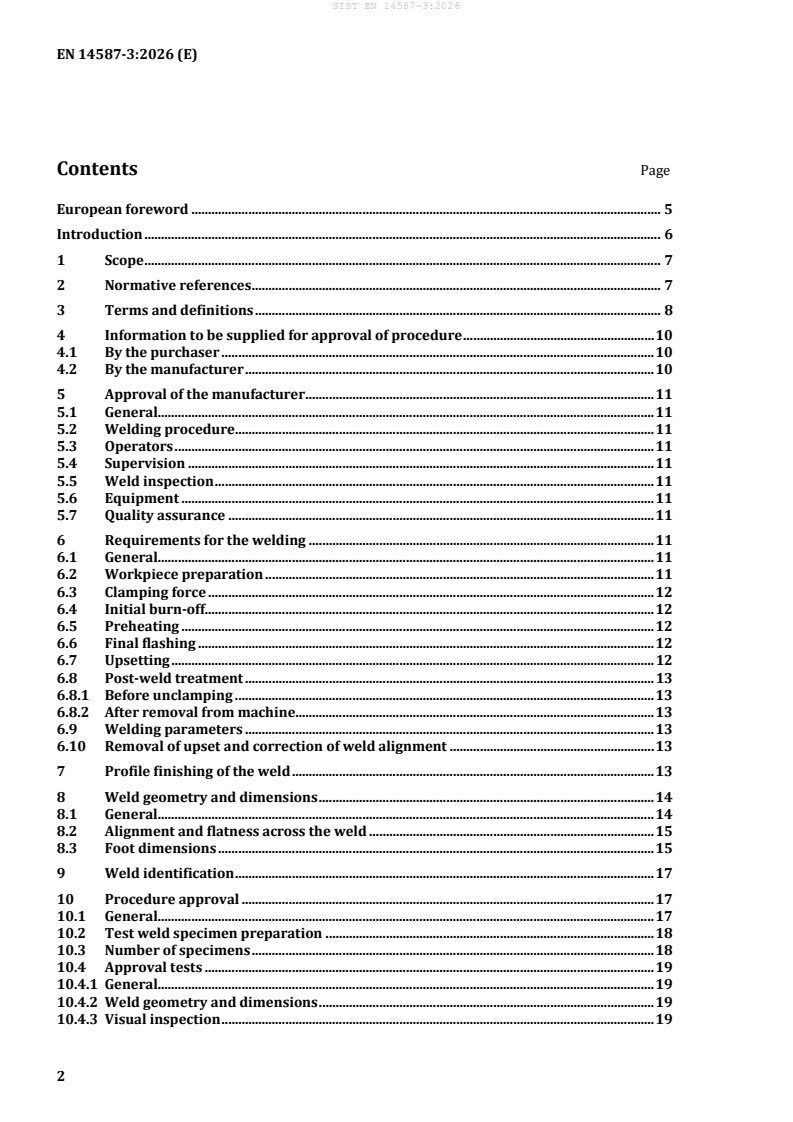
Contents Page
European foreword . 5
Introduction . 6
1 Scope . 7
2 Normative references . 7
3 Terms and definitions . 8
4 Information to be supplied for approval of procedure . 10
4.1 By the purchaser . 10
4.2 By the manufacturer . 10
5 Approval of the manufacturer . 11
5.1 General. 11
5.2 Welding procedure . 11
5.3 Operators . 11
5.4 Supervision . 11
5.5 Weld inspection . 11
5.6 Equipment . 11
5.7 Quality assurance . 11
6 Requirements for the welding . 11
6.1 General. 11
6.2 Workpiece preparation . 11
6.3 Clamping force . 12
6.4 Initial burn-off . 12
6.5 Preheating . 12
6.6 Final flashing . 12
6.7 Upsetting . 12
6.8 Post-weld treatment . 13
6.8.1 Before unclamping . 13
6.8.2 After removal from machine. 13
6.9 Welding parameters . 13
6.10 Removal of upset and correction of weld alignment . 13
7 Profile finishing of the weld . 13
8 Weld geometry and dimensions . 14
8.1 General. 14
8.2 Alignment and flatness across the weld . 15
8.3 Foot dimensions . 15
9 Weld identification . 17
10 Procedure approval . 17
10.1 General. 17
10.2 Test weld specimen preparation . 18
10.3 Number of specimens . 18
10.4 Approval tests . 19
10.4.1 General. 19
10.4.2 Weld geometry and dimensions . 19
10.4.3 Visual inspection . 19
10.4.4 Surface finish . 20
10.4.5 Liquid penetrant testing and magnetic particle testing . 20
10.4.6 Internal soundness . 20
10.4.7 Bend test . 21
10.4.8 Fatigue testing . 21
10.4.9 Macro-examination . 21
10.4.10 Micro-examination . 22
10.4.11 Hardness testing . 23
10.5 Test result report . 23
10.6 Validity of approval. 24
11 Approval of other rail profiles or grades . 24
11.1 General . 24
11.2 Sample preparation . 25
11.3 Test result report . 25
12 Track trials . 25
12.1 General . 25
12.2 Track trial test result report . 25
13 Weld production following procedure approval . 26
13.1 Weld production . 26
13.2 Weld parameter monitoring. 26
13.3 Visual inspections . 26
13.4 Weld geometry and dimensions . 26
13.5 Liquid penetrant testing and magnetic particle testing . 26
13.6 Internal soundness . 26
13.7 Bend testing . 26
13.7.1 General . 26
13.7.2 Additional test requirements . 26
13.7.3 Bend test procedure . 27
13.7.4 Interpretation of results . 27
13.7.5 Retesting . 27
13.7.6 Documentation . 28
Annex A (informative) Example of flat spots: lenticular-type and grey spot . 29
Annex B (normative) Bend test requirements . 31
Annex C (normative) Test weld fracture faces – Recording of defects . 34
Annex D (normative) Fatigue test method for flash butt welds . 36
D.1 Scope . 36
D.2 Test equipment. 36
D.3 Calibration procedure. 38
D.3.1 General . 38
D.3.2 Test piece . 38
D.3.3 Test piece preparation . 38
D.3.4 Instrumentation . 38
D.3.5 Procedure . 38
D.4 Fatigue test method . 43
D.4.1 General . 43
D.4.2 Staircase testing method . 43
D.4.3 Example of the data analysis of a fatigue strength determination by the staircase
method . 45
D.4.4 Past-the-post testing method . 46
Annex E (normative) Macro-examination and micro-examination . 48
E.1 Macro-examination . 48
E.2 Micro-examination . 48
Annex F (normative) Hardness testing . 51
Annex G (normative) Ultrasonic testing of non-austenitic materials . 52
G.1 General. 52
G.2 Reference block . 52
G.3 Reference line (DAC) generation . 53
G.4 Registration level and acceptance criteria . 54
Annex H (informative) Measurement of alignment and flatness . 55
H.1 General. 55
H.2 Vertical alignment . 55
H.3 Horizontal alignment . 56
H.4 Flatness . 57
Bibliography . 59
European foreword
This document (EN 14587-3:2026) has been prepared by Technical Committee CEN/TC 256 “Railway
applications”, the secretariat of which is held by DIN.
This European Standard shall be given the status of a national standard, either by publication of an
identical text or by endorsement, at the latest by April 2027, and conflicting national standards shall be
withdrawn at the latest by April 2027.
Attention is drawn to the possibility that some of the elements of this document may be the subject of
patent rights. CEN shall not be held responsible for identifying any or all such patent rights.
This document supersedes EN 14587-3:2012.
In comparison with the previous edition EN 14587-3:2012, mainly the following technical modifications
have been made:
— clarification in how foot dimensions have to be measured, introducing a gauge and table for
reference;
— introducing cleaner instruction for the testing sequence, more details for visual inspection;
— a better description of flat spots and clearer criteria for micro structure examination;
— criteria for cross acceptance of materials;
— added bend test requirements for high strength steels;
— a new annex as guidance for geometrical inspection of welded joints.
This document is one of three parts in the EN 14587 series of standard “Railway applications – Track –
Flash butt welding of rails”. The list of parts is as follows:
— Part 1: New R220, R260, R260Mn, R320Cr, R350HT, R350LHT, R370CrHT and R400HT grade rails
in a fixed plant;
— Part 2: New R200, R220, R260, R260Mn, R320Cr, R350HT, R350LHT, R370CrHT and R400HT grade
rails by mobile welding machines at sites other than a fixed plant;
— Part 3: Welding in association with crossing construction (the present document).
Any feedback and questions on this document should be directed to the users’ national standards body.
A complete listing of these bodies can be found on the CEN website.
According to the CEN-CENELEC Internal Regulations, the national standards organisations of the
following countries are bound to implement this European Standard: Austria, Belgium, Bulgaria, Croatia,
Cyprus, Czech Republic, Denmark, Estonia, Finland, France, Germany, Greece, Hungary, Iceland, Ireland,
Italy, Latvia, Lithuania, Luxembourg, Malta, Netherlands, Norway, Poland, Portugal, Republic of North
Macedonia, Romania, Serbia, Slovakia, Slovenia, Spain, Sweden, Switzerland, Türkiye and the United
Kingdom.
Introduction
This document has four main topics:
— procedure approval for a fixed plant;
— requirements of a welding process;
— weld production following approval;
— approval of other rail profile or grades.
This document satisfies the needs of the railway authority. The manufacturer should achieve the specified
requirements of this document.
1 Scope
This document specifies requirements for the approval of a welding process in a fixed plant, together
with the requirements for subsequent welding production.
This document applies to new Vignole rails manufactured in accordance to EN 13674-1 and welded by
flash butt welding to crossing components in a fixed plant, and intended for use on railway
infrastructures.
This document applies to cast Manganese crossings manufactured to EN 15689, fabricated crossings
manufactured from rail and crossings manufactured from forged/rolled premium steels.
NOTE EN 14587-1 is also used for the flash butt welding of switches.
Sometimes special profiles exist in crossing construction, which are not rail profiles as defined in
EN 13674 series (example: profile with machined off rail foot). In these cases, tests are defined by the
railway authority in participation with the manufacturer.
2 Normative references
The following documents are referred to in the text in such a way that some or all of their content
constitutes requirements of this document. For dated references, only the edition cited applies. For
undated references, the latest edition of the referenced document (including any amendments) applies.
EN 13018, Non-destructive testing — Visual testing — General principles
EN 1371-1:2011, Founding — Liquid penetrant testing — Part 1: Sand, gravity die and low pressure die
castings
EN 13674-1, Railway applications — Track — Rail — Part 1: Vignole railway rails 46 kg/m and above
EN 13674-2, Railway applications — Track — Rail — Part 2: Switch and crossing rails used in conjunction
with Vignole railway rails 46 kg/m and above
EN 13674-4, Railway applications — Track — Rail — Part 4: Vignole railway rails from 27 kg/m to, but
excluding 46 kg/m
EN 14587-1:2018, Railway applications — Infrastructure — Flash butt welding of new rails — Part 1:
R220, R260, R260Mn, R320Cr, R350HT, R350LHT, R370CrHT and R400HT grade rails in a fixed plant
EN 14587-2, Railway applications — Infrastructure — Flash butt welding of rails — Part 2: R220, R260,
R260Mn, R320Cr, R350HT, R350LHT, R370CrHT and R400HT grade rails by mobile welding machines at
sites other than a fixed plant
EN 17343, Railway applications — General terms and definitions
EN ISO 3452-1, Non-destructive testing — Penetrant testing — Part 1: General principles (ISO 3452-1)
EN ISO 9712, Non-destructive testing — Qualification and certification of NDT personnel (ISO 9712)
EN ISO 6507-1, Metallic materials — Vickers hardness test — Part 1: Test method (ISO 6507-1)
EN ISO 7500-1:2018, Metallic materials — Calibration and verification of static uniaxial testing machines
— Part 1: Tension/compression testing machines — Calibration and verification of the force-measuring
system (ISO 7500-1:2018)
EN ISO 11666, Non-destructive testing of welds — Ultrasonic testing — Acceptance levels (ISO 11666)
EN ISO 17638, Non-destructive testing of welds — Magnetic particle testing (ISO 17638)
EN ISO 17640, Non-destructive testing of welds — Ultrasonic testing — Techniques, testing levels, and
assessment (ISO 17640)
EN ISO 23278:2015, Non-destructive testing of welds — Magnetic particle testing — Acceptance levels
(ISO 23278:2015)
EN ISO 23279, Non-destructive testing of welds — Ultrasonic testing — Characterization of discontinuities
in weld (ISO 23279)
3 Terms and definitions
For the purposes of this document, the terms and definitions given in EN 17343 and the following apply.
ISO and IEC maintain terminology databases for use in standardization at the following addresses:
— ISO Online browsing platform: available at https://www.iso.org/obp/
— IEC Electropedia: available at https://www.electropedia.org/
3.1
austenitic component
part made from high manganese steel and austenitic micro structure with a manganese content of
(11,5 to 14,0) % and a carbon content of (0,95 to 1,3) %
3.2
insert
intermediate part between the rail and the crossing when the crossing is made from austenitic
manganese steel
Note 1 to entry: The insert is compatible with the rail and the austenitic crossing material. It allows different
welding procedures between the rail/insert weld and the insert/crossing weld. In general, the insert material is a
stainless steel.
3.3
manufacturer
company that joins rails to rails, rails to crossings and rails to crossing components by flash butt welding
in a fixed plant
3.4
purchaser
buyer of the flash butt welded crossings working in accordance with the requirements of the railway
authority
3.5
railway infrastructure
permanent way of national or private railways
3.6
fixed plant
stationary machine for flash butt welding of rails to rails, rails to crossings and rails to crossing
components
3.7
die burn
damage caused by localised overheating on the electrode contact surfaces (see Annex A)
3.8
upset
metal extruded around the rail profile as a result of forging
3.9
specimen
portion detached from a welded component or a welded joint and prepared as required for testing
3.10
profile finishing
operation by which the rail or relevant part of the component at the weld is returned to original profile,
by removal of upset material
Note 1 to entry: This operation can be achieved by grinding, milling, planning or any other suitable means.
3.11
finished condition
welded and profile finished
3.12
flat spot
feature having a localised smooth texture when viewed in a vertical transverse section
Note 1 to entry: When viewed longitudinally in macro this may appear as a lens-shaped feature.
Note 2 to entry: see Figure A.1 and Figure A.2.
3.13
lack of bond
area within the weld where there is no metal to metal contact (excluding flat spots and grey spots)
Note 1 to entry: This may appear as a linear discontinuity at the interfaces when examined in the finished condition
or after sectioning.
3.14
welded zone
area of 50 mm on either side of the weld centreline
3.15
throat flare
wing entry flare (front) machining or setting of wings to give an entry flare into the throat
3.16
foundry method
system to produce a casting made of austenitic manganese steel
3.17
workpiece
crossing component, insert rail or rail leg-end extension
3.18
railway authority (RA)
either the railway regulator or the owner of the railway infrastructure or the custodian with a delegated
responsibility for a railway infrastructure
3.19
as welded condition
rails that have been welded and/or trimmed only
3.20
bainitic component
part made from bainitic rail steel, whose chemical and mechanical properties are defined
3.21
grey spot
partial fusion zone with cavities after solidification, observed on the fracture face examination, inherent
defect in the welding
4 Information to be supplied for approval of procedure
4.1 By the purchaser
The following information shall be supplied by the purchaser, and shall be fully documented:
a) the rail profile and crossing geometrical details;
b) the rail and crossing grades/materials;
c) the profile class of the rail leg-end extension as specified in EN 13674-1, EN 13674-2 or EN 13674-4;
d) alignment class/classes of the flash butt welds (see Table 1);
e) the type of fatigue tests (if applicable) for approval;
f) tolerances at rail ends on the delivered crossing;
g) minimum length of the rail leg-end extension;
h) rail profile, number and frequency of production bend tests (see 13.7);
i) requirements of any track trials;
j) where applicable: Chemical and mechanical properties of rail steels not covered by EN standards
(rail or crossing part).
f) the optional test to be realized (micro-examination or fatigue testing).
4.2 By the manufacturer
The following information shall be supplied by the manufacturer, and shall be fully documented:
a) a qualified weld procedure;
b) traceability system of the welds;
c) type and identification number of machine being used.
5 Approval of the manufacturer
5.1 General
The manufacturer shall meet the approval requirements as defined in 5.2 to 5.7. The manufacturer shall
be subject to audit in accordance with applicable conformity assessment or quality management
requirements.
5.2 Welding procedure
The manufacturer shall use welding procedures and flash butt welding machines.
5.3 Operators
The manufacturer shall maintain a system that ensures the competence of their welding operators by
appropriate training and assessment.
5.4 Supervision
The manufacturer shall maintain a management and supervision system of flash butt welding that
complies with the requirements specified in this document.
5.5 Weld inspection
The manufacturer shall maintain a system of weld inspection in accordance with the requirements
specified in this document. Instances of non-conformity found during these inspections shall be recorded
in the traceability system.
5.6 Equipment
Equipment shall comply with the operating manual. Inspection and calibration equipment shall comply
with those requirements as agreed between the manufacturer and the purchaser.
5.7 Quality assurance
The manufacturer shall apply a quality management system.
NOTE More information about quality management systems is provided by EN ISO 9001.
6 Requirements for the welding
6.1 General
All welding shall be carried out on a flash butt welding machine using an automatic, programmed welding
sequence using RA approved procedures.
6.2 Workpiece preparation
The crossing/insert/rail faces to be welded shall always be sawn, disc cut or machined prior to welding
and shall conform to the tolerances given in Figure 1. Areas of electrical contact on the workpieces and
the machine shall be clean and free from any deleterious materials that could affect current flow. The
workpieces shall not be damaged by the cleaning operation.
The total mismatch d of the two workpieces as per Figure 1 shall not exceed 2 mm and shall be corrected
by grinding or machining prior to welding.
The crossing leg end profile has to be prepared in agreement with the casting supplier and the welding
plant to allow welding.
Key
1 Elevation
2 Plan
d Total mismatch
Figure 1 — Tolerances for rail end squareness
6.3 Clamping force
Workpieces shall be secured in the flash butt welding machine by clamps of such a surface shape or
contour, that when a clamping force is exerted on the workpieces, it shall not damage the workpiece. The
clamping force shall be sufficient such that slippage does not occur.
6.4 Initial burn-off
The workpieces should undergo initial flashing to ensure full rail end contact during the subsequent
preheating cycles.
6.5 Preheating
The fronts of the heating area shall progress such that at completion of preheating an even heat band is
present in both workpieces. On completion of welding there shall be no evidence of localized melting on
the ends of the workpieces.
6.6 Final flashing
Once initiated, final flashing shall be continuous.
6.7 Upsetting
Upsetting shall immediately follow flashing. Sufficient forging pressure shall be applied to ensure that
voids are closed and oxides are expelled such that they are kept to a minimum at the weld interface. The
weld interface shall extend into the upset.
The time between completion of upsetting and unclamping shall be sufficient to ensure required weld
integrity. During this time, sufficient longitudinal force shall remain present to prevent damage to the
weld.
6.8 Post-weld treatment
6.8.1 Before unclamping
Post-weld heating could be required for certain rail grades and alloyed steels.
6.8.2 After removal from machine
A post-weld controlled cooling could be required.
Additional post-weld heat treatment may be required after removal from the welding machine for certain
steel grades.
6.9 Welding parameters
The welding machine and/or management system equipment shall be capable of recording the following:
a) welding current;
b) upset force or pressure;
c) displacement;
d) welding time;
e) programme identification and setting details;
f) weld identification;
g) post-weld heat treatment (if applicable);
h) limits/range of the main welding parameters.
The welding programmes and any post-weld heat treatment shall be determined during procedural trials
and once approval has been granted, they shall not be changed without prior RA approval.
The welding parameters shall be monitored, checked against approval limits and recorded. These records
shall be referenced to the appropriate welds.
The post-weld heat treatment parameters shall be monitored, checked against approval limits and
recorded. These records shall be referenced to the appropriate welds.
6.10 Removal of upset and correction of weld alignment
The upset material shall be removed by the method carried out during the approval process and shall be
consistent with the method demonstrated during procedure approval. Any modification shall require
requalification in accordance with Clause 10. In exceptions where, upset material cannot be removed,
finish and dimensions shall be specified and documented in the welding procedure or applicable technical
specification.
Removal of the upset shall not cause any mechanical or thermal damage to the crossing or rail.
Any surface where upset has been removed shall be free from visible cracking.
The correction of the weld alignment shall be carried out by pressing.
7 Profile finishing of the weld
The surface finishing shall be carried out in the longitudinal direction using machining/grinding.
Unless otherwise specified in the applicable technical specification or normative requirements, the
roughness limit within the welded zone shall have a value not exceeding:
a) 3,2 µm Ra on the underside, upperside of the welded rail foot and the foot tips;
b) 6,3 µm Ra in the wheel contact area;
c) 12,5 µm Ra in all other finished areas;
The rail foot radius shall be rounded to guarantee at least the radius according to rail profile as per
EN 13674-1.
The profile finishing shall not cause any thermal or mechanical damage. The rail profile in the wheel
contact area shall be maintained during profile finishing. The remainder of the welded surfaces shall be
smoothly blended to the profile of the surrounding material, so as to avoid a localized stress
concentration.
Where this is not possible, the finished profile shall be defined in the welding procedure or applicable
specification.
Profile finishing of the rail-head shall be contained in the shortest possible length, but shall in any case
not exceed 900 mm.
8 Weld geometry and dimensions
8.1 General
The alignment of the welded joint after pressing and profile finishing shall be measured, vertically and
horizontally within a 1 m span. Maximum grinding length is not necessarily symmetrical about the weld
but shall not exceed 450 mm on either side of the weld, unless stricter requirements apply,
The vertical alignment of the rail head shall be measured on the running surface only.
The horizontal alignment of the rail head shall be measured on the running edges only.
Any deviation of alignment shall be in accordance with Table 1, at ambient temperature.
Any measurement of alignment made whilst the weld is hot, i.e. immediately following profiling, shall
take into account the effect that cooling will have on the weld, such that the limits identified in Table 1
are maintained. Flatness shall be checked using a 200 mm straightedge in the grinding zone in accordance
with EN 14587-1 and EN 14587-2.
Table 1 — Tolerances for alignment and flatness of flash-butt welds at ambient temperature
Maximum
Tolerances Class 1 Class 2 Class 3 Class 4
grinding length
[mm]
Horizontally on the rail head 0/+ 0,3 0/+ 0,5 ± 0,4 900 mm
Vertically on the running surface 0/+ 0,3 − 0,1/+ 0,2 − 0,3/0 + 0,1/+ 0,3 900 mm
Flatness on the running surface ≤ 0,1 ≤ 0,2
at the length of the grinded area
Head width At the non-running side, 1,5 mm dip is permitted with
a minimum length of 100 times dip depth
NOTE 1 For horizontal alignment, positive tolerances will widen gauge. Vertical alignment positive tolerances
will create a peak, negative tolerances a dip.
NOTE 2 The purchaser selects different classes for vertical and horizontal alignment and flatness from the
above. The vertical and horizontal alignment can be mixed between classes. Horizontal and vertical alignment
are checked using a 1 m straightedge.
NOTE 3 Horizontal tolerances do not apply to crossings with built-in curvatures or where the weld is within
the throat flare area. Where crossings are manufactured with built-in curves, an agreement concerning the
tolerances is necessary between the manufacturer and the purchaser. For curved rails the tolerance apply to the
versine.
The purchaser may select from the classes above, different classes for vertical and horizontal straightness
and flatness. If the class is not specified by the RA, Class 2 shall be used.
8.2 Alignment and flatness across the weld
Please refer to Annex H for the measurement methods of alignment and flatness (see Figure H.1,
Figure H.2, Figure H.3, Figure H.4, Figure H.5, Figure H.6, Figure H.7 and Figure H.8). Alignment and
flatness across the weld shall be measured as follows:
a) the vertical alignment across the running surface shall be measured along the longitudinal centreline
of the rail with the weld centrally between and referenced to datum points on the rail 500 mm either
side of the weld;
b) the horizontal alignment of the weld across the rail head shall be measured on the running edge at a
point 14 mm below the running surface and referenced to datum points on the rail 500 mm either
side of the weld;
c) the running surface flatness at the level of the weld shall be measured by means of a 200 mm
straightedge positioned on the ground area. The maximum gap between the straightedge and the
profiled running table of the rail shall be in one of the classes in Table 1;
d) any alternative measurement system used shall first be agreed upon with the purchaser.
8.3 Foot dimensions
In order to control if the thickness is above the minimum thickness in the entire weld area, a NO GO Gauge
shall be used (see Figure 2). The following tolerances apply:
a) a difference of up to 4 mm in the nominal foot width dimension is permitted in the weld zone, owing
to upset removal and manufacturing tolerances. Further reductions in the foot width may be
necessary owing to the angle of the crossing. In this instance, the manufacturer shall document the
relevant dimensional variations;
b) at 14 mm from the foot tip, a tolerance of 15 % maximum thickness reduction from the minimum rail
foot thickness may be permitted provided that the tolerance is specified and justified in the welding
procedure or applicable technical specification.
Dimensions in millimetres
Minimum thickness of the gauge 4 mm
Without other indication, general tolerance is ± 0,5 mm
Figure 2 — Gauge to measure the foot thickness
Table 2 gives the minimum foot thickness “t1” and “t2” for the standard rail profiles.
Table 2 — Tolerances for foot dimensions of typical profiles
“t1” Minimum “t2” Minimum
thickness at 14 mm thickness at 14 + 4 mm
Rail profile
from foot tip from foot tip
[mm] [mm]
45E2 9,6 10,4
46E2 9,7 10,0
46E4 9,5 10,3
49E1 and 49E5 10,0 10,5
50E2 11,4 12,1
50E3 9,5 9,9
50E4 and 50E5 9,6 10,0
50E6 10,5 10,9
54E1 10,1 10,5
54E2 11,0 11,3
54E3 and 54E4 11,3 11,7
56E1 10,3 10,6
60E1 and 60E2 10,2 10,4
9 Weld identification
A unique identification shall be recorded for each individual weld to permit traceability between the
crossing and weld production records. Marking of the weld on the crossing is not required.
10 Procedure approval
10.1 General
Flash butt welding machines used in this work shall be individually approved by the RA; type approval is
not permitted. Approval is granted for welding procedures specified to the selected materials.
Approval for rail profiles within the same grade can be considered in groups (see Table 3). At least one
profile in a group shall undergo testing in accordance with 10.4; the remaining rail profiles within that
group shall undergo a minimum of five bend tests in accordance with 10.4.7.
Table 3 — Rail groups
Cross
sectional area Examples
(S) (cm )
40 < S ≤ 46 33E1(42,6 cm )
46 < S ≤ 52 39E1(50,6 cm )
52 < S ≤ 58 43E1 (55,8 cm )
58 < S ≤ 64 49E1(62,9 cm )
64 < S ≤ 71 52E1 (66,4 cm )
71 < S ≤ 78 60E2 (76,5 cm )
78 < S ≤ 85 49E1A3 (80,5 cm )
85 < S ≤ 92 60E1A4 (88,9 cm )
92 < S ≤ 99 60E1T2 (94,6 cm )
NOTE 60E1 and 60E2 are considered as being the same profile.
The approval tests for rail grade/material combinations and extensions of these approvals are given
in 10.4 and Clause 11.
The grades and materials shall be specified using the respective European standard or by their
mechanical and chemical characteristics in the absence of a European standard.
Procedure approval shall be carried out by testing weld samples produced in accordance with this
document; the samples shall be representative of those carried out in production.
P
...