

prEN IEC 63758-5-2:2026
(Main)Qi specification - Version 2.3 - Part 5-2: Mpp - Power delivery (Fast Track)
- Status
- Not Published
- Publication Date
- 23-Feb-2028
- Current Stage
- 4020 - Enquiry circulated - Enquiry
- Start Date
- 18-Sep-2026
- Completion Date
- 18-Sep-2026


prEN IEC 63758-5-2:2026 is a draft CLC/IEC Qi specification for MPP PowerDelivery. It defines how Qi Power Receiver and Power Transmitter designs should work together in MPP mode, including power delivery behavior, control exchange, tuning, and protection functions for wireless charging systems.
The document is aimed at engineers, test teams, and product teams designing or validating Qi-compatible wireless power hardware. In practice, it tells them what the receiver and transmitter must support, how they negotiate operating mode, and how they handle power control and fault cases.
What does prEN IEC 63758-5-2:2026 specify?
prEN IEC 63758-5-2:2026 specifies guidelines and requirements for Qi MPP PowerDelivery, with an emphasis on PowerReceiver design and the linked PowerTransmitter behavior. It focuses on how the system delivers power, selects power modes, tunes resonant circuits, and manages control and protection during wireless charging.
The document is organized into general rules, power delivery, power modes, receiver and transmitter functional blocks, operating frequency, object detection, digital pings, KEstimation, output impedance and load transients, GainMeasurement, end-to-end control, side-effect mitigation, over-voltage protection, Cloak, common-mode noise, and GGValueDefinitions.
| Clause group | What it covers |
|---|---|
| 1 | General structure, scope, compliance, references, and notation |
| 2 | PowerDelivery and power profile behavior |
| 3 | PowerModes and mode transitions |
| 4 | PowerReceiver functional block diagram |
| 5 | PowerTransmitter functional block diagram |
| 6-7 | Operating frequency and object detection |
| 8-9 | Digital pings and KEstimation |
| 10-12 | Output impedance, GainMeasurement, and end-to-end control |
| 13-14 | Side effects of C at MPP frequency and over-voltage protection |
| 15-17 | Cloak, common-mode noise, and GGValueDefinitions |
Unless stated otherwise, the document’s technical content applies to power delivery in MPP mode rather than BPP mode.
What are the key requirements of prEN IEC 63758-5-2:2026?
prEN IEC 63758-5-2:2026 ties together the transmitter, receiver, tuning components, and control packets so the Qi link can negotiate mode, estimate coupling, regulate power, and react safely to load changes. The most important requirements are spread across Clauses 2, 3, 5, 8, 9, 11, 12, 13, and 14.
Power delivery and supported power profiles
Clause 2 defines the delivery targets for BPP and MPP power profiles, including special cases for MPP25 hardware and restricted mode. For a reader, this means the design has to match the advertised power profile at the intended coil alignment and operating volume, not just under ideal bench conditions.
Clause 2 also includes continuous delivery and power-capability reduction behavior. In practice, designers need to confirm that the transmitter can sustain the advertised power and that the power level falls off in a controlled way when the position moves away from the center.
Power modes and advertised capabilities
Clause 3 defines several power modes, including Default Power Mode, Low Power Mode, Nominal Power Mode, High Power Mode, and Continuous Power Mode. The transmitter advertises the supported modes in MODEXCAP, so the receiver can choose a compatible start mode and the system can stay within the right operating region.
Clause 3 also requires consistency between the advertised modes and the actual supported power ranges. Practically, this affects product labeling, firmware negotiation, and what the hardware can safely deliver without leaving its declared mode.
Power mode transitions and adapter behavior
Clause 3 explains that the receiver drives mode changes based on estimated coupling and observed load power, while the transmitter may need to change adapter voltage during a mode shift. This matters because some designs require power interruption during the adapter transition, while others can support a continuous input range.
For a system designer, this section is about deciding whether the product uses one mode across the full range or several discrete modes, and whether the supply and inverter can change state without disturbing the wireless link.
Receiver and transmitter hardware models
Clauses 4 and 5 describe the receiver and transmitter functional block diagrams. The receiver uses a series impedance tuning network, a parallel resonant detector, and a full-bridge rectifier, while the transmitter uses a full-bridge converter with input-voltage and phase-shift control.
This matters because the electrical architecture determines what capacitor switching, control range, and tuning strategy are possible. The document also defines inverter phase θ, inverter duty cycle D, and the capacitor selection logic used to keep the system in the intended operating region.
Digital pings, object detection, and KEstimation
Clauses 7, 8, and 9 cover object detection, digital pings at 128 kHz and 360 kHz, and KEstimation. The transmitter uses low-power standby pings to detect a receiver, then uses digital pings and KEstimation to infer coupling and choose the initial power mode and operating point.
For implementation, this means discovery is not just a presence check. The transmitter and receiver exchange information early so the system can start in a mode that matches the coupling and avoid unstable or inefficient operation later.
GainMeasurement and end-to-end control
Clauses 11 and 12 describe GainMeasurement and the end-to-end control loops. GainMeasurement helps the pair select the best operating point, set the initial VRECT target, and establish power limits before normal transfer begins.
Clause 12 then connects the receiver’s VRECT target loop and Ilim loop with the transmitter’s drive control through XCE. In practice, this is the main closed-loop charging mechanism: the receiver requests power, the transmitter adjusts drive, and both sides keep the link within a stable operating range.
Over-voltage protection and recovery
Clauses 13 and 14 address the side effects of C at MPP frequency and the handling of over-voltage protection. The document treats sudden load release and other transients as shared risks between transmitter and receiver.
For engineers, the key point is that the transmitter should not increase power drive during a load-dump event, and the receiver may need soft or hard OVP behavior to clamp VRECT and recover quickly. This section is important for battery chargers and mobile-device designs where a fast load change can otherwise create stress or damage.
What terms does prEN IEC 63758-5-2:2026 define?
prEN IEC 63758-5-2:2026 uses several core Qi terms that matter for implementation and testing.
- Power Transmitter (PTx) - the unit that drives the wireless magnetic field and controls transmitted power.
- Power Receiver (PRx) - the unit that receives the wireless energy, rectifies it, and regulates it for the load.
- Baseline Power Profile (BPP) - the lower-power Qi operating profile used as a compatibility reference.
- Default Power Mode (DPM) - the backward-compatible power mode used when either side reports version 2.1 or lower.
- Low Power Mode (LPM) - a discrete mode used for lower-power operation in the MPP system model.
- Nominal Power Mode (NPM) - the middle discrete mode used for regular MPP operation.
- High Power Mode (HPM) - the higher discrete mode used when the system needs the upper part of the MPP range.
- Rectified voltage (VRECT) - the receiver-side DC voltage that the control loops regulate and monitor.
- Transmitter resonant capacitor (CTX) - the transmitter capacitor bank that is switched or selected to support tuning and zero-voltage switching.
- Receiver resonant capacitor (CRX) - the receiver capacitor or capacitor bank used to tune the receiver for the selected mode and coupling.
Who uses prEN IEC 63758-5-2:2026?
prEN IEC 63758-5-2:2026 is used by teams designing Qi wireless charging products, especially PowerTransmitters and PowerReceivers. Typical users include hardware engineers, firmware developers, EMC and power electronics engineers, test laboratories, quality managers, and certification teams.
It is relevant to mobile devices, chargers, and other flat-surface wireless power products, including designs that use reconfigurable or fixed input supplies. It is also useful to buyers and integrators who need to check whether a chipset, module, or finished product supports the right Qi MPP behavior.
Which standards are used with prEN IEC 63758-5-2:2026?
prEN IEC 63758-5-2:2026 relies on a small set of companion documents and referenced books that provide the wider Qi context.
- ISO/IEC Directives, Part 2 - defines the verbal forms used for requirements, recommendations, permissions, and capabilities.
- MPP Communications Protocol - defines packets such as MODEXCAP, XCE, EPT, and MSN, and the negotiation behavior between transmitter and receiver.
- MPP Magnetics Design - provides the mechanical and magnetic stack-up assumptions used in tuning and gap definitions.
- MPP Foreign Object Detection - provides the analog ping flow and the context for object detection.
- MPP Design Guidelines (Informative) - gives additional design examples and implementation guidance.
- Glossary book - defines symbols used in the equations and system-model descriptions.
What does the prEN IEC 63758-5-2:2026 document contain?
prEN IEC 63758-5-2:2026 contains system-model descriptions, specification clauses, recommendations, notes, and informative background for Qi MPP PowerDelivery. It includes tables for power modes, tuning choices, transitions, and electrical properties, plus figures and state machines for pinging, KEstimation, capacitor switching, power-mode selection, and over-voltage recovery.
The document also contains formulas and analysis sections for resonant tuning, gain behavior, output impedance, and recovery behavior under load dump. These parts are used for design, simulation, implementation, and validation rather than for simple conformance checklists.
Several sections are structured around control procedures and flowcharts, such as digital ping identification, GainMeasurement, adapter-voltage transition, and end-to-end power regulation. That makes the document useful both for building the hardware and for writing the firmware that coordinates the charging sequence.
Frequently Asked Questions
prEN IEC 63758-5-2:2026 is a draft published by CLC. Its full title is "Qi specification - Version 2.3 - Part 5-2: Mpp - Power delivery (Fast Track)". This standard covers: Qi specification - Version 2.3 - Part 5-2: Mpp - Power delivery (Fast Track)
Qi specification - Version 2.3 - Part 5-2: Mpp - Power delivery (Fast Track)
prEN IEC 63758-5-2:2026 is associated with the following European legislation: EU Directives/Regulations: 2014/53/EU; Standardization Mandates: M/607. When a standard is cited in the Official Journal of the European Union, products manufactured in conformity with it benefit from a presumption of conformity with the essential requirements of the corresponding EU directive or regulation.
prEN IEC 63758-5-2:2026 is available in PDF format for immediate download after purchase. The document can be added to your cart and obtained through the secure checkout process. Digital delivery ensures instant access to the complete standard document.
Standards Content (Sample)
SLOVENSKI STANDARD
01-november-2026
Specifikacija Qi - Različica 2.3 - 5-2.del: Mpp - Zagotavljanje napajanja (hitri
postopek)
Qi specification - Version 2.3 - Part 5-2: Mpp - Power delivery (Fast Track)
Ta slovenski standard je istoveten z: prEN IEC 63758-5-2:2026
ICS:
29.240.99 Druga oprema v zvezi z Other equipment related to
omrežji za prenos in power transmission and
distribucijo električne energije distribution networks
33.160.99 Druga avdio, video in Other audio, video and
avdiovizuelna oprema audiovisual equipment
35.200 Vmesniška in povezovalna Interface and interconnection
oprema equipment
2003-01.Slovenski inštitut za standardizacijo. Razmnoževanje celote ali delov tega standarda ni dovoljeno.
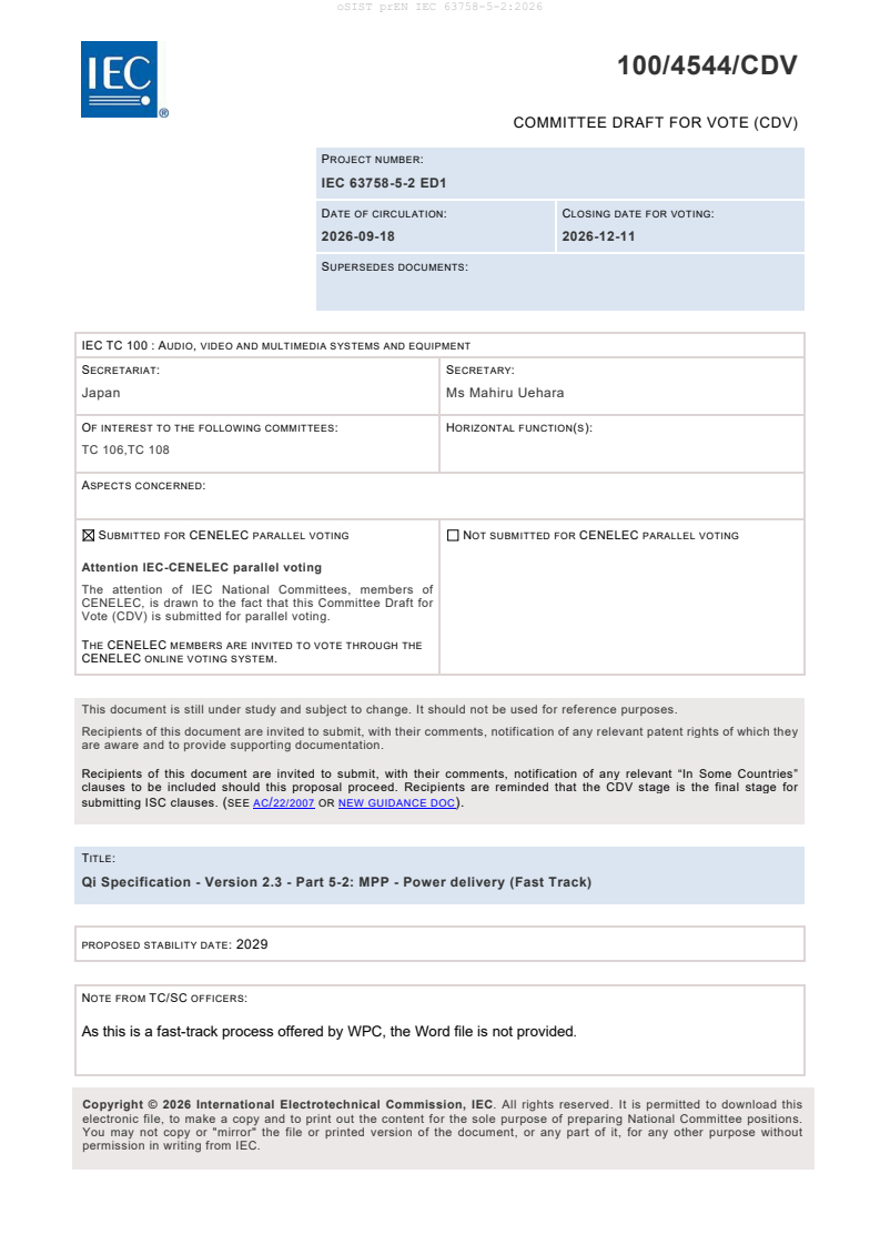
100/4544/CDV
COMMITTEE DRAFT FOR VOTE (CDV)
PROJECT NUMBER:
IEC 63758-5-2 ED1
DATE OF CIRCULATION: CLOSING DATE FOR VOTING:
2026-09-18 2026-12-11
SUPERSEDES DOCUMENTS:
IEC TC 100 : AUDIO, VIDEO AND MULTIMEDIA SYSTEMS AND EQUIPMENT
SECRETARIAT: SECRETARY:
Japan Ms Mahiru Uehara
OF INTEREST TO THE FOLLOWING COMMITTEES: HORIZONTAL FUNCTION(S):
TC 106,TC 108
ASPECTS CONCERNED:
SUBMITTED FOR CENELEC PARALLEL VOTING NOT SUBMITTED FOR CENELEC PARALLEL VOTING
Attention IEC-CENELEC parallel voting
The attention of IEC National Committees, members of
CENELEC, is drawn to the fact that this Committee Draft for
Vote (CDV) is submitted for parallel voting.
THE CENELEC MEMBERS ARE INVITED TO VOTE THROUGH THE
CENELEC ONLINE VOTING SYSTEM.
This document is still under study and subject to change. It should not be used for reference purposes.
Recipients of this document are invited to submit, with their comments, notification of any relevant patent rights of which they
are aware and to provide supporting documentation.
Recipients of this document are invited to submit, with their comments, notification of any relevant “In Some Countries”
clauses to be included should this proposal proceed. Recipients are reminded that the CDV stage is the final stage for
submitting ISC clauses. (SEE AC/22/2007 OR NEW GUIDANCE DOC).
TITLE:
Qi Specification - Version 2.3 - Part 5-2: MPP - Power delivery (Fast Track)
PROPOSED STABILITY DATE: 2029
NOTE FROM TC/SC OFFICERS:
As this is a fast-track process offered by WPC, the Word file is not provided.
electronic file, to make a copy and to print out the content for the sole purpose of preparing National Committee positions.
You may not copy or "mirror" the file or printed version of the document, or any part of it, for any other purpose without
permission in writing from IEC.
QiSpecification
MPP–PowerDelivery
Version2.3
PublishDate:08December2025
DISCLAIMER
Theinformationcontainedhereinisbelievedtobeaccurateasofthedateofpublication,butisprovided“asis”andmay
containerrors.TheWirelessPowerConsortiummakesnowarranty,expressorimplied,withrespecttothisdocument
anditscontents,includinganywarrantyoftitle,ownership,merchantability,orfitnessforaparticularuseorpurpose.
NeithertheWirelessPowerConsortium,noranymemberoftheWirelessPowerConsortiumwillbeliableforerrorsin
thisdocumentorforanydamages,includingindirectorconsequential,fromuseoforrelianceontheaccuracyofthis
document.Foranyfurtherexplanationofthecontentsofthisdocument,orincaseofanyperceivedinconsistencyor
ambiguityofinterpretation,contact:info@wirelesspowerconsortium.com.
Contents
1. General 8
1.1 StructureoftheQi Specification 8
1.2 Scope 9
1.3 Compliance 9
1.4 References 9
1.5 Conventions 10
1.5.1 Notationofnumbers 10
1.5.2 Tolerances 10
1.5.3 Fieldsinadatapacket 10
1.5.4 Notationoftextstrings 11
1.5.5 Short-handnotationfordatapackets 11
2. PowerDelivery 12
2.1 PowerProfiles(BPP+MPP) 12
2.1.1 Specifications 12
2.1.2 Recommendations 13
2.1.3 SpecificationNotes 13
3. PowerModes 15
3.1 SystemModel 15
3.1.1 Reasonsforhavingmultiplepowermodes 15
3.1.2 Powermodesinthesystemmodel 15
3.1.3 Transitionamongpowermodes 19
3.1.4 AdapterVoltageTransitionswithPowerRemovalduringTransitions 21
3.2 Specifications 23
3.2.1 PowerModesSpec1 23
3.2.2 PowerModesSpec2 23
3.2.3 PowerModeSpec3(MPP25PTxonly) 23
3.2.4 PowerModesSpec4 23
3.2.5 PowerModesSpec5 23
3.2.6 PowerModesSpec6 23
3.2.7 PowerModesSpec7 23
3.2.8 PowerModesSpec8 23
3.2.9 SpecificationNotes 24
3.3 DesignConsiderations 25
3.3.1 PTxthatdoesnotrequirepowerremovalformodetransition 25
3.3.2 ProvidinginformationintheMODEXCAPdatapacket 27
4. PowerReceiverFunctionalBlockDiagram 28
4.1 SystemModel 28
4.1.1 SystemmodelPRxcircuittopology 28
4.1.2 SystemmodelPRxresonancetuninginBPPmode 29
4.1.3 SystemmodelresonancetuninginMPPmode(DefaultPowerMode,Low-Power
Mode,andNominalPowerMode) 30
4.1.4 SystemmodelresonancetuninginMPP(HighPowerMode) 35
4.1.5 CRXswitchalgorithm 35
4.1.6 PRxelectricalproperties 38
4.1.7 SystemmodelPRxVRECTsetting 38
5. PowerTransmitterFunctionalBlockDiagram 40
5.1 SystemModel 40
5.1.1 Definitionofinverterphaseθ 41
5.1.2 DefinitionofinverterdutycycleD 41
5.1.3 PTxresonantcapacitorselection 42
5.1.4 PTxcapacitorselectionalgorithm 42
5.1.5 PTxelectricalproperties 47
5.2 MitigatingfalseOVPtriggeringduringCTXswitching 49
5.2.1 TSGC001 49
5.2.2 REC/TSGC001 49
5.2.3 REC/RSGC001 49
5.2.4 REC/RSGC002 49
6. OperatingFrequency 50
6.1 SystemModel 50
6.2 Specifications 50
6.2.1 PTxFrequencySpec1 50
6.2.2 PTxFrequencySpec2 50
6.2.3 PTxFrequencySpec3 50
6.2.4 PRxFrequencySpec4 50
7. ObjectDetection 51
7.1 SystemModel 51
7.2 Specifications 51
7.2.1 PRxQDeflectionSpec1 51
8. DigitalPings128kHz/360kHz 52
8.1 SystemModel 52
8.1.1 NeedForDigitalPings128kHz/360kHz 52
8.1.2 PhasesinDigitalPings128kHz/360kHz 52
8.1.3 OverallFlow 53
8.1.4 IdentificationSequence 56
8.1.5 InverterConfigurations 58
8.2 Specifications 59
8.2.1 PTxDigitalPingSpecifications 59
8.2.2 PTxDigitalPingSpecifications-128kHzPingHB_Low 59
8.2.3 PTxDigitalPingSpecifications-360kHzPing 59
8.2.4 (Optional)PTxDigitalPingSpecifications–128kHzPingHPM 60
8.2.5 PTxDigitalPingRecommendations 61
8.2.6 PTxDigitalPingRecommendations-128kHzPingHB_High(informative) 62
8.2.7 PTxDigitalPingRecommendations-128kHzPingFB(informative) 63
8.2.8 PTxDigitalPingRecommendations-128_HPM 63
8.2.9 PTxDigitalPingRecommendations-360_LPM 64
8.2.10 PTxDigitalPingRecommendations-360_NPM 65
8.2.11 PTxDigitalPingRecommendations-360_HPM 65
8.2.12 PRxDigitalPingSpecifications 66
9. KEstimation 67
9.1 SystemModel 67
9.1.1 NeedForKEstimation 67
9.1.2 KESTCalculationFormula 68
9.1.3 Eco-systemScaling 69
9.1.4 CoefficientsforKESTConductedduringthe128_HPMDigitalPing 70
9.1.5 Errorstack-up 70
9.2 Specifications 71
9.2.1 PTxKESTSpec1 71
9.2.2 PTxKESTSpec2 71
9.2.3 PTxKESTSpec3 71
9.2.4 PTxKESTSpec4 71
9.2.5 PTxKESTSpec5 71
9.2.6 PTxKESTSpec6 71
9.2.7 PTxKESTSpec7 71
9.2.8 PTxKEST Spec8(MPP25PTxonly) 71
9.2.9 PTxKESTSpec9 72
9.2.10 PTxKESTRecommendation2 72
9.2.11 PTxKESTRecommendation3 72
9.2.12 PTxKESTRecommendation4 72
9.2.13 PTxKESTRecommendation5 72
9.2.14 PTxKESTRecommendation6 72
9.2.15 PRxKESTSpec1 73
9.2.16 PRxKESTSpec2 73
9.2.17 PRxKESTSpec3 73
9.2.18 PRxKESTSpec4 73
9.2.19 PRxKESTSpec5 73
9.2.20 PRxKEST Spec6(MPP25PRxonly) 73
10. OutputImpedanceandLoadTransients 74
10.1 SystemModel 74
10.1.1 SlopeoftheoutputImpedance 74
10.1.2 Worst-caseteststomeasuretheslopeoftheoutputimpedance 75
11. GainMeasurement 77
11.1 Background 77
11.2 SystemModel 77
11.2.1 TheoryofOperation 77
11.2.2 PRxballastcurrent 79
11.2.3 GainMeasurementFlowinDefaultPowerMode 80
11.2.4 GainMeasurementFlowinNominal-PowerandHigh-PowerModes 84
11.3 PTxSpecifications 90
11.3.1 PTxGainMeasurementSpec1 90
11.3.2 PTxGainMeasurementSpec2 90
11.3.3 PTxGainMeasurementSpec3 90
11.3.4 PTxGainMeasurementSpec4 90
11.4 PTxSpecificationNotes 90
11.4.1 EquivalentVinv 90
11.5 DesignConsiderations 90
11.5.1 DesignConsiderationsforotherPRxArchitectures 90
11.5.2 DetermineGC0andGC1 91
11.5.3 GainMeasurementintheContinuousPowerMode 92
12. PowerTransferControl 93
12.1 IntroandBackground(Informative) 93
12.2 SystemModel 93
12.2.1 BackgroundandAssumptions 93
12.2.2 Vrect_targetLoop(PRx+PTx) 96
12.2.3 IlimLoop(PRx) 104
12.2.4 Powerthrottling 106
12.3 End-to-EndControlSpecifications 107
12.3.1 Background 107
12.3.2 PTxSpecifications 107
12.3.3 PTxGainLinearizationSpec1 107
12.3.4 PRxSpecifications 110
12.3.5 PRxRecommendations 110
12.3.6 PRxSpecificationNotes 111
12.3.7 DesignConsiderations 112
13. MitigationofSideEffectsofCdatMPPFrequency 113
13.1 SystemModel 113
13.1.1 Non-monotonicVRECT/phaseresponseandoutputimpedanceatlightload 113
13.1.2 Receiverover-voltageprotection 116
13.2 Specifications 117
13.2.1 PTxOCPSpec1 117
14. Over-voltageProtectioninPRx 118
14.1 Introduction 118
14.2 OVPRecoveryFlow(Informative) 122
14.3 OVPRecoveryTimeAnalysis 124
14.4 MaxVRECTAnalysis 124
14.4.1 LoadDumpProcedure 125
14.5 ReducingVRECTOVPRisks(Informative) 126
14.6 Requirements 127
14.6.1 PTxOVPSpec1 127
14.6.2 PTxOVPFastRecoverySpec1 127
14.7 Recommendations 127
14.7.1 PTxOVPRecommendation1 127
14.7.2 PRxOVPRecommendation1 128
14.7.3 PRxOVPFastRecoveryRecommendation1 128
15. Cloak 129
16. Common-modeNoise 130
17. GGValueDefinitions 131
17.1 KESTcoefficients 131
1. General
TheWirelessPowerConsortium(WPC)isaworldwideorganizationthataimstodevelopandpromoteglobalstandards
forwirelesspowertransferinvariousapplicationareas.Animportantapplicationareacomprisesflat-surfacedevices
suchasmobilephonesandchargersoperatingatpowerlevelsupto25W.
1.1 StructureoftheQi Specification
Generaldocuments
l
Introduction
l
Glossary,Acronyms,andSymbols
l
TechnicalSystemOverview
l
PowerProfiles
Systemdescriptiondocuments
l
Mechanical,Thermal,andUserInterface
l
PowerDelivery
l
CommunicationsPhysicalLayer
l
CommunicationsProtocol
l
ForeignObjectDetection
l
NFCTagProtection
l
AuthenticationProtocol
l
MPPCommunicationsProtocol
l
MPPMagneticsDesign
l
MPP PowerDelivery
l
MPP CommunicationsPhysicalLayer
l
MPP ForeignObjectDetection
l
MPP DesignGuidelines(Informative)
l
MagneticCovers
l
ActiveAlignmentSystem
l
ThermalManagementProtocol
1.2 Scope
TheQiSpecification,MPPPowerDelivery(thisdocument)comprisesguidelinesandrequirementsforPowerReceiver
design,includingcircuitry,powerconsumption,operatingpowerlevels,powertransferefficiency,andstandbypower.
1.3 Compliance
AllprovisionsintheQiSpecificationaremandatory,unlessspecificallyindicatedasrecommended,optional,note,
example,orinformative.VerbalexpressionofprovisionsinthisSpecificationfollowtherulesprovidedinISO/IEC
Directives,Part2.
Table1-Verbalformsforexpressionsofprovisions
Provision Verbalform
requirement “shall”or“shallnot”
recommendation “should”or“shouldnot”
permission “may”or“maynot”
capability “can”or“cannot”
1.4 References
Forundatedreferences,themostrecentlypublisheddocumentapplies.ThemostrecentWPCpublicationscanbe
downloadedfromhttp://www.wirelesspowerconsortium.com.
1.5 Conventions
1.5.1 Notationofnumbers
l
Realnumbersusethedigits0to9,adecimalpoint,andoptionallyanexponentialpart.
l
Integernumbersindecimalnotationusethedigits0to9.
l
Integernumbersinhexadecimalnotationusethehexadecimaldigits0to9andAtoF,andareprefixedby"0x"
unlessexplicitlyindicatedotherwise.
l
SinglebitvaluesusethewordsZEROandONE.
1.5.2 Tolerances
Unlessindicatedotherwise,allnumericvaluesintheQiSpecificationareexactlyasspecifiedanddonothaveany
impliedtolerance.
1.5.3 Fieldsinadatapacket
Anumericvaluestoredinafieldofadatapacketusesabig-endianformat.Bitsthataremoresignificantarestoredata
lowerbyteoffsetthanbitsthatarelesssignificant.Table2andFigure1provideexamplesoftheinterpretationofsuch
fields.
Table2-Exampleoffieldsinadatapacket(table)
b b b b b b b b
7 6 5 4 3 2 1 0
B (msb)
B 16-bitNumericDataField (lsb)
B OtherField
(msb)
B 16-bitNumericDataField (lsb)
Field
Figure1-Examplesoffieldsinadatapacket
1.5.4 Notationoftextstrings
TextstringsconsistofasequenceofprintableASCIIcharacters(i.e.intherangeof0x20to0x7E)enclosedindouble
quotes(").Textstringsarestoredinfieldsofdatastructureswiththefirstcharacterofthestringatthelowestbyte
offset,andarepaddedwithASCIINUL(0x00)characterstotheendofthefieldwherenecessary.
EXAMPLE: Thetextstring“WPC”isstoredinasix-bytefieldsasthesequenceofcharacters'W','P','C',NUL,NUL,and
NUL.Thetextstring“M:4D3A”isstoredinasix-bytefieldasthesequence'M',':','4','D','3',and'A'.
1.5.5 Short-handnotationfordatapackets
Inmanyinstances,theQiSpecificationreferstoadatapacketusingthefollowingshorthandnotation:
/
Inthisnotation,referstothedatapacket'smnemonicdefinedintheQiSpecification,Communications
Protocol,andreferstoaparticularvalueinafieldofthedatapacket.Thedefinitionsofthedatapacketsin
theQiSpecification,CommunicationsProtocol,listthemeaningsofthemodifiers.
Forexample,EPT/ccreferstoanEndPowerTransferdatapackethavingitsEndPowerTransfercodefieldsetto0x01.
2. PowerDelivery
Unlessotherwisestated,allcontentsinthisbookapplytopowerdeliveryinMPPmodeinsteadofBPPmode.
2.1 PowerProfiles(BPP+MPP)
2.1.1 Specifications
2.1.1.1 PowerDeliverySpec1
ThePTxshallprovideaBPPPRxwithatleast5Wofrectifiedpowerforr≤8mm,z≤3mm(Figure3).
NOTE:SeeSection2.1.3.1,Definitionofrandz forthedefinitionofrandz.
2.1.1.2 PowerDeliverySpec2
UnlessthePTxoperatesinMPPRestrictedMode,itshallhavethecapabilitytoprovideanMPPPRxwithatleast15W
ofrectifiedpowerinsidethe2x2cylinder(r≤2mm,z≤2mm)Figure2.
2.1.1.3 PowerDeliverySpec3
ThePTxshallprovideanMPPPRxwithatleast5Wofrectifiedpowerforr≤4mm,z≤3mm.
2.1.1.4 PowerDeliverySpec4
ThePTxshallprovideanMPPPRxinrestrictedmodeamaximumof6.5WreceivedpowerinMPPRestrictedmode.
ThisisbasedonBPPsystemspecification.
2.1.1.5 PowerDeliverySpec5( MPP25PTxOnly)
ThePTxshallprovideTPR#MPP4withatleast25Wofrectifiedpowerforr=0mm,z≤2mm.
2.1.1.6 PowerDeliverySpec6(MPP25 PTxOnly)
ThePTxthathasaVinlessthanorequalto20VshallhaveaVinv-VRECTRatioofatleast0.95withTPR#MPP4at
position(0,2).
NOTE:ThePTxdesignshouldensurethatthisrequirementissatisfiedusingitslowestCTXtoensurethehighestVRECT-Vinvratio.
PleaseseeSection3.2.9,SpecificationNotes forthedefinitionofsupporting25WandVinv-VRECTRatio.
2.1.1.7 PowerDeliverySpec7(MPP25PRxOnly)
ThePRxshallhaveaVinv-VRECTRatioofatleast0.95withTPT#MPP4atposition(0,2).
PleaseseeSection3.2.9,SpecificationNotes forthedefinitionofVinv-VRECTRatio.
2.1.1.8 PowerDeliverySpec8
WhenpairedwithaTPR,thePTxshalldeliveritsECAP[PotentialLoadPower]continuouslyforatleast150seconds
withoutthrottling.
2.1.2 Recommendations
2.1.2.1 PowerCapabilityReductionRecommendation1
InMPPmode;Forz>3mm&r>4mm,loadpowerdeliveryshouldgraduallydecreasefrom5Wasthedistanceand
heightfromthecentreincreases.
2.1.2.2 PowerCapabilityReductionRecommendation2(MPP25PTxOnly)
ThePTxmaygraduallydecreaseitsloadpowerdeliveryfromatleast25Wtoatleast15Wfor0
2.1.3 SpecificationNotes
2.1.3.1 Definitionofrandz
MPPdevicesarerequiredtoprovideguaranteedperformancewithrespecttoexternallyobservablefeaturesofthe
designsuchasdistancebetweenthecontactsurfaceofPTxtothecontactsurfaceofthePRx.Thus,inthespecified
powerdeliveryvolumebelowandthroughouttheMPPspecification,when"z"distanceisspecifieditindicatessurface-
to-surfaceseparationratherthan,forinstance,thecoil-to-coilseparation.
Forexample,Figure4showshowzgapbetweenaPTxandPRxisdefinedinthesystemmodel.Inthisexample,thePTx
andPRxhavethesamemechanicalstack-upasdiscussedintheMPPMagneticsDesignbook.
Theoriginr=0isdefinedasthelocationcorrespondingtomaximumcouplingwhenz=0.
Figure2- Forr=0mm,z≤2mm,a25WMPPPTxshallbeabletodeliveratleast25W.
Figure3-AnMPPPTxshallbeabletodeliveratleast5WtoanBPPsystemmodelPRxforr≤ 8mm,z≤3
mm
Figure4-Crosssectionviewofthesystemmodelindicatingthe"z"gap.
3. PowerModes
3.1 SystemModel
3.1.1 Reasonsforhavingmultiplepowermodes
Optimizingpowerdeliveryatdifferentpowerlevelscanleadtodifferentdesigndecisions.Inordertosupportpower
deliveryupto25W,thesystemmodelemploysdifferentpowermodesdependingonpowerlevels.Thisallowsthe
systemmodeltousethebesthardwareandalgorithmicstrategyforeachpowerlevel.
Apowermodeisasystemoptimizationforefficiencywithinaparticularpowerrange(seeTable3).Thefollowing
powermodesaredefined:
l
DefaultPowerMode(DPM):Themodeinwhichthesystemoperatesifeitherofthematedproductsreportv2.1
orlower.
l
LowPowerMode(LPM)/NominalPowerMode(NPM)/HighPowerMode(HPM):Thesemodesare
designedforusewithpowertransmittersthatoperatefromareconfigurablepowersupply(suchasaUSB-PD
adapter).
l
ContinuousPowerMode(CPM):Thismodeisdesignedforusewithpowertransmittersthatoperatefroma
fixedpowersupply(suchaswithinanautomotiveenvironment).
Categoricallyspeaking,thedesignconsiderationsbehinddifferentpowermodesinthesystemmodelare:
l
Voltagerange:Generally,lowerpowerlevelneedslowerinputvoltagetothePTxinverterandloweroutput
voltageatthePRxrectifier.Thishelpstocontroltheeffectivecurrentandimpedanceofthematedsystemand
containefficiencywithinadesiredrange.
l
Inthesystemmodel,theinputvoltagetothePTxinverteriscontrolledbyaboostconverter(SeeFigure
7).Therefore,alowerinputvoltagetothePTxinverterleadstoalowerinputvoltagetotheboost
converter(i.e.,adaptervoltage).
l
EMI:Therearetwoscenarioswheretherearehigherradiationrisks:
l
WhenthePTxinverterisinphaseorduty-cyclecontrolmode(seeSection6.1,SystemModel),the
switchingwaveformshavemorehigh-harmonicdistortions.Thisusuallyhappensatlowpowerrange.
l
WhenthePTxinverterlosesZVS(zero-voltageswitching)operation,theinvertermayhavesharp
switches.EnsuringZVSgenerallyrequiresinductiveload,andsinceeffectiveloadchangeswithpower
level,thesystemmodelneedsdifferentcapacitortuningstrategies.
l
Controlresolutionandrange:Thecircuitgain(seeSection12.2.2.3,PTxControl)varieswithpower,resultingin
controlinstabilityorinsufficientdynamicrange,ifnotcontained.Thesystemmodelusesdifferentresonant
capacitors,targetVRECTvoltages,andadaptervoltagestounifythegainasmuchaspossibleatdifferentpower
levels.
Withthesedesignconsiderations,Section3.1.2,Powermodesinthesystemmodel explainsthepowermodesemployedin
thesystemmodel.
3.1.2 Powermodesinthesystemmodel
Thesystemmodeldividespowerlevelsintolow,medium,andhigh,thusresultinginthreepowermodes:lowpower
mode,nominalmode,andhigh-powermode.
Additionally,thesystemmodelutilizesa"DefaultPowerMode".IfthesystemmodelPTxandPRxagreetobeinthis
mode,theyoperateinawaythatisbackwardscompatiblewithproductscertifiedtopreviousversionsoftheQi
Specification.
Thefollowingtablesummarizesthepowermodesanddesignparametersassociatedwitheachmode.Thesedesign
choicesareexplainedindetailintheirrespectivesections,asannotatedinthetable.SeeSection3.3,Design
Considerations forexamplesofothersystems.
Table3-PowerModesinthesystemmodel
Low
DefaultPower NominalPower HighPower ContinuousPower
Power
Optimized N/A Upto5 4.5W-20W 12-25W Upto25W
Power W
Level
(approx.)
(seeFigure
5)
Adapter 9V 5V 9V 15V ≥9V
voltage
(seeSection
3.1.4,
Adapter
Voltage
Transitions
withPower
Removal
during
Transitions
)
l
CTXtuning Initializedto: 101nFwhen
(360kHz)
l
101nFwhen 458nFwhen
l
(seeSection
l
5.1.3,PTx 68nFwhen
68nFwhen
l
resonant
capacitor l
134nFwhen
selection)
Dynamicallycontrolled
afterinitialization
Low
DefaultPower NominalPower HighPower ContinuousPower
Power
CRXtuning Fixedat710nF Initializedto710nF,
(360kHz) thendynamically
l
Initializedto710nF
(seeSection
controlledbasedon
l
Dynamicallycontrolledbasedonpower
4.1.3,
powerlevel,after
level,afterinitialization
System initialization
model
resonance
tuningin
MPPmode
(Default
Power
Mode,Low-
Power
Mode,and
Nominal
Power
Mode) and
Section
4.1.4,
System
model
resonance
tuningin
MPP(High
Power
Mode))
l l
Vinrange 11V-18V 6.5V- 10V–18V 16V-20V 6.5V-23V
(seeSection
(low-k 18V (low-k
12,Power
mode) mode)
Transfer
l l
MPT#1:11 10V–20V
Control)
V-19V (otherwise)
(otherwise)
l
MPT#2:11
V-25V
θrange 0°-50° 0° 0°-50° 0°-50° 0°
(seeSection
12,Power
Transfer
Control)
VRECT Switchbetween 12.5V Dynamic,between 18V Dynamic,between
target 12Vand14V 12.5Vand18V 12.5Vand19V
(seeSection
withhysteresis
4.1.7,
System
modelPRx
VRECT
setting)
NOTE:Somedesignparametersinthistableare“approximations”,becauseofhysteresisorothercornerconditions.Pleasereferto
eachspecificsectionfortheexactvaluesandconditions.
NOTE:Someimplementationsmayonlyuseasinglepowermode,e.g.continuouspowermode.SeeSection3.3,Design
Considerations forfurtherdetails.
3.1.3 Transitionamongpowermodes
PRxisthesidewhodetermineswhichpowermodethewirelesspowertransfershouldbeunder.Themainreasonis
becausePRxknowspowerrequirementsasithasdirectaccesstotheloadpower.
Figure5describeshowthesystem-modelPRxtransitsamongdifferentpowermodes.Specifically:
l ThePRxstartswithnominalpowermodeorhigh-powermodedependingontheestimatedcoupling (See
Section9,KEstimation);
l
AfterSetPr_max(Section11,GainMeasurement),thePRxshiftstonominalmodeiftheestimatedG3istoosmall;
l
Duringpowertransfer,transitionsbetweenmodesarebasedonobservedloadpower.Therearetwotypesof
transitions:
l
“fast”transitionsareusedtotriggerpowermodetransitionsbasedonfastPRECTchanges(t_high_fastand
t_low_fastinTable4);
l
“slow”transitionsareusedtotriggerpowermodetransitionsbasedongradualPRECTchanges(t_high_
slowandt_low_slowinTable4)
l
Onceinnominal-powermode,thesystemmodelPRxdoesnottransittohigh-powermodeuntilpoweris
removedwhenthePRxsendseitheranEPTorCLOAK datapacket.
TheparametervaluesusedinFigure5arespecifiedinTable4.
Figure5-TransitionbetweenPowerModes
Table4- TransitionbetweenPowerModes(Parameters)
Symbol Value
Kest_th_hpp 0.657
G_th_hpp 0.98
P_th_high_fast 12W
t_high_fast 3seconds
P_th_low_fast 2.5W
t_low_fast 4seconds
P_th_low_slow 4W
t_low_slow 40seconds
P_th_high_slow 4.5W
t_high_slow 40seconds
current_limit_mode ABooleanflagindicatingthattheloadcurrentmeetstheloadcurrentlimit(seeSection
12.2.3.1,LoadCurrentControl)
InpracticalPRxdesigns,Figure5isdesignedforthescenariowheretheVRECTofPRxisnottiedtobatteryvoltage(for
example,oneswithabuckconverter).ForthePRxwhoseVRECTistiedtobatteryvoltage,pleaseseeanexamplein4.
3.1.4 AdapterVoltageTransitionswithPowerRemovalduringTransitions
PowermodesprovideameansforPTxtoelegantlyswitchamongdifferentpotentialadaptorvoltages(Vadapter).Each
powermodecouldcorrespondtoaVadaptersetting,orasetthereof.Duringpowermodetransitions,PTxcanelectto
rampdownpowertoensuresafeadaptervoltagetransition.
Figure6showsanabstractmodelofaPTxadapterconfigurationthatsupportstwoadaptervoltages,VAandVB.VAand
VBbelongtodifferentpowermodes,andswitchingbetweenthemrequirespowerinterruption.
Figure6-AnabstractmodelofaPTxadapterconfigurationthatrequirespowerinterruptionduringpower
modetransition.
Thesystem-modelPTxisanexampleofsuchconfiguration.Itsupportsthreediscreteadaptervoltages:5V,9Vand15
V.ApracticalexampleofsuchconfigurationisanUSB-CPDcharger.BetweenVadapterandVin,thereisaboost
converter(Figure7).Table5showsthesupportedvoltageofthesystemmodelPTx.
Figure7-SystemmodelPTxinputDC/DCconverter
Table5-VadapterandsupportedVinofthesystem-modelPTx.
Vadapter MinimumSupportedVin MaximumSupportedVin
5V 6.5V 20V
9V 10V 20V
15V 16V 20V
Figure8showsanexampleofhowthesystem-modelPTxperformsadaptervoltagetransitionbeforerampingupto
high-powermode.Inthisexample,weassumethepoweradapter,PTxandPRxallmeetthepowercapacitytooperatea
high-powermode.Thesystem-modelPTx/PRxpairgothroughthefollowingsequence:
l
Vadapterstartsat5V;
l
PTxstartsobjectdetectionanddetectsthepresenceofPRx(seetheFODchapter);
l
PTxnegotiates9V/3Awiththeadapterandobtainsconfirmation;
l
PTxstarts128kHzdigitalping(seeSection8,DigitalPings128kHz/360kHz);
l
Inthenegotiationphase,PRxrequestshigh-powermodeandPTxconfirmsit;
l
SincePTxknowsPRxrequestsforhigh-powermode,PTxnegotiates15Vwiththeadapterandrestartthe
inverterfor360kHzoperation;
l
PTxstarts360kHzdigitalping(seeSection8,DigitalPings128kHz/360kHz);
l
Inthenegotiationphase,PRxandPTxre-confirmhigh-powermode;
l
ThePTx/PRxpairperformG3measurement(seeSection11.2.3,GainMeasurementFlowinDefaultPowerMode),
thenuseXCEpacketandVRECTtargettoregulatepowerto25W(seeSection12,PowerTransferControl).
RefertotheMPPCommunicationsProtocolbookformoredetails.
Toreducethepowerramp-uptime,theexpectedpowermodemaybeselectedduringthe128kHznegotiationphase.
SincethePTxneedstorebootitsinverterbeforethe360kHzdigitalping,itusesthesameopportunitytonegotiatewith
theadaptertotransittothedesiredvoltageaswell.Bydoingso,thesystem-modelPTxminimizesthenumberof
unnecessarypowerdisturbancetoPRx.
Figure8-Exampleflowforsystem-modelPTxwithaUSB-CPDadaptertoperformadaptervoltagetransition
duringramp-uptohigh-powermode.
3.2 Specifications
3.2.1 PowerModesSpec1
Foreachsupportedpowermode,thePTxshallbeabletoprovideTPR#MPP4withthedeclaredpotentialpowerinits
advertisedMODEXCAPdatapacketwithinr=0mm.0mm≤z≤2mm.
3.2.2 PowerModesSpec2
ThePTxshalladvertiseapotentialpowerofatleast15WforatleastoneofthepowermodesitlistsintheMODEXCAP
datapacket.
3.2.3 PowerModeSpec3(MPP25PTxonly)
ThePTxshalladvertiseapotentialpowerofatleast25WforatleastoneofthepowermodesitlistsintheMODEXCAP
datapacket.
3.2.4 PowerModesSpec4
ForPTxsusingdiscretepowermodes,thePTxshalladvertisepotentialloadpowersuchthat"HPMPotentialLoad
Power">"NPMPotentialLoadPower">"LPMPotentialLoadPower."
3.2.5 PowerModesSpec5
ThePTxshallsupportallthepowermodesbelowthehighestadvertiseddiscretepowermode(LPM,NPM,HPM).
3.2.6 PowerModesSpec6
ForPTx'susingdiscretepowermodes,thePTxshalladvertiseoverlapping"VoltageRef0"and"VoltageRef1"inthe
MODEXCAPdatapacketforeachsupportedpowermodesuchthat:
l
LPMVoltageRef1≥NPMVoltageRef0
l
NPMVoltageRef1≥HPMVoltageRef0
NOTE:IfVoltageRef0andVoltageRef1aresetto0thenthatcorrespondingpowermodeisnotsupported
3.2.7 PowerModesSpec7
APTxthatsupportsCPMshallnotsupportanyofthediscretepowermodes(LPM,NPM,HPM).
3.2.8 PowerModesSpec8
PTxshallsupportLPMwithapotentialloadpowerofnomorethan10W.
3.2.9 SpecificationNotes
1. RelaxedVolume:ComparedwithPowerprofilespecifications(Section2.1.1,Specifications),Powermode
specificationsusearelaxedvolumeforguaranteedpower:insteadofthe2x2cylinder,thepowermode
specificationsarerequiredforalinesegmentof0mm≤z≤2mmonther=0mmaxis,forthereasonsbelow:
l
High-powermodedeliveryisanenhanceduserexperience,butahigherpowerlevelimposeschallenges
especiallywhenthecouplingislow.Therefore,itmakessensetoguaranteethisuserexperiencewitha
smallerLQKspacewithstrongcouplings.
l
zheightismoreimportantthanrtoallowforpotentialaccessoriesinbetween.
2. DefinitionofVinv-VRECTRatio:Vinv-VRECTratioofaPTx-PRxpairisdefinedastheratiobetweenVRECTand
Vinv,whenthePRxoperatesataconditionwith
Asdemonstratedin Figure9,thereisastrongcorrelationbetweenVinv-VRECTandachievablePRECT,especially
around25W.Therefore,theVinv-VRECTratioisadependablecharacteristicoftheelectricalandmagnetic
propertiesofthePTxorPRxdevicethatcanbeusedtopredictthepowercapacityofthesaiddevice.
Figure9-StrongCorrelationbetweenPRECTandVinv-VRECTRatio
Monte-Carlosimulationswererunacrossthemagneticboundaryandkeycomponenttolerances(e.g.,CTXandCRX).The
Y-axisisthemaximumpossiblePRECTwhenPTxreachesitsmaximuminverterdriveandifthereisnomaximum
powerlimit.TheX-axisistheobservedVinv-VRECTratioinsimulation.
3.3 DesignConsiderations
3.3.1 PTxthatdoesnotrequirepowerremovalformodetransition
NotallPTxdeviceshavediscreteadaptervoltagesandVinrangesthatrequirepowerinterruptionduringpowermode
transitions.Forexample,aPTxmountedinsideanautomobilemayhaveasinglecontinuousVinrangethatcansupport
allthewayupto25W.RefertotheMPP DesignGuidelines(Informative)bookforsomeexamples.
Figure10-Examplesofpossibleadapterandconvertercombinationsthatmaysupportasingle,continuous
Vinrange
ThereareafewdesignconsiderationsforthesePTxdevices:
l
ThePTxmanufacturercandecidetosupportasinglemode,e.g.,continuouspowermode,forthewholepower
rangeupto25W.ItcouldelecttoadvocatetoPRxthatneitherlow-powermodenornominal-powermodeis
supported.
l
ThePTxmanufacturercanalternativelydecidetosupportmultiplemodes,butwithnopowerremovalduring
powermodetransition.
l
ThePTxdoesnothavetofollowthesystem-modelVinranges(Table3).Forexample,inthesystem-modelPTx,
thelowerlimitofVininhigh-powermodeis16V(seeTable3.).ThiscouldposelimitationstoPRxdevicesthat
usesswitched-capconverters,whichhaveamuchlargerdynamicrangeofVRECTthanthesystemmodelPRx
(Section4,PowerReceiverFunctionalBlockDiagram).ThePTxcanchoosetosupportalowerlimit,forexample,
12.5V.
DependingonthecharacteristicsofthePTxandPRx,manufacturersshouldreachtheirowndecisionsonwhatpower
mode(s)tosupport,andtheircorrespondingoperatingranges.Table6andTable7providetwoexamples.
Inthefirstexample,wehave:
1. aPTxdesignthatissuppliedbyacarbattery,usesabuck-boostconverter,andsupportsonlyonepowermode,
and
2. aPRxdesignthatusesswitched-capconverter
Table6-PowerModesExample1
ContinuousPowerMode
OptimizedPowerLevel N/A
AdapterVoltage 12.6V-14.4V
CTXtuning dynamicallyswitched
CRXtuning Initializeto710nF(anddynamicallycontrolwhennecessary)
Vinrange 0-23V
θrange 0°
VRECTtarget RefertotheMPP DesignGuidelines(Informative)book.
Inthisexample,wehave:
1. aPTxdesignthatissuppliedbyacarbattery,usesabuck-boostconverter,andsupportstwopowermodeswith
nopowerremovalatpowermodetransition,and
2. aPRxdesignthatusesswitched-capconverter
Table7-PowerModesExample2
NominalPowerMode HighPowerMode
OptimizedPowerLevel 0-15W 15W-25W
AdapterVoltage 12.6V-14.4V
CTXtuning Fixed. Dynamicallyswitched
l
101nFwhen
l
68nFwhen
CRXtuning Dynamicallyswitched Dynamicallyswitched
Vinrange 0-23V 12.5V-23V
θrange 0°
VRECTtarget RefertotheMPP DesignGuidelines(Informative)book.
3.3.2 ProvidinginformationintheMODEXCAPdatapacket
Duringnegotiation,thePTxprovidesareferenceVRECTrangeassociatedwitheachpowermode,throughMODEXCAP
packet.ThereferenceVRECTrange,say,(Vrect_ptx_min,Vrect_ptx_max),istheVRECTachievableatTPR#MPP4while
deliveringthepowerspecifiedbytherelevantPowerModePotentialLoadPower.ThePRxcanusethisinformationto
approximatelyconvertthisreferenceVRECTtoitsownVRECTifpairedwiththePTx,andselectwhetheritshouldstart
withNPMorHPMmode.Belowisanexampleofsuchconversionmethods:
l
ThePTxpairsitselfwithaTPRandmeasuresitsreferenceVRECTrangeunderthesameloadcurrent:(Vrect_prx_
min,Vrect_prx_max)
l
TheTPT/TPRpairprovidesa"golden"referenceVRECTrangewhentheyarepaired:(Vrect_tp_min,Vrect_tp_
max)
l
ThePRxcanapproximateitsVRECTrangewiththefixedloadcurrentwhenpairedwithaPTxas:(Vrect_ptx_min
*Vrect_prx_min/Vrect_tp_min,Vrect_ptx_max*Vrect_prx_max/Vrect_tp_max)
Duringpowertransfer,sometimesthePTxmaydesireamodechange,eithersuggestiveorassertive.
l
Suggestion:UsetheMSN datapacket
l
Assertion:Forexample,whenpowerdropsinHigh-PowerMode,thePTxcouldenterthephase-controlregion
andtriggerZVS.IfthePTxdecidesthatthisisundesirableorunacceptable,thePTxcanforcePRxtochangethe
powermode,byupdatingitssupportedpowermodeinfo,i.e.,thePTxcouldremoveHPMfromitssupported
powermodes(forcingthePRxtochangepowermode).
l
Assertion:Removethepowersignalimmediatelyandre-ping.
PleaserefertotheMPPCommunicationsProtocolforfurtherdetails.
4. PowerReceiverFunctionalBlockDiagram
4.1 SystemModel
4.1.1 SystemmodelPRxcircuittopology
ThesystemmodelPRxcircuittopologyispresentedinFigure11andinTable8.
DuringdigitalpingandBPPmodeS1isopen.AftertheMPPhandshakethePTxwillturnoffandswitchto360kHz.
WhenthePRxdetects360kHzitwillturnonS1toenterMPPpowerdeliverymode.
ThePRxcomprisesthefollowing:
l
SeriesimpedancetuningnetworkforBPPandMPP
l
Parallelresonantfordetection
l
Idealfull-bridgerectifier
Additionally,thesystemmodelPRxassumesthattheloadhasapowerconverter(e.g.Buckconverter)forconverting
betweentheoptimalVRECTregulationvoltage,tothe4Vbatteryvoltage.Ithasthefollowingproperties:
l
Theinputcurrentlimit(Ilim)iscontrollableandusedtocontrolthemaximumrectifiedpower(seeSection12.2.3,
IlimLoop(PRx)).
l
TheoutputvoltageisregulatedtobatteryvoltagewhenVRECT>4V
Figure11-SystemmodelPRxcircuittopology(withBPPandMPPcompatibility).
Table8-PRxseriestuningconfiguration.
Powertransfer
S1 Transmitterfrequency
mode
open 128kHz 128kHzdigitalping
open 128kHz BPPpowertransfer
closed 360kHz MPP360kHzdigitalping
closed/open 360kHz MPP powerdeliverywhereS1is
dynamicallycontrolled
closed 360kHz MPP DefaultPowerMode
4.1.2 SystemmodelPRxresonancetuninginBPPmode
FollowingthesystemmodelmechanicaldesignintheMPPMagneticsDesignbook,andtheDualResonantCircuitsection
inthePowerDeliverybook, wecantunetheBPPmodecapacitors toseriesresonantfrequency:
PRxcoilinductance,matedwithPTxCoilSystemModelinQifrequencyrange:
=14.6μH
So,theseriesresonantcapacitor is:
=174nF
Inpracticaldesigns,therecommendedtolerancesof and areboth±5%.
Parallelresonantfrequency
PRxcoilinductancewithoutPTxferritepresent(Freeairinductance) :
=9.17μH
So
=2.7nF
Inpracticaldesigns,therecommendedtoleranceof is±0.6μH,and is±10%.
4.1.3 SystemmodelresonancetuninginMPPmode(DefaultPowerMode,Low-PowerMode,and
NominalPowerMode)
FollowingthesystemmodelmechanicaldesignintheMPPMagneticsDesignbook,weselectthePRxresonantcapacitor
tobethefollowingvaluebasedonthematedinductance:
= + =710nF
Notethatthe valueat360kHzMPPmodeishigherthan usedfor128kHzBPPmode(174nF,seeSection4.1.2,
SystemmodelPRxresonancetuninginBPPmode),despitethattheMPPfrequencyishigher.InBPPmode, ischosen
totunethePRxcoiltobeclosetotheresonantpoint;thismethodworksbyminimizingthePRxreactance,andworks
wellwhenthecouplingisrelativelylow.Whenthecouplingishigh,asinthecasewith360kHzMPPmode, needsto
bechosenwith consideringPTxandPRxasawholesystem,insteadofjustPRxinisolation.Thefollowing
subsectionsexplainthemethodologyofhow and valuesareselectedforthesystemmodelinMPPmode.
4.1.3.1 Ruleofthumb
Theruleofthumbinselectingresonantcapacitorat360kHzinthesystemmodelistohaveitsequivalentcapacitance,
includingreflected ,toresonantwiththeleakageinductanceonthePTxside.ConsidertheCantileverequivalent
circuitinFigure12:
Figure12- CantileverEquivalentCircuit.
and shouldbeselectedsothatthe currentbranch(dottedblue)isclosetoresonance.Thetotalequivalent
capacitanceis
Wehavetwodifferentresonantfrequencies:
1. PTxresonantfrequency:
2. Powertransferresonantfrequency:
Andcapacitorscanbechosencorrespondinglytotunetheresonancepoints.
Sincewearetuningtheequivalentcapacitancewithregardtotheleakageinductance,the valuechoseninMPPmode
ishigherthan inBPPmode:theleakageinductanceismuchlowerthantheself-inductance,especiallyathigh
couplinglocations.
Usingtheresonanceequationsonlygiveaninitialsetof and values.Thefinalvaluesusedinthesystemmodelare
chosenwithmuchmorecarefuldesignconsiderations.PleaseseeSection4.1.3.2,Selectionofresonantcapacitors.
4.1.3.2 Selectionofresonantcapacitors
Inthesystemmodel,theresonantcapacitorsareselectedtomeetthefollowingprimarydesigngoals:
l
15Wpowerdeliverywithin2x2cylinder;
l
ZVS(zerovoltageswitching)isguaranteedforlowEMI;
l
Optimizationforefficiency.
Thissectiongivesasummaryofthedesignexerciseleadingtotheselectionofthecapacitorsinthesystemmodel.
Essentially,startingfromthecapacitorvaluesindicatedinSection4.1.3.1,Ruleofthumb,therearethreesteps:
1. FHA(firstharmonicapproximation)toselectinitialcapacitorvalues,
2. Time-domainsweepsofworst-caseoperatingconditionstooptimizethevalues,
3. Practicaldesignconsiderationstofinalizethevalues.
4.1.3.3 FHAanalysis:selectinginitialvaluesofC
t
Thefirststep(FHAanalysis)canbedoneanalytically.Theequivalenttotalinputimpedanceatthetransmittersidecan
bewrittenasin4.
Equation:1
where
l , , , arethematedPTxinductance,PRxinductance,PTxresistanceandPRxresistance,respectively
(seetheGlossarybook )
l isthePRxparallelcapacitor(seeFigure11)
l
istotalmutualimpedance.Withinductivecoupling andresistancecoupling ,
l
istheequivalentACresistanceoftheload.InFHA,assumingtherectifierisincontinuousconductionmode,it
canbeestimatedas
BasedonEquation:1,thesystemgaincanbederived:
Equation:2
Avalidsetofresonantcapacitorvaluesshouldmeetthefollowingcriteriaforallpossiblemagneticparameterswithin
the2x2cylinder:
1. Thephaseof (Equation:1)ishigherthan20degreestoensureZVS
2. Toreachthedesired (14V,seeFigure19)at15W,thegain (Equation:2)shouldbebigenoughsuch
thattheneeded that'slessthanthemaximum(Table13)
Ontopofmeeting1and2,anoptimizedsetofcapacitorvaluesshouldyieldashighefficiencyaspossible.
Theworst-casescenarioofcriteria1and2maybeachievedatdifferentoperatingconditions.Forexample,withall
otherparametersequal,theworst-casescenarioofcriterion1isreachedatmaximum whiletheworst-caseofcriterion
2isreachedatminimum .
Asweepofalloperatingconditionsisthendonetodecidethebestchoiceof and :
l Tuning toPRxcoilresonanceleadstosuboptimal values.Amuchhigher isneeded.Thisisevidentby
lookingattheefficiency(Figure13),Zin(Figure14)andgain(Figure15).Thisconfirmsthefirstprinciples
showninSection4.1.3.1,Ruleofthumb.
l Inthesystemmodel,asingleselectionof isn'tpossibletomeetbothcriteria,sotwodifferent valuesare
useddependingontherangeof .
Figure13showsthatefficiencyislowwhen <300nF(systemiscapacitive).
Figure13- EfficiencyvsCRX:sweepofCRXatthemaximumcouplingpositioninthesystemmodel
Figure14showsthat,with =60nF,thesystemimpedanceiscapacitive,whichisundesirable.
Figure14-BodeplotofZin(s)atmaximumcouplinglocationwithtwodifferentCRXvalues.
Figure15showsthat =710nFhas~1.4dBhighergainthan =60nF.
Figure15-BodeplotofG(s)atmaximumcouplinglocationwithtwodifferentCRXvalues.
4.1.3.4 Time-domainsweep
Oncetherangesofvaluesof and capacitancesaredownselected,time-domainsimulationsareruntofine-tune
thevalues.Time-domainsimulationshelptocaptureharmoniceffectsthatareneglectedinFHA.Thethirdharmonic
frequencyisparticularlyimpactfulsinceitresonateswith ,whichisfurtherexplainedinSection13,MitigationofSide
EffectsofCdatMPPFrequency .
4.1.3.5 Otherdesignconsiderations
Todeterminethefinalvaluesofthesystem-model and capacitance,thereareafewotherdesignconsiderations:
l
With >> ,thetoleranceon isreduced.Theisverybeneficial,asduetospacelimitations,PRxusuallyhas
touselowerqualityX5Rcapacitors(comparedtoC0GcapacitorsinthePTx).
l
Withhigher valueandlower value,ASKmodulationdepthon isincreased.
l Capacitorvaluesareroundedtothecloseststandardvalues.Forexample,thefollowingtableshowshow
valuesarerounded:
Table9-Powertransfertoresonancecapacitors
range Optimalequivalent Finalvalue
≥0.81 100nF 101nF(68nF+33nF)
<0.81 65nF 68nF
4.1.4 SystemmodelresonancetuninginMPP(HighPowerMode)
Inputvoltagedynamicrangeisanewchallenge,inadditiontotheonesdescribedinSection4.1.3,Systemmodel
resonancetuninginMPPmode(DefaultPowerMode,Low-PowerMode,andNominalPowerMode),whenextendingthe
powerlevelofthesystemmodeltobebeyond15W.Inhigh-powermode,thesystemmodelusesa15Vadapterinput
voltage,whichsignificantlyshrinkstheinputvoltagerange,especiallythelowerbound(16V).Thesystemmodelneeds
tocarefullyconstrain (seeEquation:2)sothattheVinvneededtoreachthedesiredVRECTiswithinthe
narrowrangeof16V-20V.
Additionally,thesystemmodelneedstochoosethecapacitorthatguaranteesZVSoperationandyieldsthebest
efficiency.
ByanalyzingG(s)andZin(s),wecanseethefollowinggeneraltrendwithinthesystemmodel’soperatingcondition:
l
AhigherCTXleadsto:
l
smallerG(s)amplitude,thusneedingahigherVinvtoregulatepower
l
moreinductiveZin(s),thuslessZVSrisk
l
AhigherCRXleadsto:
l
smallerG(s)amplitude,thusneedingahigherVinvtoregulatepower
l
moreinductiveZin(s),thuslessZVSrisk
Atthesametime,alowerpowerlevelrunshigherrisksofexhaustinglowerboundofVinvandlosingZVS,thusahigher
CTXandCRXvaluesaredesirable.Therefore,thestrategyofcapacitortuninginMPPhigh-powermodeissummarized
as:
StartingwiththehighestCTXandCRXvalue,dynamicallyswitchtothenextsmallervaluewheneverthecurrentvalue
cannotmeetthepowerdeliverygoal.
ThisstrategyexpandstotheCTXswitchingalgorithminSection5.1.4,PTxcapacitorselectionalgorithm andCRX
switchingalgorithminSection4.1.5,CRXswitchalgorithm.Twoadditionaldesignconsiderationsalsogointothesetwo
algorithms:
l
SwitchingCTXisprioritizedoverswitchingCRX,i.e.,CRXisswitchedonlyifallCTXvalueshavebeenexhausted.
l
AnadditionalCTXvalue(134nF)isaddedtoCTXvaluechoices.Otherwise,thegapbetween458nFand101nF
istoobigtoguaranteeoperationsacrossallpowerlevels.
4.1.5 CRXswitchalgorithm
Asdiscussedabove,innominalpowermodeandhighpowermode,thesystemmodelPRxswitchesCRXdynamically
duringpowertransfer.Specifically,therearetwoCRXvaluestoselectfrom:
l
The“low”value(174nF):requireslowerVinvtodeliverhigherpowerbutwithmoreZVSrisk
l
The“high”value(710nF):haslessZVSriskbutrequireshigherVinvtodeliverpower
Figure16showsthehigh-levelstatediagram.Therearetwokeysubroutines:
l
CheckSwitchToLow(Figure17):duringthestatewhereCRXholdsthehighvalue,thesystemmodelPRx
constantlychecksifitshouldswitchtothelowvalue.
l
CheckSwitchToHigh(Figure18):similarlythesystemmodelPRxchecksifitshouldswitchtothehighvalueifit
holdsthelowvalue.
BothsubroutinesaretriggereduponsendingtheMPLApacket.
Figure16-CRXSwitchingHigh-LevelStateMachine
TheCheckSwitchToLowsubroutineessentiallyperformsthefollowingsequentially,ashighlightedinFigure17:
l
CheckifCRXswitchisallowed:thesystemmodelallowsCRXswitchingifeitherthefollowinghappens:
1. KEST(Section9,KEstimation)islowsothesystemmodelPRxexpectsahighCRXisn’tsufficientto
deliverhighpower;
2. Vinvcontinuouslymaxesout,whichindicatesweneedalowerCRXvalue.ThePRxdetectswhetherVinv
hasmaxedoutviaPTx’sresponsetoXCEpacket.ThisguaranteesthatCTXcapacitorswitchingis
prioritizedoverCRXcapacitorswitching(asdiscussedinSection4.1.4,Systemmodelresonancetuningin
MPP(HighPowerMode)).
l
Switchonlyifthedesiredpowerishigh:thelowCRXvalueisneededonlywhenthesystemmodelPRxdesiresa
highpowerlevel(seeFigure17fortheexactthreshold),therefore,thesystemmodelPRxdecidestoswitchCRX
tolowonlyifthePRECTlevelishigh
l
Rampdownpowerbeforeswitching:toconductCRXswitchingwithoutriskingOVP,thesystemPRxrampsdown
powerbytemporarilylimitingmaxPrectto12W,andwaitinguntilpowerrampsdownbeforeactually
performingtheswitch.NotethatthePRxloaddoesn’tdirectlydroptotheloweredmaxPrectinonestep,it
followstheloaddumplimits(seeSection12.3.5,PRxRecommendations)andperformsmultiplesteps,soittakes
multipleMPLApacketsforthePRxtowaitforsufficientlylowpowertoswitchCRX.
Figure17- Subroutine:CheckIfCRXCanSwitchtothe
...