

kSIST FprEN 286-2:2026
(Main)Simple unfired pressure vessels designed to contain air or nitrogen - Part 2: Pressure vessels for air braking and auxiliary systems for motor vehicles and their trailers
- Abstract
1.1 This document applies to the design and manufacture of simple unfired serially pressure vessels, herein after referred to as vessels, designed for air brake equipment and auxiliary systems for motor vehicles and their trailers, and which:
a) include fabrication by welding;
b) have a simple geometry enabling simple-to-use production procedures. This is achieved by either:
1) a cylindrical shell of circular cross section closed by outwardly dished and/or flat ends having the same axis of revolution as the shell; or
2) two dished ends having the same axis of revolution;
c) have branches not larger in diameter than 0,5 of the diameter of the cylinder to which they are welded.
1.2 It applies to vessels intended to contain only compressed air, and which operate within the following constraints:
a) subjected to an internal pressure greater than 0,5 bar;
b) the parts and assemblies contributing to the strength of the vessel under pressure to be made either of non-alloy quality steel or of non-alloy aluminium or non-age hardening aluminium alloys;
c) maximum working pressure 30 bar, the product of that pressure and the capacity of the vessel (PS ∙ V) is greater than 50 bar L and not exceeding 1 500 bar L;
d) capacity not exceeding 150 L;
e) minimum working temperature not lower than −50 °C and maximum working temperature not higher than 100 °C for aluminium vessels and not higher than 150 °C for steel vessels.
It does not apply to vessels specifically designed for nuclear use, to vessels specifically intended for installation in or the propulsion of ships and aircraft, or to fire extinguishers.
- Status
- Not Published
- Public Enquiry End Date
- 02-Dec-2019
- Technical Committee
- TLP - Pressure vessels
- Current Stage
- 5020 - Formal vote (FV) (Adopted Project)
- Start Date
- 22-Jul-2026
- Due Date
- 09-Sep-2026
- Completion Date
- 11-Aug-2026



kSIST FprEN 286-2:2026 is a SIST standard for welded simple unfired pressure vessels used in air braking and auxiliary systems on motor vehicles and their trailers. It specifies how these vessels are designed, made, tested, marked and documented for manufacturers and notified bodies. The scope applies to vessels intended to contain compressed air and made in series.
What does kSIST FprEN 286-2:2026 specify?
kSIST FprEN 286-2:2026 covers the design and manufacture of simple unfired serially made pressure vessels for air brake equipment and auxiliary systems on motor vehicles and their trailers. It applies to welded vessels with simple geometry, defined material families, limited size and pressure ranges, and it excludes several special-purpose vessels.
The scope allows:
- a cylindrical shell with outwardly dished and/or flat ends, or
- two dished ends with the same axis of revolution.
Branches are limited in size relative to the cylinder, and the vessel must be intended to contain compressed air only. The document does not apply to vessels for nuclear use, for ships or aircraft, or to fire extinguishers.
The document is organized into 12 clauses and four annexes:
| Annex | What it covers |
|---|---|
| Annex A | KV requirements for plate and strip materials (steel) |
| Annex B | Pressure cycling operation |
| Annex C | Test of the protection against corrosion |
| Annex ZA | Relationship with Directive 2014/29/EU |
The main clauses cover scope, normative references, terms and symbols, materials, wall thickness, construction and fabrication, qualification of personnel and procedures, corrosion resistance, testing and certificates, marking, and operating instructions.
What are the key requirements of kSIST FprEN 286-2:2026?
Materials and material evidence
Clause 4 sets the material rules for the parts that carry pressure. For steel vessels, the standard names specific plate, strip, bar, tube and forging standards; for aluminium vessels, it gives an approved list of alloys with temperature-related design limits. In practice, this means the vessel material is not chosen freely - it must come from the listed families and be backed by the right material documentation.
Clause 4 also requires inspection slips for the pressure-bearing materials, and additional materials may be used only with notified body approval and evidence of suitability. Accessories that contribute to strength must be compatible with the vessel material and must meet an elongation requirement. Non-pressurized welded parts must also be compatible, and welding consumables must match the base materials.
Wall thickness and reinforcement
Clause 5 lets the manufacturer use either a calculation method or an experimental method to determine wall thickness. The calculation route uses a design stress limit, nominal thickness rules and reinforcement rules around openings. The practical effect is that openings, bosses and end shapes must be checked as part of the design, not added later without verification.
The clause also sets minimum actual wall thicknesses: 2 mm for steel vessels and 3 mm for aluminium or aluminium alloy vessels. Reinforcement rules cover cylindrical shells, dished ends and flat ends, and the document gives conditions where extra compensation around openings is not required. If the vessel is designed experimentally, the prototype must undergo a pressure test, a burst test and a tensile test on the shell material.
Construction, openings and welding
Clause 6 controls the vessel geometry and fabrication details. Openings must be arranged so that internal inspection is possible, with two openings of at least 14 mm internal diameter, and there must be drainage in each compartment or another approved way to prevent condensate build-up. In practice, this is intended to support inspection and avoid water accumulation in service.
The weld rules are detailed. Circular and longitudinal seams require full penetration or equivalent effectiveness, bosses have specific weld options and size limits, and welds must be placed far enough away from one another and from shell seams. Plates and ends must be formed mechanically, not by hand beating, and cold-formed aluminium alloy ends need post-forming heat treatment unless a special case is agreed.
Personnel and procedure qualification
Clauses 7 and 8 require qualified welders, welding operators and welding inspectors, with approval by a notified body. Welding procedures must be qualified using the referenced procedure standards, and the weld tests differ for steel and aluminium.
For steel, procedure qualification includes tensile, bend, impact, non-destructive examination and visual examination requirements. For aluminium, the clause requires tensile, bend, non-destructive examination and visual examination. The practical point is that welding quality is controlled before production starts, not only by final inspection.
Corrosion protection and testing
Clause 9 requires adequate corrosion protection for the intended use. Steel vessels need a reliable and durable internal and external protection, while aluminium vessels do not need a corrosion allowance or separate protection. Annex C then gives the test sequence for checking coating performance when a steel vessel uses protective coating.
Clause 10 requires 100% visual examination of production vessels and then distinguishes between vessels designed by calculation and those designed experimentally. Depending on the route, the manufacturer uses weld testing or burst testing, and each vessel also undergoes a pressure test. The pressure-test section sets hydraulic or pneumatic test options, requires leak-free and deformation-free results, and warns that pneumatic testing is more hazardous.
Marking and instructions
Clauses 11 and 12 define what must be on the vessel or data plate and what must be in the operating instructions. The marked information includes PS, temperature limits, capacity, manufacturer identity, vessel identification and year of manufacture. The instructions must state the vessel’s intended use, installation and drainage requirements, maintenance requirements, and the prohibition on welding or heat treatment on pressurized parts after delivery.
What terms does kSIST FprEN 286-2:2026 define?
- Type examination - the notified body checks a vessel specimen against the document’s requirements and certifies it.
- Conformity assessment - the manufacturer’s chosen procedure for checking and certifying that produced vessels comply.
- Declaration of conformity - the manufacturer’s statement that the vessels conform to the document.
- Controlled product test - a notified body test carried out during manufacture to verify that the manufacturer is meeting the requirements.
- Design and manufacturing documents - the manufacturer’s records describing construction, materials, fabrication and certificates.
- Maximum working pressure (PS) - the highest gauge pressure expected in normal use.
- Maximum working temperature (Tmax) - the highest stabilized wall temperature expected in normal use.
- Family / subfamily - vessel groupings used to relate vessels with similar dimensions, materials, welding procedure and construction details.
Who uses kSIST FprEN 286-2:2026?
kSIST FprEN 286-2:2026 is used by vessel manufacturers, welders, welding operators, welding inspectors and manufacturer’s inspectors involved in production and in-process checks. Notified bodies use it for type examination, witnessing tests and approving welding procedures and personnel.
It is also relevant to designers and quality managers in the motor vehicle and trailer supply chain who need to specify pressure vessels for air braking and auxiliary systems. Buyers and technical auditors use it to verify that the vessel design, material evidence, testing and marking match the required conformity route.
What changed in kSIST FprEN 286-2:2026 from the previous edition?
kSIST FprEN 286-2:2026 supersedes EN 286-2:1992.
Which standards are used with kSIST FprEN 286-2:2026?
The document relies on a set of material, welding, test and inspection standards. The most important groups are:
- Steel material standards - EN 10028-1, EN 10028-2, EN 10207, EN 10216-1, EN 10217-1, EN 10217-2 and EN 10222-2 define acceptable steel products for pressure parts and forgings.
- Aluminium material standards - ISO 209, ISO 2107 and ISO 6361-2 support the aluminium designations, temper designations and sheet properties used in the material rules.
- Mechanical and impact test methods - EN ISO 148-1, EN ISO 4136, EN ISO 5173 and EN ISO 6892-1 provide the test methods used for material and weld qualification.
- Welding quality and defect classification - EN ISO 5817, EN ISO 6520-1 and EN ISO 10042 define weld quality levels and defect categories.
- Welder and procedure qualification - EN ISO 9606-1, EN ISO 9606-2, EN ISO 14732, EN ISO 15607, EN ISO 15609-1, EN ISO 15614-1 and EN ISO 15614-2 support qualification of welders, operators and welding procedures.
- Inspection and corrosion test methods - EN ISO 17636-1, EN ISO 17636-2, EN ISO 2409 and EN ISO 9227 support radiographic inspection and corrosion testing.
- Welding consumables - EN ISO 14341 and EN ISO 18273 define consumables for steel and aluminium welding.
What does the kSIST FprEN 286-2:2026 document contain?
kSIST FprEN 286-2:2026 contains the formulas, figures and tables needed to size shells, dished ends, flat ends and compensated openings. It also contains the construction sketches for weld joints, bosses, inspection openings and boss placement, so designers can check geometry before fabrication.
The document includes detailed production test tables for weld examination, radiography and batch testing, plus acceptance limits for visual and radiographic defects. Annex A provides a temperature-versus-thickness relation for steel KV verification, Annex B gives pressure-cycling operating limits, and Annex C sets out the coating test sequence with grid test and salt spray test steps.
Relations
- Effective Date
- 01-Nov-2019
Get Certified
Connect with accredited certification bodies for this standard

TÜV Rheinland
TÜV Rheinland is a leading international provider of technical services.

TÜV SÜD
TÜV SÜD is a trusted partner of choice for safety, security and sustainability solutions.

DEKRA Certification Inc.
DEKRA US certification services.
Sponsored listings
Frequently Asked Questions
kSIST FprEN 286-2:2026 is a draft published by the Slovenian Institute for Standardization (SIST). Its full title is "Simple unfired pressure vessels designed to contain air or nitrogen - Part 2: Pressure vessels for air braking and auxiliary systems for motor vehicles and their trailers". This standard covers: 1.1 This document applies to the design and manufacture of simple unfired serially pressure vessels, herein after referred to as vessels, designed for air brake equipment and auxiliary systems for motor vehicles and their trailers, and which: a) include fabrication by welding; b) have a simple geometry enabling simple-to-use production procedures. This is achieved by either: 1) a cylindrical shell of circular cross section closed by outwardly dished and/or flat ends having the same axis of revolution as the shell; or 2) two dished ends having the same axis of revolution; c) have branches not larger in diameter than 0,5 of the diameter of the cylinder to which they are welded. 1.2 It applies to vessels intended to contain only compressed air, and which operate within the following constraints: a) subjected to an internal pressure greater than 0,5 bar; b) the parts and assemblies contributing to the strength of the vessel under pressure to be made either of non-alloy quality steel or of non-alloy aluminium or non-age hardening aluminium alloys; c) maximum working pressure 30 bar, the product of that pressure and the capacity of the vessel (PS ∙ V) is greater than 50 bar L and not exceeding 1 500 bar L; d) capacity not exceeding 150 L; e) minimum working temperature not lower than −50 °C and maximum working temperature not higher than 100 °C for aluminium vessels and not higher than 150 °C for steel vessels. It does not apply to vessels specifically designed for nuclear use, to vessels specifically intended for installation in or the propulsion of ships and aircraft, or to fire extinguishers.
1.1 This document applies to the design and manufacture of simple unfired serially pressure vessels, herein after referred to as vessels, designed for air brake equipment and auxiliary systems for motor vehicles and their trailers, and which: a) include fabrication by welding; b) have a simple geometry enabling simple-to-use production procedures. This is achieved by either: 1) a cylindrical shell of circular cross section closed by outwardly dished and/or flat ends having the same axis of revolution as the shell; or 2) two dished ends having the same axis of revolution; c) have branches not larger in diameter than 0,5 of the diameter of the cylinder to which they are welded. 1.2 It applies to vessels intended to contain only compressed air, and which operate within the following constraints: a) subjected to an internal pressure greater than 0,5 bar; b) the parts and assemblies contributing to the strength of the vessel under pressure to be made either of non-alloy quality steel or of non-alloy aluminium or non-age hardening aluminium alloys; c) maximum working pressure 30 bar, the product of that pressure and the capacity of the vessel (PS ∙ V) is greater than 50 bar L and not exceeding 1 500 bar L; d) capacity not exceeding 150 L; e) minimum working temperature not lower than −50 °C and maximum working temperature not higher than 100 °C for aluminium vessels and not higher than 150 °C for steel vessels. It does not apply to vessels specifically designed for nuclear use, to vessels specifically intended for installation in or the propulsion of ships and aircraft, or to fire extinguishers.
kSIST FprEN 286-2:2026 is classified under the following ICS (International Classification for Standards) categories: 23.020.32 - Pressure vessels; 43.040.40 - Braking systems. The ICS classification helps identify the subject area and facilitates finding related standards.
kSIST FprEN 286-2:2026 has the following relationships with other standards: It is inter standard links to SIST EN 286-2:1998. Understanding these relationships helps ensure you are using the most current and applicable version of the standard.
kSIST FprEN 286-2:2026 is associated with the following European legislation: EU Directives/Regulations: 2009/105/EC, 2014/29/EU; Standardization Mandates: M/602, M/BC/CEN/86/6. When a standard is cited in the Official Journal of the European Union, products manufactured in conformity with it benefit from a presumption of conformity with the essential requirements of the corresponding EU directive or regulation.
kSIST FprEN 286-2:2026 is available in PDF format for immediate download after purchase. The document can be added to your cart and obtained through the secure checkout process. Digital delivery ensures instant access to the complete standard document.
Standards Content (Sample)
SLOVENSKI STANDARD
oSIST prEN 286-2:2019
01-november-2019
Enostavne neogrevane (nekurjene) tlačne posode, namenjene za zrak ali dušik - 2.
del: Tlačne posode za zračne zavore in pomožne sisteme za motorna vozila in
njihove priklopnike
Simple unfired pressure vessels designed to contain air or nitrogen - Part 2: Pressure
vessels for air braking and auxiliary systems for motor vehicles and their trailers
Einfache unbefeuerte Druckbehälter für Luft oder Stickstoff - Teil 2: Druckbehälter für
Druckluftbremsanlagen und Hilfseinrichtungen in Kraftfahrzeugen und deren
Anhängefahrzeugen
Récipients à pression simples, non soumis à la flamme, destines à contenir de l’air ou de
l’azote - Partie 2 : Récipients à pression pour circuits de freinage et circuits auxiliaires
des véhicules routiers et leurs remorques
Ta slovenski standard je istoveten z: prEN 286-2
ICS:
23.020.32 Tlačne posode Pressure vessels
43.040.40 Zavorni sistemi Braking systems
oSIST prEN 286-2:2019 en,fr,de
2003-01.Slovenski inštitut za standardizacijo. Razmnoževanje celote ali delov tega standarda ni dovoljeno.
oSIST prEN 286-2:2019
oSIST prEN 286-2:2019
DRAFT
EUROPEAN STANDARD
prEN 286-2
NORME EUROPÉENNE
EUROPÄISCHE NORM
October 2019
ICS Will supersede EN 286-2:1992
English Version
Simple unfired pressure vessels designed to contain air or
nitrogen - Part 2: Pressure vessels for air braking and
auxiliary systems for motor vehicles and their trailers
Récipients à pression simples, non soumis à la flamme, Einfache unbefeuerte Druckbehälter für Luft oder
destines à contenir de l'air ou de l'azote - Partie 2 : Stickstoff - Teil 2: Druckbehälter für
Récipients à pression pour circuits de freinage et Druckluftbremsanlagen und Hilfseinrichtungen in
circuits auxiliaires des véhicules routiers et leurs Kraftfahrzeugen und deren Anhängefahrzeugen
remorques
This draft European Standard is submitted to CEN members for enquiry. It has been drawn up by the Technical Committee
CEN/TC 54.
If this draft becomes a European Standard, CEN members are bound to comply with the CEN/CENELEC Internal Regulations
which stipulate the conditions for giving this European Standard the status of a national standard without any alteration.
This draft European Standard was established by CEN in three official versions (English, French, German). A version in any other
language made by translation under the responsibility of a CEN member into its own language and notified to the CEN-CENELEC
Management Centre has the same status as the official versions.
CEN members are the national standards bodies of Austria, Belgium, Bulgaria, Croatia, Cyprus, Czech Republic, Denmark, Estonia,
Finland, France, Germany, Greece, Hungary, Iceland, Ireland, Italy, Latvia, Lithuania, Luxembourg, Malta, Netherlands, Norway,
Poland, Portugal, Republic of North Macedonia, Romania, Serbia, Slovakia, Slovenia, Spain, Sweden, Switzerland, Turkey and
United Kingdom.
Recipients of this draft are invited to submit, with their comments, notification of any relevant patent rights of which they are
aware and to provide supporting documentation.
Warning : This document is not a European Standard. It is distributed for review and comments. It is subject to change without
notice and shall not be referred to as a European Standard.
EUROPEAN COMMITTEE FOR STANDARDIZATION
COMITÉ EUROPÉEN DE NORMALISATION
EUROPÄISCHES KOMITEE FÜR NORMUNG
CEN-CENELEC Management Centre: Rue de la Science 23, B-1040 Brussels
© 2019 CEN All rights of exploitation in any form and by any means reserved Ref. No. prEN 286-2:2019 E
worldwide for CEN national Members.
oSIST prEN 286-2:2019
prEN 286-2:2018 (E)
Contents Page
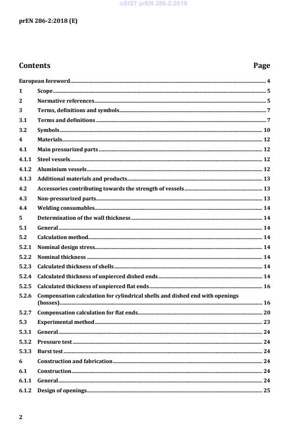
European foreword . 4
1 Scope . 5
2 Normative references . 5
3 Terms, definitions and symbols . 7
3.1 Terms and definitions . 7
3.2 Symbols . 10
4 Materials . 12
4.1 Main pressurized parts . 12
4.1.1 Steel vessels. 12
4.1.2 Aluminium vessels . 12
4.1.3 Additional materials and products . 13
4.2 Accessories contributing towards the strength of vessels . 13
4.3 Non-pressurized parts . 13
4.4 Welding consumables . 14
5 Determination of the wall thickness . 14
5.1 General . 14
5.2 Calculation method . 14
5.2.1 Nominal design stress. 14
5.2.2 Nominal thickness . 14
5.2.3 Calculated thickness of shells . 14
5.2.4 Calculated thickness of unpierced dished ends . 14
5.2.5 Calculated thickness of unpierced flat ends . 16
5.2.6 Compensation calculation for cylindrical shells and dished end with openings
(bosses) . 16
5.2.7 Compensation calculation for flat ends . 20
5.3 Experimental method . 23
5.3.1 General . 24
5.3.2 Pressure test . 24
5.3.3 Burst test . 24
6 Construction and fabrication . 24
6.1 Construction . 24
6.1.1 General . 24
6.1.2 Design of openings . 25
oSIST prEN 286-2:2019
prEN 286-2:2018 (E)
6.1.3 Weld joint design . 25
6.1.4 Inspection openings . 26
6.1.5 Drainage openings . 30
6.1.6 Attachments . 30
6.2 Fabrication . 30
6.2.1 Forming of plates . 30
6.2.2 Tolerances on fit-up . 30
6.2.3 Heat treatment for aluminium alloy . 31
6.2.4 Welding . 31
7 Qualification of welders, welding operators and welding inspectors . 31
8 Qualification of welding procedures . 31
8.1 Welding procedure test . 31
8.2 Requirements . 31
8.2.1 Welded joints on steel . 31
8.2.2 Welded joints on aluminium . 32
9 Resistance to corrosion . 32
9.1 General . 32
9.2 Steel vessels . 32
9.3 Aluminium vessels . 32
10 Tests and certificates . 33
10.1 Tests to be carried out during manufacture . 33
10.1.1 General requirement . 33
10.1.2 Vessels designed by the calculation method . 33
10.1.3 Vessels designed by the experimental method. 38
10.2 Pressure test . 39
11 Marking . 39
12 Operating instructions . 40
Annex A (normative) KV requirements for plate and strip materials (steel) . 41
Annex B (normative) Pressure cycling operation . 43
Annex C (normative) Test of the protection against corrosion . 44
C.1 Test samples . 44
C.2 Grid test of paints . 44
C.3 Salt spray test . 44
Annex ZA (informative) Relationship between this European Standard and the essential
requirements of Directive 2014/29/EU aimed to be covered . 46
Bibliography . 47
oSIST prEN 286-2:2019
prEN 286-2:2018 (E)
European foreword
This document (prEN 286-2:2019) has been prepared by Technical Committee CEN/TC 54 “Unfired
pressure vessels”, the secretariat of which is held by BSI.
This document is currently submitted to the CEN Enquiry.
This document will supersede EN 286-2:1992.
This document has been prepared under a mandate given to CEN by the European Commission and the
European Free Trade Association, and supports essential requirements of the EU Directive
2014/29/EU.
For relationship with EU Regulation 2014/29/EU, see the informative Annex ZA, which is an integral
part of this document.
oSIST prEN 286-2:2019
prEN 286-2:2018 (E)
1 Scope
1.1 This document applies to the design and manufacture of simple unfired serially made pressure
vessels, herein after referred to as vessels, designed for air breaking equipment and auxiliary systems
for motor vehicles and their trailers, and which:
a) include fabrication by welding;
b) have a simple geometry enabling simple-to-use production procedures. This is achieved by either:
1) a cylindrical shell of circular cross section closed by outwardly dished and/or flat ends having
the same axis of revolution as the shell; or:
2) two dished ends having the same axis of revolution;
c) have branches not larger in diameter than 0,5 of the diameter of the cylinder to which they are
welded.
1.2 It applies only to vessels intended to contain compressed air, and which operate within the
following constraints:
a) subjected to an internal pressure greater than 0,5 bar;
b) the parts and assemblies contributing to the strength of the vessel under pressure to be made
either of non-alloy quality steel or of non-alloy aluminium or non-age hardening aluminium alloys;
c) maximum working pressure 30 bar, the product of that pressure and the capacity of the vessel
(PS ∙ V) is greater than 50 bar litres and not exceeding 1 500 bar litres;
d) capacity not exceeding 150 litres;
e) minimum working temperature not lower than −50 °C and maximum working temperature not
higher than 100 °C.
It does not apply to vessels specifically designed for nuclear use, to vessels specifically intended for
installation in or the propulsion of ships and aircraft, or to fire extinguishers.
2 Normative references
The following documents are referred to in the text in such a way that some or all of their content
constitutes requirements of this document. For dated references, only the edition cited applies. For
undated references, the latest edition of the referenced document (including any amendments) applies.
EN 10028-1:2017, Flat products made of steels for pressure purposes - Part 1: General requirements
EN 10028-2:2017, Flat products made of steels for pressure purposes - Part 2: Non-alloy and alloy steels
with specified elevated temperature properties
EN 10207:2017, Steels for simple pressure vessels - Technical delivery requirements for plates, strips and
bars
EN 10216-1:2013, Seamless steel tubes for pressure purposes - Technical delivery conditions - Part 1: Non-
alloy steel tubes with specified room temperature properties
oSIST prEN 286-2:2019
prEN 286-2:2018 (E)
EN 10217-1:2019, Welded steel tubes for pressure purposes - Technical delivery conditions - Part 1:
Electric welded and submerged arc welded non-alloy steel tubes with specified room temperature
properties
EN 10217-2:2019, Welded steel tubes for pressure purposes - Technical delivery conditions - Part 2:
Electric welded non-alloy and alloy steel tubes with specified elevated temperature properties
EN 10222-2:2017, Steel forgings for pressure purposes - Part 2: Ferritic and martensitic steels with
specified elevated temperatures properties
EN ISO 148-1:2016, Metallic materials - Charpy pendulum impact test - Part 1: Test method (ISO 148-
1:2016)
EN ISO 2409:1994, Paints and varnishes — Cross-cut test (ISO 2409:1992)
EN ISO 4136:2012, Destructive tests on welds in metallic materials - Transverse tensile test (ISO
4136:2012)
EN ISO 5173:2010, Destructive tests on welds in metallic materials — Bend tests
EN ISO 5817:2014, Welding - Fusion-welded joints in steel, nickel, titanium and their alloys (beam welding
excluded) - Quality levels for imperfections (ISO 5817:2014)
EN ISO 6520-1:2007, Welding and allied processes - Classification of geometric imperfections in metallic
materials - Part 1: Fusion welding (ISO 6520-1:2007)
EN ISO 6892-1:2016, Metallic materials - Tensile testing - Part 1: Method of test at room temperature (ISO
6892-1:2016)
EN ISO 9227:2017, Corrosion tests in artificial atmospheres - Salt spray tests (ISO 9227:2017)
EN ISO 9606-1:2017, Qualification testing of welders - Fusion welding - Part 1: Steels (ISO 9606-1:2012
including Cor 1:2012 and Cor 2:2013)
EN ISO 9606-2:2004, Qualification test of welders - Fusion welding - Part 2: Aluminium and aluminium
alloys (ISO 9606-2:2004)
EN ISO 10042:2018, Welding - Arc-welded joints in aluminium and its alloys - Quality levels for
imperfections (ISO 10042:2018)
EN ISO 14341:2011, Welding consumables - Wire electrodes and weld deposits for gas shielded metal arc
welding of non alloy and fine grain steels - Classification (ISO 14341:2010)
EN ISO 14732:2013, Welding personnel - Qualification testing of welding operators and weld setters for
mechanized and automatic welding of metallic materials (ISO 14732:2013)
EN ISO 15607:2003, Specification and qualification of welding procedures for metallic materials - General
rules (ISO 15607:2003)
EN ISO 15609-1:2004, Specification and qualification of welding procedures for metallic materials -
Welding procedure specification - Part 1: Arc welding (ISO 15609-1:2004)
As impacted by EN ISO 5173:2010/A1:2011.
oSIST prEN 286-2:2019
prEN 286-2:2018 (E)
EN ISO 15614-1:2017, Specification and qualification of welding procedures for metallic materials -
Welding procedure test - Part 1: Arc and gas welding of steels and arc welding of nickel and nickel alloys
(ISO 15614-1:2017)
EN ISO 15614-2:2005, Specification and qualification of welding procedures for metallic materials -
Welding procedure test - Part 2: Arc welding of aluminium and its alloys (ISO 15614-2:2005)
EN ISO 17636-1:2013, Non-destructive testing of welds - Radiographic testing - Part 1: X- and gamma-ray
techniques with film (ISO 17636-1:2013)
EN ISO 17636-2:2013, Non-destructive testing of welds - Radiographic testing - Part 2: X- and gamma-ray
techniques with digital detectors (ISO 17636-2:2013)
EN ISO 18273:2015, Welding consumables - Wire electrodes, wires and rods for welding of aluminium and
aluminium alloys - Classification (ISO 18273:2015)
ISO 209:2007, Aluminium and aluminium alloys — Chemical composition
ISO 2107:2007, Aluminium and aluminium alloys — Wrought products — Temper designations
ISO 6361-2:2014, Wrought aluminium and aluminium alloys — Sheets, strips and plates — Part 2:
Mechanical properties
3 Terms, definitions and symbols
3.1 Terms and definitions
For the purposes of this document, the following terms and definitions apply.
ISO and IEC maintain terminological databases for use in standardization at the following addresses:
— ISO Online browsing platform: available at https://www.iso.org/obp
— IEC Electropedia: available at http://www.electropedia.org/
3.1.1
type examination
procedure by which a notified body ascertains and certifies that a specimen of a vessel satisfies the
requirements of this document
3.1.2
conformity assessment
procedure adopted at the choice of the manufacturer to check and certify that the manufactured vessels
comply with this document
3.1.3
declaration of conformity
confirmation of the manufacturer that the vessels are in conformity with this document
3.1.4
controlled product test
procedure carried out by a notified body during manufacture to ensure that the manufacturer duly
fulfils the requirements of this document
oSIST prEN 286-2:2019
prEN 286-2:2018 (E)
3.1.5
design and manufacturing documents
prepared by the manufacturer to describe the construction, materials and fabrication including the
certificates
3.1.6
manufacturer’s inspector
person(s) employed by the manufacturer, but sufficiently independent from the production personnel,
qualified and responsible for inspections, examinations and tests to be carried out on vessels by him or
under his responsibility by competent staff
3.1.7
qualification of the inspector
qualification means technical competency on the different inspections, examinations and tests to be
carried out under the manufacturer’s responsibility, as well as necessary experience
Note 1 to entry: It is the responsibility of the manufacturer to ascertain that the inspector is competent
3.1.8
automatic welding
welding in which all the welding parameters are automatically controlled, some of these parameters
may be adjusted to a limited amount (manually or automatically by mechanical or electronic devices)
during welding to maintain the specified welding conditions
3.1.9
non-automatic welding
all types of welding other than that defined in 3.1.8
3.1.10
type of vessel
vessels are of the same type if they simultaneously:
— have similar geometrical form (i.e. shell rings and ends or only ends, in both cases ends of the same
shape);
— have wall material and thickness within the limit of validity of the welding procedure test, including
those for bosses and inspection openings;
— have the same type of bosses and of inspection openings; numbers and positions may vary;
— have the same design temperature limitations
3.1.11
batch
consists at most of 3 000 vessels of the same type
3.1.12
series manufacture
more than one vessel of the same type manufactured during a given period by a continuous
manufacturing process in accordance with a common design and using the same manufacturing process
oSIST prEN 286-2:2019
prEN 286-2:2018 (E)
3.1.13
family
vessels form part of the same family if they differ only in diameter and/or in the length of their
cylindrical portions
3.1.14
subfamily
vessels of the same family with the same wall thicknesses, the same material, the same welding
procedure, the same construction of details; the vessels may vary in number and position of
attachments and bosses
3.1.15
maximum design temperature
temperature that is used in the design calculations, and which is never less than the maximum working
temperature
3.1.16
minimum design temperature
lowest temperature used in the selection of materials, and which is never greater than the minimum
working temperature
3.1.17
maximum working temperature
T
max
highest stabilized temperature which the wall of the vessel may attain under normal conditions of use
3.1.18
minimum working temperature
T
min
lowest stabilized temperature in the wall of the vessel under normal conditions use
3.1.19
maximum working pressure
PS
maximum gauge pressure which may be exerted under normal conditions of use
3.1.20
design pressure
P
pressure chosen by the manufacturer and used to determine the thickness of the pressurized parts
3.1.21
inspection slip
document by which the producer certifies that the products delivered meet the requirements of the
order and in which they set out the results of the routine in-plant inspection test, in particular chemical
composition and mechanical properties, performed on products made by the same production process
as the supply, but not necessarily on products delivered
Note 1 to entry: This corresponds to test report “2.2” defined in EN 10204.
oSIST prEN 286-2:2019
prEN 286-2:2018 (E)
3.2 Symbols
For the purpose of this document, the following symbols apply:
A, A Elongation after rupture %
80mm
A , A See 5.2.7. 2
c R mm
A Cross sectional area effective as compensation 2
f mm
A Cross sectional area effective as compensation of the boss 2
fb mm
A Cross-sectional area effective as compensation of the shell 2
fs mm
A Area of pressurized zone 2
p mm
c Absolute value of the negative tolerance taken from the material standard mm
or as stated in the drawing plus the absolute value of the reduction of wall
thickness by the forming process
c As before for a branch or boss mm
b
C Calculation coefficient for unpierced flat ends —
d Diameter of hole mm
d Internal diameter of a boss mm
ib
d Outside diameter of a boss mm
ob
D Inside diameter of an unpierced flat end mm
D Outside diameter of the crown section of a torispherical end measured mm
c
to the tangent between crown and knuckle
D Outside diameter of the shell/ends mm
o
e Nominal wall thickness mm
e Actual wall thickness mm
a
e Actual wall thickness of the shell before the pressure test mm
act
e Actual wall thickness of the end mm
ah
e Actual wall thickness of the shell mm
as
e Calculated thickness mm
c
e Calculated wall thickness of a branch or a fictitious branch with the same mm
cb
internal diameter as the boss
e Calculated wall thickness of the dished end mm
ch
e Calculated wall thickness of the shell mm
cs
e Nominal wall thickness of the dished end mm
h
e e — corresponding nominal wall thickness as stated in the design mm
n act
drawing
e Wall thickness of boss contributing to reinforcement mm
rb
oSIST prEN 286-2:2019
prEN 286-2:2018 (E)
e Wall thickness of shell contributing to reinforcement mm
rs
e Wall thickness of the shell mm
s
f Nominal design stress 2
N/mm
g Throat thickness of a weld mm
h Height of a dished end mm
h , h , h , h See 5.2.6.1 and Figure 3. mm
b be be1 be2
K Calculation coefficient which depends on the welding process —
c
KCV Failure energy (impact test) 2
J/cm
KV Failure energy (impact test) J
l Length between adjacent bosses mm
b
l Length of boss contributing to reinforcement mm
rb
l Length of shell contributing to reinforcement mm
rs
L See 5.2.7. mm
m See C.3. —
N See 6.1.3.1 and C.3. —
2)
P bar
Design pressure (which shall not be less than PS)
P 1) bar
h Test pressure
PS 1) bar
Maximum working pressure
r Inside knuckle radius for torispherical ends
R Inside radius for shells and ends mm
R Minimum yield strength specified in the material standard 2
e N/mm
R Yield strength of the shell material as determined in the tensile test 2
e act N/mm
R Minimum yield strength at maximum working temperature specified in the 2
eT N/mm
material standard
R Minimum tensile strength specified in the material standard or guaranteed 2
m N/mm
in the inspection slip by the material manufacturer
R Tensile strength of the shell material as determined in the tensile test 2
m act N/mm
T Temperature °C
T Maximum working temperature °C
max
T Minimum working temperature °C
min
T′ Minimum ambient temperature °C
min
2)
All pressures are gauge pressures.
oSIST prEN 286-2:2019
prEN 286-2:2018 (E)
u Circumferential length at cross section i after the pressure test mm
i
u Circumferential length at cross section i before the pressure test mm
io
V Capacity of the vessel litre
4 Materials
4.1 Main pressurized parts
4.1.1 Steel vessels
The following materials shall be used:
a) Plate, strip and bar according to EN 10207:2017 (grades P235S, P265S, and P275SL), or to
EN 10028-1:2017 and EN 10028-2:2017 (grades P235GH and P265GH).
For these grades of steel the compliance to the essential safety requirements according to the
average failure energy KV of steels at the minimum working temperature may be checked by the
use of Annex A.
b) Tubes according to EN 10216-1:2013 and EN 10217-1:2019 (grades P235 TR2 and P 265 TR2) and
EN 10217-2:2019 (grades P 195 GH, P 235 GH and P 265 GH).
c) Forgings according to EN 10222-2:2017.
For a), b) and c), the materials shall be accompanied by an inspection slip verifying the suitability of the
material, including all the criteria required. In the case of materials according to b) and c) the inspection
slip shall contain specific references to the requirements.
4.1.2 Aluminium vessels
The following materials shall be used (see Table 1).
Table 1 — Aluminium materials
Design
Temperature
c
temperature
°C
°C
International
Maximum
20 50 100 20 50 100
ISO Temper
registration
temperature
a b
designation designation
Minimum proof
a
°C
Maximum
record
d
stress design stress
R f
p0,2
2 N/mm
N/mm
Al99,8 (A) 1080 A 0 100 22 20 18 13 12 11
Al99,7 1070 A 0 100 25 23 20 15 14 13
Al99,5 1050 A 0 100 30 29 27 18 17 16
AlMg1 (B) 5005 A 0 100 35 35 35 21 21 21
AlMg2 5251 0 100 60 60 60 36 36 36
AlMg2Mn0,8 5049 0 100 80 80 70 48 48 42
oSIST prEN 286-2:2019
prEN 286-2:2018 (E)
Design
Temperature
c
temperature
°C
°C
International
Maximum
20 50 100 20 50 100
ISO Temper
registration
temperature
a b
designation designation
Minimum proof
a
°C
Maximum
record
d
stress design stress
R f
p0,2
2 N/mm
N/mm
AlMg2,5 5052 0 100 60 60 57 36 36 34
AlMg3 5754 0 100 80 80 70 48 48 42
AlMg3Mn 5454 0 100 90 90 90 54 54 54
AlMg3,5 (A) 5154 A 0 100 90 90 90 54 54 54
AlMg 4 5086 0 65 100 100 e 60 60 e
90 54
AlMg4,5Mn0,7 5083 0 65 125 125 e 75 75 e
120 72
AlMn1 3103 0 100 35 35 30 21 21 18
AlMn0,5Mg0,5 3105 0 100 40 40 37 24 24 22
a
ISO designation and international registration record, see ISO 209:2007.
b
Temper designation, see ISO 2107:2007.
c
For intermediate design temperatures, linear interpolation may be used.
d
R for aluminium, R for aluminium alloys.
p1,0 p0,2
e
For interpolation purposes only, temperature limit 65 °C.
For other products (e.g. bars and rods), materials according to ISO 6362-2 should be used so far as they
fulfil the requirements.
4.1.3 Additional materials and products
Any materials not included in 4.1.1 and 4.1.2, which are manufactured according to a recognized
National or International Standard for quality steels, aluminium or aluminium alloy and which conform
to the essential safety requirements will be acceptable subject to approval by a notified body in order to
have type examination of the vessel and include the suitability of the material. Such materials shall be
accompanied by a notified body certificate verifying the suitability of the materials.
4.2 Accessories contributing towards the strength of vessels
These accessories (pipes/tubes, bosses etc.) shall be manufactured from circular profiles or pipes/tubes
made of steel grades, aluminium or aluminium alloys, which is/are compatible with the materials used
for the manufacture of pressurized parts. They shall have an elongation after rupture, A, on test pieces
taken in the length of at least 14 % (see EN ISO 6892-1:2016).
4.3 Non-pressurized parts
All unpressurized parts of welded vessels shall be of materials that are compatible with that of the
components to which they are welded.
oSIST prEN 286-2:2019
prEN 286-2:2018 (E)
To this end, for steel vessels, supports and accessories fitted by welding on, the shells and ends shall be
made of non-alloy steel which meets the following requirements:
C ≤ 0,25 %, S ≤ 0,05 %, P ≤ 0,05 % and
R ≤ 580 N/mm
m max
Aluminium and aluminium alloys shall be as given in 4.1.2.
4.4 Welding consumables
The welding consumables used to manufacture the welds on or of the vessel shall be suitable and
compatible with the materials to be welded.
The shall correspond to EN ISO 14341:2011 or EN ISO 18273:2015.
5 Determination of the wall thickness
5.1 General
The manufacturer may determine the wall thickness of pressurized parts by either the calculation
method given in 5.2 or by the experimental method given in 5.2.
The actual wall thickness of the cylindrical section and ends shall be not less than 2 mm in the case of
steel vessels and not less than 3 mm in the case of aluminium or aluminium alloy vessels. That means:
the minimum nominal wall thickness is 2 mm + c for pressure vessels made of steel and 3 mm + c for
pressure vessels made of aluminium.
5.2 Calculation method
5.2.1 Nominal design stress
The nominal design stress, f, shall not exceed the lower value of 0,6 R or 0,3 R , where R and R
eT m eT m
are the values specified in the material standards.
5.2.2 Nominal thickness
The nominal thickness of shells and ends, e, shall be equal to or greater than
e ≥ e + c (1)
c
5.2.3 Calculated thickness of shells
P D
o
eK=
(2a)
cs c
20 fP+
K = 1,0 or 1,15, depending on the welding process. The type of testing adopted, see 10.1.2.2, Tables 6
c
to 9, depends on the value of K and P.
c
5.2.4 Calculated thickness of unpierced dished ends
5.2.4.1 Limitations
Dished ends shall fulfil the following limitations:
a) hemispherical ends: 0,002 D ≤ e ≤ 0,16 D ;
o ch o
oSIST prEN 286-2:2019
prEN 286-2:2018 (E)
b) ellipsoidal ends: 0,002 D ≤ e ≤ 0,08 D ;
o ch o
h = h ≥ 0,18 D ;
e o
c) torispherical ends: 0,002 D ≤ e ≤ 0,08 D ;
o ch o
r ≥ 0,06 D ;
o
r ≥ 3 e
ch
R ≤ D .
o
The values of the limitation conditions for R are nominal ones; tolerances up to 4 % are allowed.
It should be noted that the two relationships in b) or the four relationships in c) should be fulfilled
simultaneously.
In no case, except in Figure 6, shall the thickness of the cylindrical or straight flange of a dished end be
less than the thickness of a seamless unpierced cylindrical shell of the same diameter and material for
the same design pressure and temperature.
5.2.4.2 Calculations for hemispherical ends
The thickness of hemispherical ends shall be determined using equation:
PD
o
e = K
(2b)
ch c
40 fP+
K see 5.2.3.
c
5.2.4.3 Calculations for ellipsoidal and torispherical ends
This calculation may be performed by the following procedure.
a) Calculate P/(10f) from the design pressure P and the design stress f.
Calculate h /D where, for torispherical ends, h is the smallest of the three values
e o e
D / 4 Re+ D re+ / 2
( ) or or h, where
( )
o ch o ch
h=R+ e − Rr− − D / 2−−e r
( ) ( )
ch o ch
b) Enter Figure 2 with this value, read up to the appropriate h /D line for the proposed end shape
e o
and then across to the e /D axis for the corresponding e /D value.
ch o ch o
Interpolation between h /D curves is permissible or, alternatively, values may be read from the
e o
next highest h /D curve.
e o
NOTE The values which correspond to Figure 2 are given in Table 2.
c) Multiply this e /D value by D to obtain the end thickness e .
ch o o ch
The thickness of the spherical portion of a torispherical end may be determined as for a hemispherical
end of spherical radius R with the area of diameter D − 2z,
c
oSIST prEN 286-2:2019
prEN 286-2:2018 (E)
where
z 0,5 R× torisperical thickness
Figure 2 may be used with the values of h and D based an internal dimensions, provided
e o
h /D < 0,27; beyond this value external dimensions are to be used.
e o
5.2.5 Calculated thickness of unpierced flat ends
The minimum thickness of an unstayed flat end without opening is given by the following equation:
P
e= CD
(3)
10 f
where
C = 0,5.
5.2.6 Compensation calculation for cylindrical shells and dished end with openings (bosses)
5.2.6.1 Compensation calculation is not required if
— the internal diameter of the opening is
d≤−0,14 D ee
(4a)
( )
o aa
or if
— the internal diameter of the opening is:
e − ec−
ac
d≤ 22 D −−ee e + c
( ) ( ) (4b)
o cb b
e
c
or if
— the following conditions for the dimensions of the boss and the opening are fulfilled (see Figure 3)
d
h ⋅ e ≥ ⋅ e (4c)
be rb c
d ≤ 40 mm
b
where h is the smaller of the two values of h or 6 e (in case of Figures 3a and 3b) respectively or the
be b c
smaller of the two values of h or 10 e under the restrictions of h ≤ 6 e and h ≤ 6 e (in case of
b c be1 c be2 c
Figure 3c).
5.2.6.2 If conditions under 5.2.6.1 are not fulfilled, the design method specified as follows shall
apply to cylindrical shells and dished ends having circular openings, where the assumptions and
conditions specified in 5.2.6.3 and 5.2.6.4 are satisfied.
=
oSIST prEN 286-2:2019
prEN 286-2:2018 (E)
5.2.6.3 The distance between two openings, measured from the outside, shall not be less than 10 e.
3)
If the distance between openings is greater than or equal to 2 l , where
rs
l 2Re+ e (5)
( )
rs rs rs
then the necessary reinforcement shall be calculated according to 5.2.6.6, case A or C.
If the distance between openings is smaller than 2 l , the necessary reinforcement shall be calculated
m
according to 5.2.6.6, case B or D.
5.2.6.4 The reinforcement of the main body or the dished end can be obtained alternatively by:
— set-in welded bosses including projection welding and
— set-on welded bosses friction welding
— increased wall thickness.
Figure 1a — Hemispherical Figure 1b — Ellipsoidal end Figure 1c — Torispherical end
end
Figure 1 — Types of ends
3)
Also see Formula (1) in 6.1.3.5.
=
oSIST prEN 286-2:2019
prEN 286-2:2018 (E)
Key
a values of h /D
e 0
NOTE The scale is logarithmic
Figure 2 — Design curves for dished ends
oSIST prEN 286-2:2019
prEN 286-2:2018 (E)
Table 2 — Values of (e /D ) ⋅ 10 for unpierced dished ends in terms of h /D and P/(10f)
ch o e o
P/(10f)
h
e
D
o 0,001 0,002 Greater
0,001 0,004 0,006 0,010 0,015 0,025 0,050
5 5 values
0,15 2,13 2,70 3,73 5,22 7,20 10,9 15,4 24,0 44,5 880 × P/(10f)
0,16 (1,95) 2,50 3,50 4,90 6,70 10,2 14,3 22,2 41,5 810 × P/(10f)
0,17 (1,80) 2,30 3,24 4,58 6,30 9,6 13,5 21,0 39,2 770 × P/(10f)
0,18 (1,65) 2,11 2,99 4,23 5,80 8,8 12,6 19,7 37,0 730 × P/(10f)
0,19 (1,95) 2,77 3,95 5,43 8,3 11,8 18,5 35,0 695 × P/(10f)
0,20 (1,80) 2,55 3,64 5,00 7,7 11,0 17,3 33,0 650 × P/(10f)
0,21 (1,65) 2,39 3,42 4,75 7,3 10,4 16,2 620 × P/(10f)
0,22 (1,52) 2,22 3,20 4,45 6,84 9,7 15,4 585 × P/(10f)
0,23 (1,40) 2,08 2,95 4,12 6,30 9,1 14,5 555 × P/(10f)
0,24 (1,92) 2,76 3,83 5,90 8,5 13,6 530 × P/(10f)
0,25 (1,75) 2,58 3,56 5,50 7,8 500 × P/(10f)
0,26 (1,64) 2,40 3,34 5,15 7,35 475 × P/(10f)
0,27 (1,52) 2,25 3,12 4,80 6,80 445 × P/(10f)
0,28 (1,41) 2,12 2,93 4,50 6,45 425 × P/(10f)
0,29 (2,00) 2,73 4,20 405 × P/(10f)
0,30 (1,86) 2,54 3,95 385 × P/(10f)
0,31 (1,71) 2,41 3,80 370 × P/(10f)
0,32 (1,61) 2,30 3,65 358 × P/(10f)
0,33 (1,52) 2,20 3,50 345 × P/(10f)
0,34 (1,45) 2,10 335 × P/(10f)
0,35 325 × P/(10f)
0,36 319 × P/(10f)
0,38 307 × P/(10f)
0,40 295 × P/(10f)
NOTE 1 This table is not valid for values of (e /D ) ⋅ 10 < 2,00.
ch o
NOTE 2 Intermediate values can be obtained by logarithmic interpolation.
NOTE 3 Values in parentheses are provided for purposes of interpolation.
5.2.6.5 The reinforcement area of the main body with openings cannot be calculated directly but
shall be assumed in the first instance. That assumption may be verified by means of the method laid
down in the following clause. The applied method is derived from Formula (2a) for cylindrical shells
and from Formula (2b) for spherical shells and spherical sections of dished ends respectively and leads
to relationships between a pressure loaded area A and a stress loaded cross-sectional area A . Under
p f
certain circumstances the calculation may need to be repeated using a corrected assumption of the
reinforcement area.
5.2.6.6 The calculation of reinforcement is to be performed as shown in Table 3 in combination
with Figures 4a to 4d. For ends the calculation of A , A and A is evident from Figures 4a to 4d. For
p fs fb
oSIST prEN 286-2:2019
prEN 286-2:2018 (E)
cylindrical shells the Figures 4a to 4d can be used for calculation of the effective area (A and A ) but it
fs fb
should be noted that
d
A R l+ (6)
p rs
if the distance between holes ≥ 2 l
rs
and
d d
A R l++ (7)
pb
2 2
if the distance between holes < 2 l but ≥ 10 e.
rs
5.2.7 Compensation calculation for flat ends
Flat ends that have an opening of D/2 or less shall be provided with reinforcement by the following
equation:
A ≥ A (8)
R c
The area A is obtained by multiplying the difference between the adopted plate thickness and the plate
R
thickness (calculated in accordance with 5.2.5) × Length L.
The area A is given by d/2 × calculated thickness e in accordance with 5.2.5.
c
L is given by the greater of the 3 values of 2,5 e or (e + 75 mm) or d/2.
NOTE 1 This method of compensation is widely used and experience has proved it to be satisfactory for a wide
range of applications. However, because of the simplified nature of the calculations, its use is limited.
NOTE 2 This method of compensation takes account of the cross-sectional area of locally disposed material.
Table 3 — Calculation of reinforcement (see also Figures 4a to 4d)
Reinforcement by set-in or set-on bosses Reinforcement by increased wall thickness
Distance Case A (Figure 4a) Case C (Figure 4
...