

prEN 16793
(Main)Guide for the selection, application and use of flame arresters
- Abstract
This document is aimed primarily at persons who are responsible for the safe design and operation of installations and equipment using flammable liquids, vapours or gases.
This document applies to both industrial and mining applications.
This document describes possible risks and gives proposals for the protection against these risks by the use of flame arresters.
This document gives some guidance for the selection and installation of flame arresters according to EN ISO/IEC 80079-49 for different common scenarios and it gives best practice for the installation and maintenance of these flame arresters.
This document is applicable to pressures ranging from 80 kPa to 160 kPa and temperatures ranging from −20 °C to +200 °C.
- Status
- Not Published
- Publication Date
- 15-Sep-2027
- Technical Committee
- CEN/TC 305 - Potentially explosive atmospheres - Explosion prevention and protection
- Drafting Committee
- CEN/TC 305/WG 6 - Flame arresters

prEN 16793 is a CEN draft European Standard for the selection, application and use of flame arresters. It is aimed at people responsible for the safe design and operation of installations and equipment using flammable liquids, vapours or gases, in both industrial and mining applications. The document explains the risks, the main flame arrester types, and the practical choices that matter for selection, installation, operation and maintenance.
What does prEN 16793 specify?
prEN 16793 gives guidance for choosing and using flame arresters in common operating scenarios, with a focus on avoiding flame transmission in systems that handle flammable media. It also sets the operating range covered by the guide: pressures from 80 kPa to 160 kPa and temperatures from -20 °C to +200 °C.
The document is organized into general explosion-protection background, flame arrester types and selection, application limits, installation and maintenance, a commissioning checklist, and two informative annexes.
| Annex | What it covers |
|---|---|
| Annex A | Example of a safety concept |
| Annex B | Guidelines for arranging flame arresters at pipe branches |
What are the key requirements of prEN 16793?
prEN 16793 is mainly a practical selection and installation guide, but it still sets out clear conditions that users need to check before using a flame arrester. In practice, the reader has to match the device type, the gas or vapour, the piping layout, and the operating conditions to the intended duty.
Explosion protection and isolation
Clause 5 says that if ignition cannot be prevented, the explosion effect should be reduced by explosion-resistant design, explosion relief, explosion suppression, or prevention of flame and explosion propagation. It also explains that explosion isolation can be achieved with flameproof closed isolation valves or flame arresters.
In practice, this means a flame arrester is one part of a wider protection concept, not a stand-alone solution.
Flame arrester type and operating principle
Clause 6 describes the main flame arrester principles: static flame arresters that quench the flame, liquid-product or hydraulic barriers, and dynamic devices such as high-velocity pressure relief valves. Clause 6.3 separates end-of-line, in-line, pre-volume, and burning-rated arrangements.
This matters because the right device depends on whether the hazard is outside the opening, inside a pipeline, inside a containment, or linked to stabilized burning at the element.
Selection must follow the actual installation
Clause 6.4 requires the user to assess what is to be protected, where ignition sources may be, where an explosive atmosphere may occur, which type of explosive atmosphere can form, the operating pressure and temperature, and the geometry of the pipework or vessel.
The same clause links selection to the installation position. End-of-line units are used for openings to atmosphere, in-line units for propagation in pipework, and pre-volume units where an internal explosion in a containment must not pass into other connected equipment.
Explosion group and MESG
Clause 6.4 uses Explosion Groups and the Maximum Experimental Safe Gap (MESG) to classify gas and vapour mixtures. The document states that the application is limited to mixtures with an MESG equal to or greater than that tested for the arrester.
For the user, this means the mixture itself must be checked, not just the pipe size or connection type. Clause 6.4 also excludes self-decomposing, chemically unstable, oxygen-enriched, and certain oxidizing mixtures from standard approval, so these cases need special testing and marking.
Application limits and marking
Clause 6.5 says the marking on the arrester includes the protected side, explosion group, maximum operating temperature, maximum operating pressure, type designation, and burn classification where relevant. It also requires the warning that flame arresters have installation and application limits.
This is important in buying and inspection: the nameplate and warning text must match the real service conditions, not just the general product family.
Installation limits are part of safe use
Clause 6.6 sets limits on installation orientation, combinations with machines, plugging, permitted pipe lengths, and nominal pipe sizes. For in-line deflagration flame arresters, the permitted pipe length on the unprotected side is limited by the tested L/D ratio, and the device should be installed as close as possible to the ignition source.
In practice, that means the piping layout can decide whether a flame arrester is suitable at all. The document also requires care with branch connections, valve positions, and avoidance of diameter reductions unless the manufacturer allows them.
Burning conditions and temperature sensing
Clause 6.3.6 and Clause 7.2.3 distinguish short time burning and endurance burning. Where stabilized burning can occur, the document calls for temperature sensors and emergency actions such as shutdown, inerting, enriching above the upper explosion limit, or diluting below the lower explosion limit.
This matters on vents, vapour lines, and other duties with sustained flow, because the main risk is no longer only flame transmission but continued burning at the element.
Maintenance, inspection and commissioning
Clause 8 requires trained personnel, correct installation, no unauthorized modification, and use of approved spare parts. It also highlights blockage, corrosion, mechanical damage, and inspection for signs of flame events.
Clause 9 gives an example commissioning checklist covering delivery, documentation, checks before installation, and checks before commissioning. In practice, this makes the handover step a formal safety check, not just a mechanical installation.
What terms does prEN 16793 define?
- Flame arrester - A device fitted to an enclosure opening or connecting pipework that lets flow pass but prevents flame transmission.
- End-of-line flame arrester - A flame arrester with one pipe connection only, used at openings to atmosphere or at tank vents.
- In-line flame arrester - A flame arrester with two pipe connections, one on each side, used in pipelines.
- Deflagration - An explosion that propagates at subsonic velocity.
- Detonation - An explosion that propagates at supersonic velocity and is characterized by a shock wave.
- Stable detonation - A detonation that progresses through a confined system without significant variation of velocity and pressure characteristics.
- Stabilized burning - Steady burning at or close to the flame arrester element, either for short time or for unlimited time.
- Maximum Experimental Safe Gap (MESG) - The safety classification value used to classify gas and vapour mixtures into explosion groups.
Who uses prEN 16793?
prEN 16793 is aimed at people who are responsible for the safe design and operation of plant using flammable liquids, vapours, or gases. That includes process engineers, safety engineers, maintenance teams, plant operators, tank and pipeline designers, and people selecting protective systems for industrial or mining installations.
The introduction also makes clear that it supports equipment selection, installation, maintenance, repair, and explosion-risk documentation. Buyers and quality managers use it to check whether a proposed flame arrester matches the intended service, operating limits, and installation layout.
What changed in prEN 16793 from the previous edition?
prEN 16793 supersedes CEN/TR 16793:2016. The European foreword states these main changes:
- change from Technical Report to European Standard
- change of references from EN ISO 16852 to EN ISO/IEC 80079-49
- shortening of Clause 4
- clarifications throughout the document
Which standards are used with prEN 16793?
prEN 16793 is built around EN ISO/IEC 80079-49:2024, which provides the performance requirements, test methods, and limits for flame arresters. The document also uses EN ISO/IEC 80079-20-1 for MESG determination.
Other standards named in the text add context or supporting guidance:
- EN 60079-32 series - referenced for potential equalization across flame arrester connections
- EN ISO 28300:2008 - referenced for inerted tanks and venting of atmospheric and low-pressure storage tanks
- EN 1127-1 - referenced in Annex A for the basic zone concept used in the safety example
What does the prEN 16793 document contain?
The document contains a simplified figure showing flame acceleration in a straight pipe and a set of tables that link flame arrester type, explosion group, burn class, and installation limits to the intended use. It also includes a commissioning checklist in Clause 9 that can be used as a practical handover record.
Clause 6 gives the device logic for end-of-line, in-line, pre-volume, liquid seal, hydraulic, and dynamic arrangements, along with rules for selection, marking, and installation. Clause 7 applies those rules to tanks, vessels, pipework, vapour venting, vapour recovery, and endurance-burning cases.
Annex A gives an example safety concept based on hazardous-area zones and independent protection measures. Annex B gives installation guidance for flame arresters at pipe branches, especially for detonation duties.
Relations
- Effective Date
- 28-Jan-2026
- Effective Date
- 28-Jan-2026
- Effective Date
- 28-Jan-2026
- Effective Date
- 09-Jun-2024
Get Certified
Connect with accredited certification bodies for this standard

CIS Institut d.o.o.
Personal Protective Equipment (PPE) certification body. Notified Body NB-2890 for EU Regulation 2016/425 PPE.
Institut za varilstvo d.o.o. (Welding Institute)
Slovenia's leading welding institute since 1952. ISO 3834, EN 1090, pressure equipment certification, NDT personnel, welder qualification. Only IIW Au

Kiwa BDA Testing
Building and construction product certification.
Sponsored listings
Frequently Asked Questions
prEN 16793 is a draft published by the European Committee for Standardization (CEN). Its full title is "Guide for the selection, application and use of flame arresters". This standard covers: This document is aimed primarily at persons who are responsible for the safe design and operation of installations and equipment using flammable liquids, vapours or gases. This document applies to both industrial and mining applications. This document describes possible risks and gives proposals for the protection against these risks by the use of flame arresters. This document gives some guidance for the selection and installation of flame arresters according to EN ISO/IEC 80079-49 for different common scenarios and it gives best practice for the installation and maintenance of these flame arresters. This document is applicable to pressures ranging from 80 kPa to 160 kPa and temperatures ranging from −20 °C to +200 °C.
This document is aimed primarily at persons who are responsible for the safe design and operation of installations and equipment using flammable liquids, vapours or gases. This document applies to both industrial and mining applications. This document describes possible risks and gives proposals for the protection against these risks by the use of flame arresters. This document gives some guidance for the selection and installation of flame arresters according to EN ISO/IEC 80079-49 for different common scenarios and it gives best practice for the installation and maintenance of these flame arresters. This document is applicable to pressures ranging from 80 kPa to 160 kPa and temperatures ranging from −20 °C to +200 °C.
prEN 16793 is classified under the following ICS (International Classification for Standards) categories: 13.220.99 - Other standards related to protection against fire; 23.060.40 - Pressure regulators. The ICS classification helps identify the subject area and facilitates finding related standards.
prEN 16793 has the following relationships with other standards: It is inter standard links to EN ISO 3834-3:2021, EN ISO 3834-4:2021, EN ISO 3834-2:2021, CEN/TR 16793:2016. Understanding these relationships helps ensure you are using the most current and applicable version of the standard.
prEN 16793 is available in PDF format for immediate download after purchase. The document can be added to your cart and obtained through the secure checkout process. Digital delivery ensures instant access to the complete standard document.
Standards Content (Sample)
SLOVENSKI STANDARD
01-november-2026
Smernice za izbiro, namestitev in uporabo plamenskih zapor
Guide for the selection, application and use of flame arresters
Richtlinie für die Auswahl, die Anwendung und den Einsatz von
Flammendurchschlagssicherungen
Guide pour la sélection, l'application et l'utilisation des arrête-flammes
Ta slovenski standard je istoveten z: prEN 16793
ICS:
13.220.99 Drugi standardi v zvezi z Other standards related to
varstvom pred požarom protection against fire
23.060.40 Tlačni regulatorji Pressure regulators
2003-01.Slovenski inštitut za standardizacijo. Razmnoževanje celote ali delov tega standarda ni dovoljeno.
DRAFT
EUROPEAN STANDARD
NORME EUROPÉENNE
EUROPÄISCHE NORM
November 2026
ICS 23.060.40; 13.220.99 Will supersede CEN/TR 16793:2016
English Version
Guide for the selection, application and use of flame
arresters
Guide pour la sélection, l'application et l'utilisation des Richtlinie für die Auswahl, die Anwendung und den
arrête-flammes Einsatz von Flammendurchschlagssicherungen
This draft European Standard is submitted to CEN members for enquiry. It has been drawn up by the Technical Committee
CEN/TC 305.
If this draft becomes a European Standard, CEN members are bound to comply with the CEN/CENELEC Internal Regulations
which stipulate the conditions for giving this European Standard the status of a national standard without any alteration.
This draft European Standard was established by CEN in three official versions (English, French, German). A version in any other
language made by translation under the responsibility of a CEN member into its own language and notified to the CEN-CENELEC
Management Centre has the same status as the official versions.
CEN members are the national standards bodies of Austria, Belgium, Bulgaria, Croatia, Cyprus, Czech Republic, Denmark, Estonia,
Finland, France, Germany, Greece, Hungary, Iceland, Ireland, Italy, Latvia, Lithuania, Luxembourg, Malta, Netherlands, Norway,
Poland, Portugal, Republic of North Macedonia, Romania, Serbia, Slovakia, Slovenia, Spain, Sweden, Switzerland, Türkiye and
United Kingdom.
Recipients of this draft are invited to submit, with their comments, notification of any relevant patent rights of which they are
aware and to provide supporting documentation.
Warning : This document is not a European Standard. It is distributed for review and comments. It is subject to change without
notice and shall not be referred to as a European Standard.
EUROPEAN COMMITTEE FOR STANDARDIZATION
COMITÉ EUROPÉEN DE NORMALISATION
EUROPÄISCHES KOMITEE FÜR NORMUNG
CEN-CENELEC Management Centre: Rue de la Science 23, B-1040 Brussels
© 2026 CEN All rights of exploitation in any form and by any means reserved Ref. No. prEN 16793:2026 E
worldwide for CEN national Members.
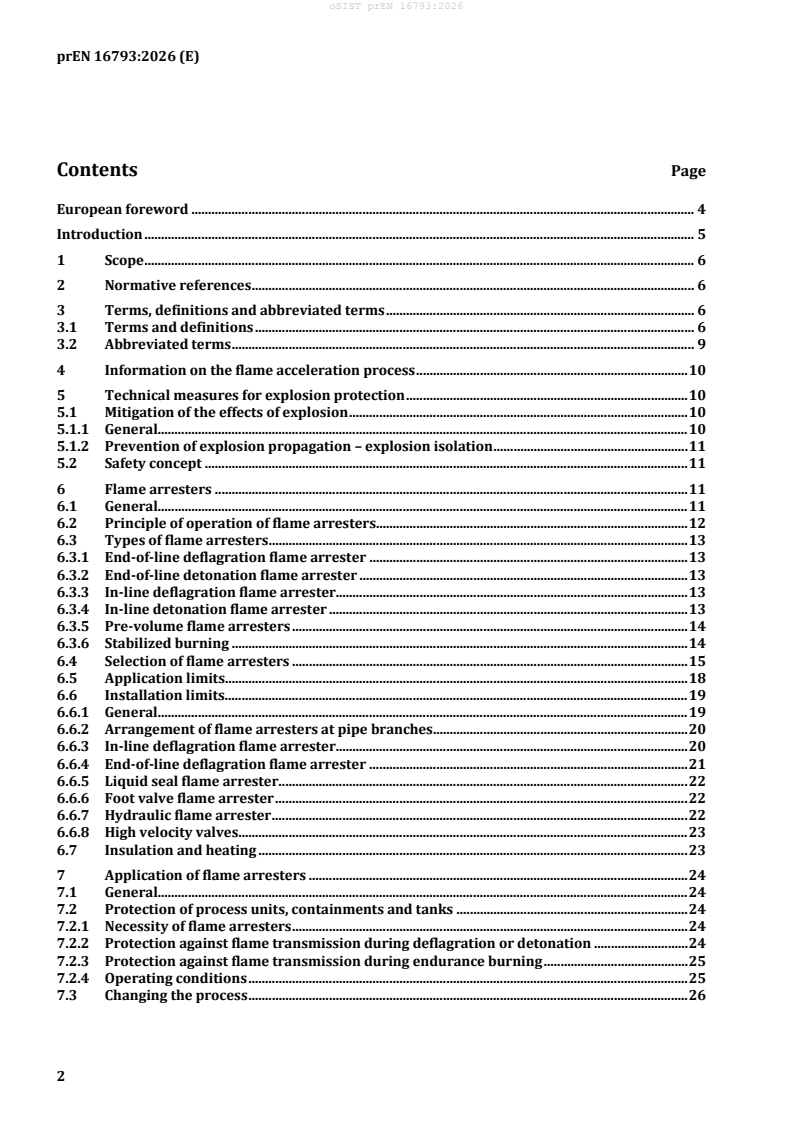
Contents Page
European foreword . 4
Introduction . 5
1 Scope . 6
2 Normative references . 6
3 Terms, definitions and abbreviated terms . 6
3.1 Terms and definitions . 6
3.2 Abbreviated terms . 9
4 Information on the flame acceleration process . 10
5 Technical measures for explosion protection . 10
5.1 Mitigation of the effects of explosion . 10
5.1.1 General. 10
5.1.2 Prevention of explosion propagation – explosion isolation . 11
5.2 Safety concept . 11
6 Flame arresters . 11
6.1 General. 11
6.2 Principle of operation of flame arresters. 12
6.3 Types of flame arresters . 13
6.3.1 End-of-line deflagration flame arrester . 13
6.3.2 End-of-line detonation flame arrester . 13
6.3.3 In-line deflagration flame arrester. 13
6.3.4 In-line detonation flame arrester . 13
6.3.5 Pre-volume flame arresters . 14
6.3.6 Stabilized burning . 14
6.4 Selection of flame arresters . 15
6.5 Application limits . 18
6.6 Installation limits . 19
6.6.1 General. 19
6.6.2 Arrangement of flame arresters at pipe branches. 20
6.6.3 In-line deflagration flame arrester. 20
6.6.4 End-of-line deflagration flame arrester . 21
6.6.5 Liquid seal flame arrester . 22
6.6.6 Foot valve flame arrester . 22
6.6.7 Hydraulic flame arrester . 22
6.6.8 High velocity valves . 23
6.7 Insulation and heating . 23
7 Application of flame arresters . 24
7.1 General. 24
7.2 Protection of process units, containments and tanks . 24
7.2.1 Necessity of flame arresters . 24
7.2.2 Protection against flame transmission during deflagration or detonation . 24
7.2.3 Protection against flame transmission during endurance burning . 25
7.2.4 Operating conditions . 25
7.3 Changing the process . 26
8 Installation, operating and maintenance . 26
8.1 General . 26
8.2 Safety information . 27
8.3 Checking and installing . 27
8.4 Inspection and maintenance intervals . 28
8.5 Liquid seal flame arrester . 28
9 Commissioning checklist . 28
Annex A (informative) Example of a safety concept . 30
Annex B (informative) Guidelines for the arrangement of flame arresters at pipe branches . 32
Bibliography . 34
European foreword
This document (prEN 16793:2026) has been prepared by Technical Committee CEN/TC 305 “Potentially
explosive atmospheres – Explosion prevention and protection”, the secretariat of which is held by DIN.
This document will supersede CEN/TR 16793:2016.
This document prEN 16793:2026 includes the following significant technical changes with respect to
CEN/TR 16793:2016:
— change from Technical Report to European Standard;
— change of references from EN ISO 16852 to EN ISO/IEC 80079-49;
— shortening of Clause 4;
— clarifications throughout the document.
Introduction
The document provided is general in nature and for specific applications further expert advice should be
sought.
In addition to the content of operating manuals from manufacturers, the local accident prevention
regulations, environmental protection and general safety provisions for the devices’ area of use, as well
as relevant laws and national directives, this paper will support the user for a proper use of flame
arresters.
In Europe, the “Directive 2014/34/EU on equipment and protective systems intended for use in
potentially explosive atmospheres” (ATEX – Atmosphères Explosibles) is mandatory for the production
and test intended for use of products in potentially explosive atmospheres. Flame arresters are defined
as a Protective System.
Flame arresters should be tested according to EN ISO/IEC 80079-49, Explosive atmospheres — Part 49:
Flame arresters — Performance requirements, test methods and limits for use, to fulfill the health and safety
requirements of this directive.
Flame arresters are subjected to an EC type examination and are designed for use in areas at risk from
explosion.
The Directive 1999/92/EC of the European Parliament and of the Council of 16 December 1999 on
minimum requirements for improving the safety and health protection of workers potentially at risk from
explosive atmospheres – gives the minimum requirements for the improvement of health protection and
safety of employers who could be endangered by explosive atmospheres. The main issues are assessment
of explosion risk, zone classification and the explosion protection documents (including requirements for
personnel to do engineering, equipment selection, installation, maintenance, repair, etc.).
National regulations and/or codes relating to specific industries or applications can exist.
Flame arresters are required to protect against many types of explosion events within equipment.
The safety obtained depends heavily upon correct selection, installation and maintenance of the flame
arrester. This cannot be achieved without responsible, informed management.
1 Scope
This document is aimed primarily at persons who are responsible for the safe design and operation of
installations and equipment using flammable liquids, vapours or gases.
This document applies to both industrial and mining applications.
This document describes possible risks and gives proposals for the protection against these risks by the
use of flame arresters.
This document gives some guidance for the selection and installation of flame arresters according to
EN ISO/IEC 80079-49 for different common scenarios and it gives best practice for the installation and
maintenance of these flame arresters.
This document is applicable to pressures ranging from 80 kPa to 160 kPa and temperatures ranging from
−20 °C to +200 °C.
2 Normative references
The following documents are referred to in the text in such a way that some or all of their content
constitutes requirements of this document. For dated references, only the edition cited applies. For
undated references, the latest edition of the referenced document (including any amendments) applies.
EN ISO/IEC 80079-49:2024, Explosive atmospheres — Part 49: Flame arresters — Performance
requirements, test methods and limits for use (ISO/IEC 80079-49:2024)
3 Terms, definitions and abbreviated terms
3.1 Terms and definitions
For the purposes of this document, the following terms and definitions given in EN ISO/IEC 80079-49
and the following apply.
ISO and IEC maintain terminology databases for use in standardization at the following addresses:
— ISO Online browsing platform: available at https://www.iso.org/obp/
— IEC Electropedia: available at https://www.electropedia.org/
3.1.1
end-of-line flame arrester
flame arrester that is fitted with one pipe connection only
[SOURCE: EN ISO/IEC 80079-49:2024, 3.21]
3.1.2
explosion
abrupt oxidation or decomposition reaction producing an increase in temperature, pressure, or in both
simultaneously
[SOURCE: ISO 8421-1:1987, 1.13]
3.1.3
explosion group
equipment group
classification system of equipment related to the explosive atmosphere for which they are intended to be
used
[SOURCE: EN ISO/IEC 80079-49:2024, 3.12.3]
Note 1 to entry: While in a large part of the safety equipment industry “explosion group” is used, the mandatory
term to be used in the standards of IEC/TC 31 is “equipment group”.
3.1.4
explosion-pressure-resistant
property of vessels and equipment designed to withstand the expected explosion pressure without
becoming permanently deformed
[SOURCE: EN 13237:2024, 3.31.1]
3.1.5
explosion-pressure-shock resistant
property of vessels and equipment designed to withstand the expected explosion pressure without
rupturing, but allowing permanent deformation
[SOURCE: EN 13237:2024, 3.31.2]
3.1.6
deflagration
explosion propagating at subsonic velocity
[SOURCE: ISO 8421-1:1987, 1.11]
3.1.7
detonation
explosion propagating at supersonic velocity and characterized by a shock wave
[SOURCE: ISO 8421-1:1987, 1.12]
3.1.8
stable detonation
detonation progressing through a confined system without significant variation of velocity and pressure
characteristics
Note 1 to entry: For the atmospheric conditions, test mixtures and test procedures of this document, typical
velocities range between 1 600 m/s and 2 200 m/s.
[SOURCE: EN ISO/IEC 80079-49:2024, 3.10]
3.1.9
unstable detonation
detonation during the transition of a combustion process from a deflagration into a stable detonation
Note 1 to entry: The transition occurs in a limited spatial zone, where the velocity of the combustion wave is not
constant and where the explosion pressure is significantly higher than in a stable detonation. The position of this
transition zone depends, amongst other factors, on pipe diameter, pipe configuration, test gas and explosion group.
Note 2 to entry: An unstable detonation presents a higher level of hazard than a stable detonation due to higher
flame speeds and pressures.
[SOURCE: EN ISO/IEC 80079-49:2024, 3.11]
3.1.10
flame arrester
device fitted to the opening of an enclosure, or to the connecting pipe work of a system of enclosures, and
whose intended function is to allow flow but prevent the transmission of flame
[SOURCE: EN ISO/IEC 80079-49:2024, 3.1]
3.1.11
flame arrester element
portion of a flame arrester whose principal function is to prevent flame transmission
[SOURCE: EN ISO/IEC 80079-49:2024, 3.3]
3.1.12
in-line flame arrester
flame arrester that is fitted with two pipe connections, one on each side of the flame arrester
[SOURCE: EN ISO/IEC 80079-49:2024, 3.22]
3.1.13
mixture
used to represent any mixtures of gas and/or product vapour/air
3.1.14
product
equipment, protective systems, safety devices, components and their combinations
3.1.15
protected side
side of the plant component to be protected
3.1.16
protective system
autonomous devices to stop an explosion immediately and/or limit the effects of explosion flames and
pressures
3.1.17
stabilized burning
steady burning of a flame stabilized at, or close to, the flame arrester element [short time (max.
30 minutes) or endurance burning (for unlimited time)]
3.1.18
unprotected side
ignition source side
3.1.19
restriction
reduction of the diameter of the pipe on the protected side of a flame arrester
Note 1 to entry: For example, a restriction can be a not fully opened valve.
3.2 Abbreviated terms
For the purposes of this document, the following abbreviated terms apply.
DN nominal size of the connection of a device or pipe fitting
LEL lower explosion limit of the explosion range
L pipe length on the protected side
p
L pipe length between flame arrester and restriction
r
L pipe length on the unprotected side, maximum allowable run-up length for installation
u
p maximum operational pressure
T maximum operational temperature
MESG maximum experimental safe gap – safe gap measured in accordance with EN ISO/IEC 80079-
20-1
p/v valve pressure and vacuum relief vent valve
UEL upper explosion limit of the explosion range
NPSH net positive suction head
Z minimum operational water seal immersion depth when the mixture flow displaces the
0min
water from the immersion tubes, where Z > Z
0min Rmin
Z operational immersion depth, corresponding to Z plus the manufacturer's recommended
0 0min
safety margin
Z minimum water seal immersion depth at rest above the outlet openings of the immersion
Rmin
tubes
Z immersion depth at rest, corresponding to Z plus the manufacturer's recommended
R Rmin
safety margin
safe volume flow rate
V
max
safe volume flow rate including a safety margin
V
s
t burn time
BT
4 Information on the flame acceleration process
A simplified representation of the flame acceleration process in a straight pipe is presented in Figure 1.
Key
X pipe distance 3 deflagration
Y1 flame speed 4 unstable detonation
Y2 pressure 5 stable detonation
1 flame speed
2 pressure
Figure 1 — Development of an explosion in a pipeline
5 Technical measures for explosion protection
5.1 Mitigation of the effects of explosion
5.1.1 General
In case it is not possible to prevent the ignition of an explosive atmospheres, measures shall be taken to
reduce the effects of an explosion to an acceptable extent. Such measures are:
— explosion-resistant design;
— explosion relief;
— explosion suppression;
— prevention of flame and explosion propagation.
5.1.2 Prevention of explosion propagation – explosion isolation
An explosion occurring in one part of a plant can propagate to upstream and downstream parts, where it
can cause further explosions. Acceleration caused by plant fittings or propagation in pipes can intensify
the explosion effects. The explosion pressures can be much higher than the maximum explosion pressure
under normal conditions and can destroy items of plant even if they are of explosion pressure resistant
or explosion pressure shock resistant design. It is therefore important to limit possible explosions to
single parts of the plant. This is achieved by explosion isolation. Explosion isolation can be performed,
e.g. by flameproof closed isolation valves or with flame arresters.
5.2 Safety concept
An example for a safety concept is given in the informative Annex A.
6 Flame arresters
6.1 General
The purpose of a flame arrester is to allow gas to pass through but stop a flame in order to prevent an
explosion or fire propagation. There are many different situations in which flame arresters are applied.
Flame arresters are designed to meet specific requirements of applications.
The severity of explosion depends on the operating conditions, the physical piping conditions, and
environmental factors. Flame arresters are designed for specific applications. Therefore, a wide variety
of flame arrester types are available.
The user shall ensure that a flame arrester is suitable for conditions that match or exceed the intended
application.
Figure 2 shows possible and typical locations of flame arresters, for example:
— tanks;
— processing systems;
— vapour combustion systems, incinerators, flares;
— ships, offshore platforms, vehicles and loading systems;
— vapour recovery units;
— as integrated components of pumps, blowers and other rotating machines.
Figure 2 — Typical locations for flame arresters
6.2 Principle of operation of flame arresters
Depending on the selected technical solution to prevent flame transmission flame arrester types
according to Table 3 are available.
Table 3 — Flame arrester principle
Types of flame arresters Safeguard principle Remark
Static flame arrester Flame quenching measurable type; flame arrester
element with quenching gaps that
can be drawn, measured and
controlled
non-measurable type; flame
arrester element with quenching
gaps that cannot be drawn,
measured or controlled
Liquid product detonation Prevention of flame transmission liquid seal flame arrester;
flame arrester at a barrier formed by the liquid
foot valve flame arrester
product
Hydraulic flame arrester Prevention of flame transmission —
at a barrier formed by liquid
Dynamic flame arrester Nominal flow velocity at the outlet high-velocity pressure relief valve
exceed flame velocity thus prevent
flame transmission
6.3 Types of flame arresters
6.3.1 End-of-line deflagration flame arrester
End-of-line deflagration flame arresters are used to stop flames coming from outside and avoid explosion
entering the pipe work or tank.
End-of-line deflagration flame arresters are designed to stop atmospheric deflagrations.
6.3.2 End-of-line detonation flame arrester
End-of-line detonation flame arresters are devices in liquid product lines to protect the filling and
emptying line of a tank.
6.3.3 In-line deflagration flame arrester
In-line deflagration flame arresters are designed and tested for stopping deflagrations propagating in a
pipeline.
6.3.4 In-line detonation flame arrester
Type 1 flame arresters for unstable detonations with restriction on the protected side are designed,
tested and certified for stopping deflagrations and unstable detonations. These type 1 detonation flame
arresters are labelled DET1 on the warning label and in the manufacturer's documentation.
Type 2 flame arresters for unstable detonations without restriction on the protected side are designed,
tested and certified for stopping deflagrations and unstable detonations. These type 2 detonation flame
arresters are labelled DET2 on the warning label and in the manufacturer's documentation.
Type 3 flame arresters for stable detonations with restriction on the protected side are designed, tested
and certified for stopping deflagrations and stable detonations. These type 3 detonation flame arresters
are labelled DET3 on the warning label and in the manufacturer's documentation.
Type 4 flame arresters for stable detonations without restriction on the protected side are designed,
tested and certified for stopping deflagrations and stable detonations. These type 4 detonation flame
arresters are labelled DET4 on the warning label and in the manufacturer's documentation.
Type 1 detonation flame arresters are also suitable for use as Type 2, Type 3 and Type 4.
Type 2 detonation flame arresters are also suitable for use as Type 4.
Type 3 detonation flame arresters are also suitable for use as Type 4.
6.3.5 Pre-volume flame arresters
Pre-volume flame arresters are flame arresters that, after ignition by an internal source, prevent flame
transmission from inside a containment that in terms of size or volume does not coincide with the size or
volume of the nominal size of the pipe, which is connected to the flame arrester during testing (e.g. a
DN50 pipe with a DN50 flame arrester).
EXAMPLE Reactors, carbon absorption filters.
NOTE Flares, compressors and fans can necessitate special equipment.
6.3.6 Stabilized burning
6.3.6.1 Short time burning flame arresters
For operation conditions leading to stabilized burning of the mixtures directly on the flame arrester
element, there will be only limited safety against stabilized burning, i.e. flame transmission protection.
Then flame arresters can be fitted with temperature sensors to detect the flame and trigger measures to
suppress the stabilized burning (e.g. emergency functions such as switching the plant off/over, inerting,
etc.) within half the time for which the flame arrester is resistant to short time burning.
A temperature sensor shall be designed for measuring temperatures both in liquid and gaseous media. A
common design is a resistance thermometer with a PT100 measuring resistance. The length of the probe
depends on the flame arrester design and its function should be tested with the flame arrester according
to the standard for flame arresters. The temperature sensor shall be suitable for the operation in the
respective explosive atmosphere.
A temperature sensor shall respond within half of the time for which the flame arrester is safe against
short-time burning. It shall be ensured that the flame is permanently quenched (without re-ignition of
the flame) within half the time for which the flame arrester is resistant to short time burning.
The system for preventing stabilized burning shall activate after the trigger temperature (to be set in each
instance) is exceeded. Adherence to the permitted response time for activation shall be ensured. The
trigger temperature may be no more than 60 K above the operating temperature for the flame arrester.
It is recommended a trigger temperature of 20 K above the maximum operating temperature. For heated
flame arresters it is recommend a trigger temperature of 30 K to 40 K above the maximum operating
temperature.
A fire with high temperatures can destroy the measuring resistance (PT100). Exchange the measuring
probe, if the flame temperature exceeded the operating temperature of the temperature sensor.
If the operating company installs any temperature sensors of their own supply, these shall comply with
the safety specifications of the temperature sensor tested with the flame arrester and shall be ATEX rated.
It further shall be proven that in the event of short time burning the same response times are met and (in
the case of in-line deflagration and detonation arresters) the mechanical strength matches that of the
model approved.
6.3.6.2 End-of-line endurance burning flame arrester
End-of-line endurance burning flame arresters are designed and tested for stopping both atmospheric
deflagrations and flame transmission in case of stabilized burning for unlimited time (endurance
burning).
6.4 Selection of flame arresters
Flame arresters should be selected for the intended use (see Figure 3). For the correct selection of a flame
arrester an assessment should be carried out to identify:
— what should be protected;
— where the potential ignition sources are;
— where an explosive atmosphere may arise;
— what kind of explosive atmosphere can occur;
— operating parameters (temperature, pressure, etc.) of the explosive atmosphere:
— the geometries of the pipework and vessel (e.g. nominal sizes, lengths, volumes).
NOTE 1 For additional information, see also EN ISO/IEC 80079-49:2024, Annex B.
Flame arresters are designed and tested to meet particular operating conditions. To ensure that an
effective flame arrester is selected, it is essential that the conditions in which it will be used are specified
carefully (see Figure 4).
A first selection is to decide whether to use an end-of line or an in-line flame arrester. In some special
applications, pre-volume flame arresters are used to prevent flame transmission from inside an
explosion-pressure-resistant containment (e.g. a vessel or closed pipe work) to the outside, or into the
connecting pipe work. A typical application for end-of-line flame arrester is the protection of storage
tanks for flammable liquids against atmospheric deflagrations initiated by lightning strikes or other
external ignition sources.
Openings of explosion-pressure-resistant or explosion-pressure-shock resistant plant components
where explosions can occur internally shall be equipped with pre-volume deflagration flame arresters to
prevent an explosion transmission from the inside to the outside if they are connected to other plants
which are not explosion-pressure-resistant or explosion-pressure-shock resistant. If flammable mixtures
are emitted or processed during operation in relatively large volumes and over a relatively long period
(e.g. when filling a tank or vapour processed to a vapour destruction unit), it shall be anticipated that
after any ignition there may be stabilized burning at the flame arrester element. In such cases, suitable
additional measures need to be taken to protect the plants, if the installed flame arrester is not designed
/ approved for stabilized burning.
Stabilized burning for out-breathing tanks is a risk. Depending on the duration of the steady flow out, an
endurance burning or a short time burning flame arrester shall be selected. The maximum time a short
time burning proof flame arrester will withstand a stabilized flame is marked on the marking plate as
burning time (t ) and ranging between 1 min and 30 min. It shall be taken into account that the time
BT
needed to fill a tank can be many hours.
The selection of in-line flame arresters depends on the distance between the identified ignition source
and the installation location of the flame arrester. Deflagration flame arresters are designed and tested
for limited distance in accordance with the IOM (Installation and Operating Manual) of the manufacturer
(maximum L /D = 50 for explosion groups IIA1, IIA, IIB1, IIB2 and IIB3 and L /D = 30 for explosion
u u
groups IIB and IIC). For applications with longer distances or where the location of the ignition source is
not identified, deflagration arresters shall not be used.
For stabilized burning of mixtures due to the operating conditions directly at the flame arrester element
a flashback can only be prevented for a limited period of time. Therefore, additional safety measures are
necessary. This time limited safety against stabilized burning generally applies to most in-line flame
arresters. If due to special operating conditions stabilized burning of mixtures is possible at the flame
arrester element – this includes for example the application within closed pipeline systems of process-
technical plants with operationally force-actuated volume flows – flame arresters with integrated
temperature sensors shall be used, in order to trigger an alarm to start measures to stop the stabilized
burning on the element (by a shut down or by-pass, inerting, etc.). For stabilized burning check the
likelihood on which side or on both sides it may burn and a temperature sensor(s) shall then be installed
accordingly – either on one side only or on both sides.
Figure 3 — Selection of flame arresters
After selection of the flame arrester type the explosive atmosphere should be checked (see Figure 5).
Flammable vapour and gases are classified in Explosion Groups by means of the safety classification
number Maximum Experimental Safe Gap (MESG). MESG is independent of the actual gap size (also called
gap width or gap height) of a static flame arrester’s element. EN ISO/IEC 80079-49 classifies into the
explosion groups according to Table 4.
Table 4 — Explosion groups and the corresponding MESG
Explosion group Maximum experimental safe gap
mm
a
IIA1 ≥ 1,14
IIA ≥ 0,90
IIB1 ≥ 0,85
IIB2 ≥ 0,75
IIB3 ≥ 0,65
IIB > 0,5
IIC ≤ 0,5
a
Group IIA1 was previously designated as Group I.
NOTE 2 MESG is a safety characteristic of the material and depends on the measurement system. In this
document, the MESG is determined according to EN ISO/IEC 80079-20-1; other methods can give different results.
The determination of the MESG of the process media is the responsibility of the user of a flame arrester. Flame
arresters are tested with vapours/gases of the respective explosion group and are marked accordingly. The
application is limited to mixtures with an MESG equal to or greater than that tested.
Mixtures which tend to self-decompose (e.g. acetylene), are chemically unstable, and mixtures with
higher oxygen concentration or another oxidizing agent than oxygen (chlorine as oxidant, etc.) are
excluded from the standard approval procedure according to EN ISO/IEC 80079-49. Carbon disulphide
is also excluded. Flame arresters intended for the mentioned gas mixtures shall be tested with the special
mixture directly and be marked accordingly.
Flame arresters according to EN ISO/IEC 80079-49 are designed and tested for gas/air or vapour/air
mixtures, not for oxygen enriched mixtures or self-decomposing substances. The explosion group shall
be verified depending on the components of the mixture. To be on the safe side, the explosion group of
the component with the smallest MESG value may be used. Other methods and models are available to
estimate the MESG of the worst-case gas mixture composition. In case of any doubt, it is recommended to
contact the manufacturer of flame arrester.
Figure 4 — Categorization of explosive gas mixtures
6.5 Application limits
The marking of a flame arrester according to EN ISO/IEC 80079-49 contains, amongst others, application
limits as shown in Table 5. Ensure that this and the further data specified according to Table 6 conform
to the intended operating conditions. According to EN ISO/IEC 80079-49 the warning “flame arresters
have installation and application limits” shall be marked on the flame arrester.
NOTE Flame arresters for special purposes can have different application limits.
Table 5 —Application limits marked on the flame arrester according to EN ISO/IEC 80079-49
Protected side (for uni-directional flame arresters)
Explosion group of the gas, starting with the sign
Maximum operating temperature T
Maximum operating pressure p
Type designation:
“DEF” for deflagration flame arresters in combination with maximum allowable L /D for in-line flame
u
arresters
“DET” for detonation flame arresters in combination with the type number “1” to “4” (see Figure 3)
“BC” for burn rating in combination with the burn classification “a”, “b” or “c”.
“a” – endurance burn (no time limit)
“b” – short time burn from 1 min to 30 min
“c” – not burn time
In case of class b the burn time t in minutes the flame arrester was tested for (from 1 min to max.
BT
30 min) shall be given.
Maximum flow rate for hydraulic flame arresters
Table 6 — Further application limits
Application limits Remarks
Working direction for in-line flame arresters Directional (the protected side shall be marked) or
bi-directional
Oxygen concentration Flame arresters are tested for mixtures with air
normally. Air has approximate 21 vol. % oxygen
(O ). Flame arresters for oxygen-enriched mixtures
shall be tested and approved accordingly
Housing test pressure Necessary for in-line flame arrester to know the
14.4 of EN ISO/IEC 80079-49:2024) maximum test pressure for which the housing is
6 approved
for deflagration flame arresters ≥ 1,1 ⋅ 10 Pa
(10 Pa = 1 MPa = 10 bar)
for detonation flame arresters ≥ 10 × p
Endurance burning (static flame arresters) The safe use is limited to pure hydrocarbons,
admissible use for other chemicals (e.g. alcohols,
ketones, etc.) shall be explicitly tested.
Endurance burning is guaranteed for a specified
installation position only under atmospheric
conditions (P ≤ 0,11 MPa, T ≤ 60 °C) at the flame
arresting element
Maximum suction rate for emptying Shall be observed for liquid product detonation
flame arresters
Material resistance When selecting the flame arrester, the user shall
ensure that they are sufficiently resistant (e.g.
against corrosion) with regard to the substances
present in the system. This also applies to possible
coatings.
Information in this matter the user can find in the
instruction for use.
6.6 Installation limits
6.6.1 General
This clause includes information about specific types of flame arresters and specific installation based on
experience. Where limited knowledge is available guidance is not provided.
Installation limits apply; these are summarized in Table 7.
Table 7 — Installation limits
Installation limits Remarks
Installation orientation Arresters may have limits on their installation orientation. The worst
case for in-line flame arresters under stabilized burn condition is flow
vertically downwards and potential ignition source from below. The
user shall take into account the instructions for use given by the
manufacturer.
Combination of installation Flame arrester shall not be combined with machines (e.g. compressor,
combustion engines, ventilator) without previous additional
assessment. Due to the pressures, temperatures, flow velocities,
volumina and/or turbulences in the pipe branches such specific
considerations are necessary.
Plugging Plugging, e.g. accumulation of condensate due to incorrect installation
can lead to uncertain operating conditions; the plants operating
pressure could be exceeded.
Max. permitted L /D ratio L /D is the ratio between pipeline length on the unprotected side and
u u
the nominal pipe size.
Min. required L /D For deflagration arrester and for detonation arrester type 2 and type 4
p
the distance to any later restricion is case-specific.
Nominal pipe sizes The nominal sizes of the pipelines connected on the side of the ignition
source (unprotected side) shall be less or equal to the flame arresters’
nominal size.
The nominal sizes of the pipelines connected on the protected side shall
be equal to or larger than the nominal size on the unprotected side.
6.6.2 Arrangement of flame arresters at pipe branches
Guidelines for the arrangement of flame arresters at pipe branches are given in the informative Annex B.
6.6.3 In-line deflagration flame arrester
In-line deflagration flame arresters are designed and tested for stopping deflagrations propagating in a
pipeline. For in-line deflagration flame arresters the maximum allowable L /D ratio according to
u
EN ISO/IEC 80079-49 is listed in Table 8 and an example is shown in Figure 5.
Table 8 — Maximum permitted L /D ratio (EN ISO/IEC 80079-49:2024, 7.3.2.2)
u
Pipe length Explosion group
L /D ≤ 50 IIA1, IIA, IIB1, IIB2, IIB3
u
L /D ≤ 30 IIB, IIC
u
The ratio of pipe length (distance between the potential ignition source and the location of the flame
arrester) and pipe diameter shall not exceed the tested ratio L /D.
u
Key
1 side of potential ignition source
2 unprotected side
3 protected side
Figure 5 — Installation limits for deflagration flame arresters
To calculate the maximum allowable pipe length, take the permitted Lu/D ratio for your flame arrester
and use the formula:
DN ×L /D
u
L= (1)
where
L is pipe length (m);
D is nominal pipe diameter (mm).
EXAMPLE For a flame arrester with DN 150 and a maximum allowable L /D = 50 the maximum pipe length is
u
7,5 m.
There shall be no reduction of pipe diameter between the potential ignition source and a deflagration
flame arrester unless it is written in the instruction for use given by the manufacturer and the operating
manual. Shut-off valves can be installed in a pipeline if they are full open during operation and do not
reduce the free flow area. Pipe branches and valves on the unprotected side shall be installed as close as
possible to the in-line deflagration flame arrester. For in-line deflagration flame arresters at least 10 %
of the cross-sectional area of the pipe shall be open at the ignition source. This provides a safety factor
compared to the tested configuration. In-line deflagrat
...