

FprEN 17420
(Main)Railway applications - Vehicle front design for trams with respect to pedestrian safety
- Abstract
This document is applicable to tram vehicles in accordance with EN 17343. Tram-train vehicles, on track machines, infrastructure inspection vehicles and road-rail machines in accordance with EN 17343 and demountable machines/machinery are not in the scope of this document.
This document describes passive safety measures to reduce the consequences of collisions with pedestrians. These measures provide the last means of protection when all other possibilities of preventing an accident have failed, i.e.:
— design provisions for the vehicle front to minimize the impact effect on a pedestrian when hit;
— design provisions for the vehicle front for side (lateral) deflections in order to minimize the risk of being drawn under the vehicle on flat ground (embedded track);
— design provisions for the vehicle body underframe to not aggravate injuries to a pedestrian/body lying on the ground;
— provisions to prevent the pedestrian from being over-run by the leading wheels of the vehicle.
This document focuses on the consequences of the primary and tertiary impact. The consequences of a secondary impact are out of the scope of this document.
The following measures to actively improve safety are not in the scope of this document:
— colour of front;
— additional position lights;
— additional cameras;
— driver assistance systems;
— additional acoustic warning devices, etc.;
— view of the driver / mirrors;
— consequences for pedestrian injuries due to secondary impact with infrastructure (side posts, concrete ground, poles, trees, etc.).
The provisions of this document only apply to new vehicles.
- Status
- Not Published
- Publication Date
- 24-Mar-2027
- Technical Committee
- CEN/TC 256 - Railway applications
- Drafting Committee
- CEN/TC 256/WG 2 - Structural requirements

FprEN 17420 is a draft European Standard from CEN for railway applications. It specifies passive design measures, assessment methods, and validation tests for the front of tram vehicles to reduce the consequences of collisions with pedestrians. The document is for tram vehicle designers, manufacturers, assessors, and test teams that need to shape, simulate, and verify the vehicle front for pedestrian safety.
What does FprEN 17420 specify?
FprEN 17420 applies to tram vehicles in accordance with EN 17343 and only to new vehicles. It covers passive safety measures for pedestrian collisions, with a focus on the primary impact and tertiary impact phases, and it excludes tram-train vehicles, on-track machines, infrastructure inspection vehicles, road-rail machines, and demountable machines/machinery.
The standard is organized into:
- Clause 1 Scope
- Clause 2 Normative references
- Clause 3 Terms and definitions
- Clause 4 Symbols and abbreviations
- Clause 5 Front design of tram vehicles
- Clause 6 Reference collision scenario type A
- Clause 7 Reference collision scenario type B
- Annex A, informative, PACM test protocol report
| Annex | What it covers |
|---|---|
| Annex A | Informative PACM test protocol report for documenting run-over tests |
The document describes how to design the tram front so a pedestrian is deflected sideways rather than run over, how to check the geometry of the front end, when numerical simulation may be used, and how to validate a pedestrian anti-crush mechanism (PACM) with tests.
What are the key requirements of FprEN 17420?
FprEN 17420 sets out a design-and-validation route for the front end of a tram vehicle. In practice, the designer first tries to meet the geometric rules in Clause 6, then uses numerical simulation if those geometry targets cannot all be met, and finally uses run-over tests in Clause 7 for recumbent-pedestrian protection.
Front design objective and collision scenarios
Clause 5 says the tram vehicle front shall be designed to reduce severe injury, trapping under the vehicle, contact with underfloor equipment, and wheel run-over. The document separates the collision into primary, secondary, and tertiary phases, and uses two reference scenarios:
- Type A: a passing pedestrian in front of the vehicle
- Type B: a lying pedestrian on the ground in front of the vehicle
This matters because the geometry and validation method differ depending on whether the pedestrian is struck while standing or is already on the ground.
Type A geometry for a passing pedestrian
Clause 6 defines the impact surface as the central 50 % of vehicle width, and the extended impact surface as the adjacent band up to 75 % of vehicle width. These zones are the areas that must be checked for front-shape compliance.
The key geometric criteria in Clause 6 are:
- the front shape shall support lateral deflection rather than run-over
- the foremost points on the front should keep the pedestrian contact height low, with h limited to 350 mm
- the angles beta and gamma shall each be at least 10°
- the tolerance bands dB and dG shall stay within the stated limits on the impact surface
In practice, this means the vehicle nose, skirts, and front fairings need to be shaped so the pedestrian is steered sideways instead of being pushed downward under the vehicle.
Edges, cut-outs, and front details
Clause 6 also limits local injury points on the impact surface and extended impact surface. Exposed rigid edges need sufficient rounding, cut-outs are restricted, and coupling elements shall be covered. Rear-view cameras or mirrors shall be positioned above 1 750 mm.
This matters because even when the overall shape is compliant, a sharp edge, an uncovered coupling, or a low-mounted device can create a local injury hazard.
Numerical simulation when geometry alone is not enough
Clause 6.4 allows numerical simulation if the geometric requirements cannot all be achieved. The simulation must use validated models, and the model validation is checked against dynamic test results with a maximum 20 % deviation.
The reference simulation uses:
- a vehicle at design mass in running working order
- 20 km/h impact speed
- a stationary 50th percentile male pedestrian model
- two impact positions: at 15 % and 50 % of half vehicle width
This means the standard does not treat simulation as free-form analysis. It requires validated models, defined pedestrian posture, defined vehicle parts in the model, and specific comparison points.
Type B validation for a recumbent pedestrian
Clause 7 addresses the lying pedestrian case and allows the use of a low front skirt or a PACM. The PACM examples named in the standard are a pedestrian deflector, a trap basket, and a drop-down tray.
Clause 7.4 requires validation tests on embedded track only, using an emergency-braking run at 25 km/h with the mannequin placed 4.0 m ahead of the braking point. Four test positions are required for the adult rescue mannequin and four for the child rescue mannequin.
The test outcome has three main pass conditions:
- no limbs, chest, or head severed
- no limbs, chest, or head crushed
- no contact with the wheels
In practice, this is the evidence package for proving that a tram front and PACM protect a person who has fallen onto the track.
Test documentation
Clause 7.4.5 requires three deliverables: a PACM description, a PACM test protocol report, and a conclusion for each of the eight tests. Annex A provides an example structure for the test protocol report, including photos, video, track data, vehicle data, mannequin data, and the condition of the PACM after impact.
What terms does FprEN 17420 define?
- Tram vehicle - an urban rail vehicle designed to run on a tram network.
- Collision scenario - an accident-derived scenario used for design and assessment.
- Head injury criterion (HIC) - an impact metric for head injury likelihood; the document uses it as the main injury indicator in Clause 6.
- Tram system - an urban rail system operated on shared road-traffic infrastructure and/or its own infrastructure.
- Rescue mannequin - a life-size model used in tests to simulate what happens to a person in a pedestrian accident.
- Anthropomorphic test device (ATD) - a human model or mannequin used in tests.
- Pedestrian anti-crush mechanism (PACM) - a device intended to prevent a pedestrian from being crushed.
- Vehicle width (VW) - the overall vehicle width excluding additionally fixed equipment such as mirrors and cameras.
Who uses FprEN 17420?
FprEN 17420 is used by tram vehicle manufacturers, vehicle body designers, and system integrators who shape the front end of new vehicles. It is also used by simulation engineers, test laboratories, safety assessors, and conformity teams that need to verify pedestrian-impact performance.
Buyers, fleet owners, and specification writers use it when they need to state front-end pedestrian-safety requirements for new tram vehicles. It is relevant to urban rail and light rail projects where pedestrian interaction is part of the operating environment.
What changed in FprEN 17420 from the previous edition?
FprEN 17420:2025 will supersede CEN/TR 17420:2020.
Which standards are used with FprEN 17420?
FprEN 17420 cites two normative references in Clause 2:
- EN 15663:2017+A2:2024 - provides vehicle reference masses and is used for the design mass in running working order, which is central to both the geometric assessment and the test conditions.
- EN 17343:2023 - provides general terms and definitions for railway applications and defines the tram-vehicle context used throughout the standard.
The text also points to TB 024:2021-11 in the numerical-simulation clause as the basis for the pedestrian model certification reference used there.
What does the FprEN 17420 document contain?
FprEN 17420 contains a clause structure that combines design guidance, geometric assessment, numerical simulation, and full-scale validation testing. Clause 6 includes the front-surface definitions, evaluation points, geometric parameters, criteria for angles and heights, and the recommended assessment sequence. It also contains the simulation setup, modeling hypotheses, posture specification tables, and acceptance criteria for the pedestrian impact model.
Clause 7 contains the PACM concept, the test vehicle and track conditions, the adult and child rescue mannequin requirements, the four run-over test positions, the test chronology, and the pass/fail criteria. Annex A provides a structured report format for recording PACM test results, with photos, video, vehicle data, mannequin data, and post-impact condition checks.
Relations
- Effective Date
- 18-Jan-2023
Get Certified
Connect with accredited certification bodies for this standard

IRIS Certification (UNIFE)
International Railway Industry Standard certification.

TÜV SÜD Rail GmbH
TÜV SÜD railway certification services.

Bureau Veritas Railway Certification
Railway and transportation certification.
Sponsored listings
Frequently Asked Questions
FprEN 17420 is a draft published by the European Committee for Standardization (CEN). Its full title is "Railway applications - Vehicle front design for trams with respect to pedestrian safety". This standard covers: This document is applicable to tram vehicles in accordance with EN 17343. Tram-train vehicles, on track machines, infrastructure inspection vehicles and road-rail machines in accordance with EN 17343 and demountable machines/machinery are not in the scope of this document. This document describes passive safety measures to reduce the consequences of collisions with pedestrians. These measures provide the last means of protection when all other possibilities of preventing an accident have failed, i.e.: — design provisions for the vehicle front to minimize the impact effect on a pedestrian when hit; — design provisions for the vehicle front for side (lateral) deflections in order to minimize the risk of being drawn under the vehicle on flat ground (embedded track); — design provisions for the vehicle body underframe to not aggravate injuries to a pedestrian/body lying on the ground; — provisions to prevent the pedestrian from being over-run by the leading wheels of the vehicle. This document focuses on the consequences of the primary and tertiary impact. The consequences of a secondary impact are out of the scope of this document. The following measures to actively improve safety are not in the scope of this document: — colour of front; — additional position lights; — additional cameras; — driver assistance systems; — additional acoustic warning devices, etc.; — view of the driver / mirrors; — consequences for pedestrian injuries due to secondary impact with infrastructure (side posts, concrete ground, poles, trees, etc.). The provisions of this document only apply to new vehicles.
This document is applicable to tram vehicles in accordance with EN 17343. Tram-train vehicles, on track machines, infrastructure inspection vehicles and road-rail machines in accordance with EN 17343 and demountable machines/machinery are not in the scope of this document. This document describes passive safety measures to reduce the consequences of collisions with pedestrians. These measures provide the last means of protection when all other possibilities of preventing an accident have failed, i.e.: — design provisions for the vehicle front to minimize the impact effect on a pedestrian when hit; — design provisions for the vehicle front for side (lateral) deflections in order to minimize the risk of being drawn under the vehicle on flat ground (embedded track); — design provisions for the vehicle body underframe to not aggravate injuries to a pedestrian/body lying on the ground; — provisions to prevent the pedestrian from being over-run by the leading wheels of the vehicle. This document focuses on the consequences of the primary and tertiary impact. The consequences of a secondary impact are out of the scope of this document. The following measures to actively improve safety are not in the scope of this document: — colour of front; — additional position lights; — additional cameras; — driver assistance systems; — additional acoustic warning devices, etc.; — view of the driver / mirrors; — consequences for pedestrian injuries due to secondary impact with infrastructure (side posts, concrete ground, poles, trees, etc.). The provisions of this document only apply to new vehicles.
FprEN 17420 is classified under the following ICS (International Classification for Standards) categories: 13.200 - Accident and disaster control; 45.060.10 - Tractive stock; 45.140 - Metro, tram and light rail equipment. The ICS classification helps identify the subject area and facilitates finding related standards.
FprEN 17420 has the following relationships with other standards: It is inter standard links to CEN/TR 17420:2020. Understanding these relationships helps ensure you are using the most current and applicable version of the standard.
FprEN 17420 is available in PDF format for immediate download after purchase. The document can be added to your cart and obtained through the secure checkout process. Digital delivery ensures instant access to the complete standard document.
Standards Content (Sample)
SLOVENSKI STANDARD
01-julij-2025
Železniške naprave - Sprednja konstrukcija tramvajskih vozil ob upoštevanju
varnosti pešcev
Railway applications - Vehicle front design for trams with respect to pedestrian safety
Bahnanwendungen - Fahrzeugkopfgestaltung von Straßenbahn-/Tramfahrzeugen im
Hinblick auf den Passantenschutz
Applications ferroviaires - Conception de l’extrémité des véhicules de tram en ce qui
concerne la sécurité des piétons
Ta slovenski standard je istoveten z: prEN 17420
ICS:
13.200 Preprečevanje nesreč in Accident and disaster control
katastrof
45.140 Oprema za podzemne vlake, Metro, tram and light rail
tramvaje in lahka tirna vozila equipment
2003-01.Slovenski inštitut za standardizacijo. Razmnoževanje celote ali delov tega standarda ni dovoljeno.
DRAFT
EUROPEAN STANDARD
prEN 17420
NORME EUROPÉENNE
EUROPÄISCHE NORM
May 2025
ICS 13.200 Will supersede CEN/TR 17420:2020
English Version
Railway applications - Vehicle front design for trams with
respect to pedestrian safety
Applications ferroviaires - Conception de l'extrémité Bahnanwendungen - Fahrzeugkopfgestaltung von
des véhicules de tram en ce qui concerne la sécurité Straßenbahn-/Tramfahrzeugen im Hinblick auf den
des piétons Passantenschutz
This draft European Standard is submitted to CEN members for enquiry. It has been drawn up by the Technical Committee
CEN/TC 256.
If this draft becomes a European Standard, CEN members are bound to comply with the CEN/CENELEC Internal Regulations
which stipulate the conditions for giving this European Standard the status of a national standard without any alteration.
This draft European Standard was established by CEN in three official versions (English, French, German). A version in any other
language made by translation under the responsibility of a CEN member into its own language and notified to the CEN-CENELEC
Management Centre has the same status as the official versions.
CEN members are the national standards bodies of Austria, Belgium, Bulgaria, Croatia, Cyprus, Czech Republic, Denmark, Estonia,
Finland, France, Germany, Greece, Hungary, Iceland, Ireland, Italy, Latvia, Lithuania, Luxembourg, Malta, Netherlands, Norway,
Poland, Portugal, Republic of North Macedonia, Romania, Serbia, Slovakia, Slovenia, Spain, Sweden, Switzerland, Türkiye and
United Kingdom.
Recipients of this draft are invited to submit, with their comments, notification of any relevant patent rights of which they are
aware and to provide supporting documentation.
Warning : This document is not a European Standard. It is distributed for review and comments. It is subject to change without
notice and shall not be referred to as a European Standard.
EUROPEAN COMMITTEE FOR STANDARDIZATION
COMITÉ EUROPÉEN DE NORMALISATION
EUROPÄISCHES KOMITEE FÜR NORMUNG
CEN-CENELEC Management Centre: Rue de la Science 23, B-1040 Brussels
© 2025 CEN All rights of exploitation in any form and by any means reserved Ref. No. prEN 17420:2025 E
worldwide for CEN national Members.
prEN 17420:2025 (E)
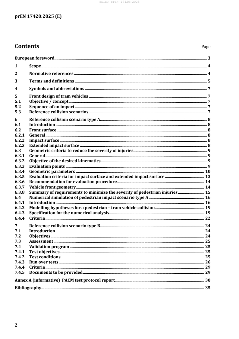
Contents Page
European foreword . 3
1 Scope . 4
2 Normative references . 4
3 Terms and definitions . 5
4 Symbols and abbreviations . 7
5 Front design of tram vehicles . 7
5.1 Objective / concept . 7
5.2 Sequence of an impact . 7
5.3 Reference collision scenarios . 7
6 Reference collision scenario type A. 8
6.1 Introduction . 8
6.2 Front surface . 8
6.2.1 General . 8
6.2.2 Impact surface . 8
6.2.3 Extended impact surface . 8
6.3 Geometric criteria to reduce the severity of injuries . 9
6.3.1 General . 9
6.3.2 Objective of the desired kinematics . 9
6.3.3 Evaluation points . 9
6.3.4 Geometric parameters . 10
6.3.5 Evaluation criteria for impact surface and extended impact surface . 13
6.3.6 Recommendation for evaluation procedure . 14
6.3.7 Vehicle front geometry . 14
6.3.8 Summary of requirements to minimize the severity of pedestrian injuries . 15
6.4 Numerical simulation of pedestrian impact scenario type A . 16
6.4.1 Introduction . 16
6.4.2 Modelling hypotheses for a pedestrian – tram vehicle collision. 19
6.4.3 Specification for the numerical analysis . 19
6.4.4 Criteria . 22
7 Reference collision scenario type B. 24
7.1 Introduction . 24
7.2 Objectives . 24
7.3 Assessment . 25
7.4 Validation program . 25
7.4.1 Test objectives . 25
7.4.2 Test conditions . 25
7.4.3 Run over tests . 26
7.4.4 Criteria . 29
7.4.5 Documents to be provided . 29
Annex A (informative) PACM test protocol report . 30
Bibliography . 35
prEN 17420:2025 (E)
European foreword
This document (prEN 17420:2025) has been prepared by Technical Committee CEN/TC 256 “Railway
applications”, the secretariat of which is held by DIN.
This document is currently submitted to the CEN Enquiry.
This document will supersede CEN/TR 17420:2020.
prEN 17420:2025 (E)
1 Scope
This document is applicable to tram vehicles in accordance with EN 17343. Tram-Train vehicles, on track
machines, infrastructure inspection vehicles and road-rail machines in accordance with EN 17343 and
demountable machines/machinery are not in the scope of this document.
This document describes passive safety measures to reduce the consequences of collisions with
pedestrians. These measures provide the last means of protection when all other possibilities of
preventing an accident have failed, i.e.
— design provisions for the vehicle front to minimize the impact effect on a pedestrian when hit,
— design provisions for the vehicle front for side (lateral) deflections in order to minimize the risk of
being drawn under the vehicle on flat ground (embedded track),
— design provisions for the vehicle body underframe to not aggravate injuries to a pedestrian/body
lying on the ground,
— provisions to prevent the pedestrian from being over-run by the leading wheels of the vehicle.
This document focuses on the consequences of the primary and tertiary impact. The consequences of a
secondary impact are out of the scope of this document.
The following measures to actively improve safety are not in the scope of this document:
— colour of front;
— additional position lights;
— additional cameras;
— driver assistance systems;
— additional acoustic warning devices, etc.;
— view of the driver / mirrors;
— consequences for pedestrian injuries due to secondary impact with infrastructure (side posts,
concrete ground, poles, trees, etc.).
The provisions of this document only apply to new vehicles.
2 Normative references
The following documents are referred to in the text in such a way that some or all of their content
constitutes requirements of this document. For dated references, only the edition cited applies. For
undated references, the latest edition of the referenced document (including any amendments) applies.
EN 15663:2017+A2:2024, Railway applications – Vehicle reference masses
EN 17343:2023, Railway applications – General terms and definitions
prEN 17420:2025 (E)
3 Terms and definitions
For the purposes of this document, the following terms and definitions given in EN 17343:2023 and the
following apply.
ISO and IEC maintain terminology databases for use in standardization at the following addresses:
— ISO Online browsing platform: available at https://www.iso.org/obp
— IEC Electropedia: available at https://www.electropedia.org/
3.1
tram vehicle
urban rail vehicle designed to run on a tram network
[SOURCE: EN 17343:2023, 3.1.7.1.2.2]
3.2
collision scenario
collision scenario derived from accident analysis that is applicable for design and assessment
3.3
head injury criterion
HIC
measure of the likelihood of head injury stemming from impact or acceleration
Note 1 to entry: The HIC is calculated using the following formula:
25,
t
∫
dt
a
t R
HIC t− t
( )
15 2 1
tt−
( )
2 1
where
t represents the start of the time interval,
t2 represents the end of the time interval,
HIC is the maximum value of HIC for (t – t ) ≤ 15 ms,
2 1
a is the resultant acceleration
R
2 22
a = a ++aa
R X YZ
where
a , a and a represent the accelerations in g in X, Y and Z directions.
X Y Z
Note 2 to entry: The 15 ms time frame relates to the original biomechanical testing used to establish the HIC as
an injury criterion commonly accepted for impacts against fixed surfaces.
Note 3 to entry: This criterion can be used to assess the safety regarding vehicles, personal protective gear and
sports equipment.
=
prEN 17420:2025 (E)
3.5
tram system
urban rail system operated on infrastructure shared with road traffic and/or its own infrastructure
Note 1 to entry: The tram system comprises the tram network, related rolling stock, and the associated operation.
Note 2 to entry: Sections of the route can be signal controlled.
Note 3 to entry: A tram network can be linked to other rail networks.
Note 4 to entry: For tram systems having sections segregated from road traffic the term light rail system (LRS) is
used.
Note 5 to entry: Road traffic includes road users like cars, pedestrians, cyclists, wheelchair users, etc.
[SOURCE: EN 17343:2023, 3.1.4.2]
3.6
rescue mannequin
life size model of a person used in tests to simulate what happens to people when a vehicle gets into an
accident (with a pedestrian)
3.7
anthropomorphic test device
ATD
model or mannequin of a person used in tests
3.8
pedestrian
walking, standing or lying person
Note 1 to entry: In this context, person can refer to an adult or a child.
Note 2 to entry: Any recommendations defined in this document for walking or standing persons will also
improve the impact effect on cyclists (self-propelled or on e-bikes), skaters, persons in wheel chairs, or children in
baby buggies, etc. Persons on e-scooters, motorbikes, etc. are not considered.
3.9
pedestrian deflector
technical device that pushes the pedestrian out of the path of the tram vehicle in case of a collision
3.10
pedestrian anti-crush mechanism
PACM
device that prevents a pedestrian to be crushed
Note 1 to entry: Example of a PACM is a trap basket or a drop down tray.
3.11
front cover
front fairings
outside front panels of the tram vehicle structure below the windscreen, i.e. streamlining
prEN 17420:2025 (E)
3.13
vehicle width
VW
overall width of the vehicle excluding additionally fixed equipment like mirrors and cameras
4 Symbols and abbreviations
ATD Anthropomorphic Test Device
HIC Head Injury Criterion
PACM Pedestrian Anti-Crush Mechanism (fr: dispositif anti-écrasement d'un piéton (DAEP))
VW Vehicle Width
HBM Human body model
TOR Top of rail
5 Front design of tram vehicles
5.1 Objective / concept
The objectives of this document are to provide protection for pedestrians by reducing the risk of severe
injuries, of being trapped under the tram vehicle, of being hit by underfloor equipment, and of being run
over by the wheels of the tram vehicle. All tram vehicles shall have a design that enables a pedestrian’s
body to be deflected rather than to be run over during an impact. The pedestrian is considered to have
been deflected onto the side once the pedestrian has been moved out of the path of the tram vehicle.
The provisions given in this document contribute to minimizing the consequences for the pedestrian in
the primary impact and the risk to be run over by the wheels of the tram vehicle (see 7.3).
5.2 Sequence of an impact
The entire sequence of an impact can be divided into three phases. All three phases can cause severe
injuries to the involved pedestrian:
— phase 1 is considered as primary impact. A pedestrian, standing or walking in front of a moving tram
vehicle, comes in contact with the tram vehicle’s front end. It is assumed that the pedestrian is moving
perpendicular to the direction of the tram vehicle. Consequently, the tram vehicle hits the pedestrian
at his side.
— phase 2 is considered as secondary impact. Once being hit by the tram vehicle the pedestrian is
thrown forward or to the side. As a consequence, the pedestrian impacts on the infrastructure (e.g.
pavement, track, side poles).
— phase 3 is considered as tertiary impact. As a consequence of Phase 2 the pedestrian might lay on the
track, be overrun by the tram vehicle and collide again with the lower parts of the tram vehicle.
5.3 Reference collision scenarios
The following reference collision scenarios with pedestrians shall be assessed:
— type A: Collision with a passing pedestrian in the front area of the tram vehicle;
— type B: Collision with a lying pedestrian on the ground in front of the tram vehicle.
prEN 17420:2025 (E)
Collision type A covers the effects of a primary impact and influences the effects of the downstream
phases.
The tertiary impact is regarded to be covered by the collision type B.
6 Reference collision scenario type A
6.1 Introduction
The general approach is to achieve compliance with the geometrical requirements specified in 6.3.
If it is not possible to comply with all geometric parameters, numerical simulations shall be carried out
to demonstrate the ability to limit the risk of severe injuries and to encourage lateral ejection.
Nevertheless, the criteria for h and for the avoidance of sharp edges in the front surface shall still be
s
fulfilled in this case (from 6.3).
The provisions of this section focus on the side impact against a pedestrian at the tram vehicle front (i.e.
passing pedestrian). Two categories of pedestrians are identified:
— a 6-year-old child, 1 100 mm in height;
— a medium-sized adult, 1 750 mm in height.
If the provisions are fulfilled for these two categories, the design characteristics of the tram vehicle front
will also be beneficial to the impact effect in collisions with other sizes of pedestrians.
6.2 Front surface
6.2.1 General
The front surface consists of the impact surface and the extended impact surface up to a height of
1 750 mm from TOR.
6.2.2 Impact surface
The impact surface is part of the front of a tram vehicle predestined for contact with pedestrians in case
of a collision and with the most likely possibility of severe injuries.
The width of the impact surface is 50 % of the maximum vehicle width centred to the vehicle centre line
(see Figure 1) and shall be used for evaluation of the geometric requirements. The impact surface is
divided into two zones:
— centre zone: impact surface from the centre line up to 15 % of VW;
— intermediate zone: impact surface between 15 % and 50 % of VW.
The projection surface from the front view is used to derive the impact surface.
Based on the current requirements for visibility the impact surface is not assumed to interfere with the
A-pillars of the vehicle front. If the impact surface overlaps the A-pillars nevertheless, then the impact
surface may be reduced to the width between the A-pillars at a height of 1 750 mm from the ground,
minus 100 mm on each side.
6.2.3 Extended impact surface
The extended impact surface is adjacent to the impact surface and covers the range from 50 % to 75 % of
the maximum vehicle width.
The impact surface and extended impact surface are displayed in Figure 1:
prEN 17420:2025 (E)
Key
hs height of curve S from the top of rail in each cutting section of the vehicle front
15 % VW centre zone (up to 15 % vehicle width)
50 % VW impact surface (up to 50 % vehicle width)
75 % VW extended impact surface (50 % to 75 % vehicle width)
100 % VW 100 % vehicle width
Figure 1 — Front surfaces
6.3 Geometric criteria to reduce the severity of injuries
6.3.1 General
If the compliance with the geometric provisions given in this Clause is proven, the HIC value is assumed
to stay below 1 000. In this case, any additional numerical analyses (according to 6.4) for this proof are
not mandatory.
6.3.2 Objective of the desired kinematics
In order to limit severe injuries, in particular to the head, the body kinematic to be favoured is either to
block the shoulder and the torso as quickly as possible while limiting the rotation of the torso or to
progressively impact the pedestrian starting from the lower legs up to the torso and shoulders.
All tram vehicles shall have a design that enables a body to be deflected rather than be run over in an
accident. The objective is to limit the risk of intrusion of a pedestrian, including a child, under the tram
vehicle.
6.3.3 Evaluation points
The criteria mentioned are intended to ensure a lateral deflection of a body in case of collision with a
pedestrian. Additionally, the risk of fatal head injury at all points of the potential impact surface is
reduced. The head injury criterion (HIC) shall not exceed a value of 1 000 over any time interval of up to
15 ms. Figure 2 shows the entire vehicle width and the angle α of tangents at the front in height of the
foremost points to ensure an efficient deflection to the side.
prEN 17420:2025 (E)
The values of the geometric parameters at the specific points shall be measured to ensure compliance
with the criteria. In case of a symmetrical vehicle, regarding the XZ plane, the values may be measured
for one half only.
Key
15 % VW centre zone (up to 15 % vehicle width)
50 % VW impact surface (up to 50 % vehicle width)
75 % VW extended impact surface (50 % to 75 % vehicle width)
100 % VW 100 % vehicle width
Figure 2 — Evaluation points
6.3.4 Geometric parameters
The parameters β, γ, d and d shall be applied at all points on the impact surface.
B G
The geometric parameters as shown in Figure 3 are taken into account:
prEN 17420:2025 (E)
Key
hs height of Curve S from the top of rail in each cutting section of the vehicle front
S curve S, derived from the foremost points of the whole width (100 %) of the vehicle front
B line B, derived from the point hs and the upper point of the impact surface of the corresponding cutting
plane at a height of 1 750 mm
tolerance band around line B and marked by two lines parallel to line B with a distance of 0,6 dB
dB
(150 mm) on the outside and 0,4 dB (100 mm) on the inside
Figure 3 — Parameters for vehicle front (Line B)
prEN 17420:2025 (E)
Key
hs height of Curve S from the top of rail in each cutting section of the vehicle front
S curve S, derived from the foremost points of the whole width (100 %) of the vehicle front
G line G, derived from the point h and the point of the impact surface of the corresponding cutting
s
plane at a height of 1 100 mm
DG tolerance band centred by line G and marked by two lines parallel to line G with a distance of dG/2
Figure 4 — Parameters for lower front end (Line G)
The geometric parameters are specified in Table 1.
Table 1— List of geometric parameters
Parameter Description
Curve S Curve S is derived from the foremost points of the whole width (100 %) of the vehicle
front and is determined for the vehicle in design mass in running working order in
accordance with EN 15663:2017+A2:2024, Table 5.
h h corresponds to the height of Curve S from the top of rail in each cutting section of the
s s
vehicle front (e.g. the Z coordinate of the maximum X abscissa point).
α The h points within the complete width of the vehicle front are combined to Curve S
s
and projected to the XY plane, α is the angle between the y-axis and the tangent at any
point of the projection of the Curve S to the ground.
B Line B is derived from the point h and the upper point of the impact surface of the
s
corresponding cutting plane (parallel to XZ plane) at a height of 1 750 mm.
prEN 17420:2025 (E)
Parameter Description
G Line G is derived from the point h and the point of the impact surface of the
s
corresponding cutting plane (parallel to XZ plane) at a height of 1 100 mm.
β The angle β corresponds to the inclination of line B versus the Z axis (β ≥ 10°)
γ The angle γ corresponds to the inclination of line G versus the Z axis (γ ≥ 10°)
d d is the tolerance band around line B and marked by two lines parallel to line B with a
B B
distance of 0,6 d (150 mm) on the outside and 0,4 d (100 mm) on the inside. Any
B B
front geometries in the impact surface shall lie within this tolerance band
(d = 250 mm), measured horizontally. d shall be minimized.
B B
d d is the tolerance band centred by line G and marked by two lines parallel to line G
G G
with a distance of d /2. Any front geometries in the impact surface shall lie within this
G
tolerance band (d = 150 mm), measured horizontally. d shall be minimized.
G G
NOTE 1 Different values of Y can give different values for h (see 6.3.5.2).
s
6.3.5 Evaluation criteria for impact surface and extended impact surface
6.3.5.1 Criterion for angle α
The angle α shall be continuously increased by growing lateral coordinate (y-axis). If a design with
protruding rubber parts is used for operational reasons (e.g. pushing other vehicles without coupler or
towing bar), the angle α may deviate from Figure 2 in limited transition zones due to these rubber parts.
NOTE Transition zones around rubber parts are typically limited to 20 mm in width.
The criterion for angle α depends on the lateral position of the evaluation point (see Figure 2: ignoring
transitions and blending):
— Centre zone of impact surface: Surface at the centre of the vehicle front (15 % range of the vehicle
width in the centre – see Figure 2) shall be curved (in order to take into account any design
constraints). This width represents the side-on envelope of a regular-sized human. At the transition
point from the centre zone to the intermediate zone, the angle α shall be equal to or more than 10°.
— Intermediate zone of impact surface (lateral position between centre zone (15 % range of the vehicle
width) and a lateral position of the ± 50 % value of half of the vehicle width measured from the centre
line): The angle α shall be continuously increased to reach equal or more than 30° at the transition
point from the intermediate zone to the extended impact surface.
— Extended impact surface (lateral position between 50 % and 75 % of vehicle width): The angle α shall
be continuously increased to reach equal or more than 50° at the end of the extended impact surface.
6.3.5.2 Criterion for h
s
In the front surface the curve of the foremost points (curve S of the h points) shall have the lowest Z
s
coordinates possible in order to hit an adult pedestrian below the knees with h ≤ 350 mm (see also6.3.4).
s
If there are several values for h , the lowest h value shall be used for assessment.
s s
6.3.5.3 Criterion for angle β and angle γ
Angle β and angle γ shall each be ≥ 10° over the whole width of the impact surface.
prEN 17420:2025 (E)
6.3.6 Recommendation for evaluation procedure
The evaluation should be performed according to the following steps:
1) Determine the impact surface;
2) Project the front surface to the ground plane (XY) to determine the foremost points for Curve S and
α;
3) Check h for Curve S to ensure all values are below 350 mm;
S
4) Determine the evaluation points, e.g. different Y-values for the cutting planes – the evaluation points
shall cover the extremities of the impact surface;
5) Check the criteria for angle α in the evaluation points;
6) Sketch lines B and G in the different cutting planes;
7) Check the criteria for β and γ;
8) Check the criteria for d and d .
B G
6.3.7 Vehicle front geometry
6.3.7.1 Cutouts, sharp edges and protruding parts
All exposed rigid edges on the impact surface and on the extended impact surface (up to 75 % of vehicle
width) and up to a height of 1 750 mm shall have a radius of at least 10 mm. An edge is considered as
exposed only if it can be contacted by a sphere of 100 mm diameter. In case of pillars that widen towards
the top, the requirement for the absence of sharp ends is valid for the entire range of the impact surface
and extended impact surface (including the A-pillars).
Any gaps between skirts or cutouts shall be as limited as practicable. The surface of the A-pillar and/or
its cover layer shall be as soft as practicable.
Sharp edges shall be avoided or covered, e.g. windscreen wiper motor output shaft. Windscreen wiper
arms and blades are excluded. They are considered to be flexible. A rigid edge shall be considered to be
one using material with a Shore A hardness greater than 50. For exposed rigid external edges, where the
edge projects not more than 3,2 mm from the adjacent surfaces, the requirements for minimum radii shall
not apply, provided that the height of the projection is not more than half its width and its edges are
blunted.
For the transition between two parts forming a continuous surface (typically transiti
...