

prEN IEC 63409-5:2026
(Main)Photovoltaic power generating systems connection with the grid - Testing for power conversion equipment - Part 5: Electromagnetic compatibility for low frequency conducted disturbances
- Status
- Not Published
- Publication Date
- 04-Jul-2027
- Technical Committee
- CLC/TC 82 - Solar photovoltaic energy systems
- Drafting Committee
- IEC/TC 82 - IEC_TC_82
- Current Stage
- 4060 - Enquiry results established and sent to TC, SR, BTTF - Enquiry
- Start Date
- 17-Apr-2026
- Completion Date
- 17-Apr-2026

Overview
prEN IEC 63409-5:2026 - Photovoltaic power generating systems connection with the grid – Testing for power conversion equipment – Part 5: Electromagnetic compatibility for low frequency conducted disturbances – is a draft international standard developed by CLC and IEC TC 82. This standard focuses on defining testing conditions and procedures to assess the electromagnetic compatibility (EMC) of power conversion equipment (PCE) used in photovoltaic (PV) systems. Specifically, it addresses low frequency conducted disturbances that may arise when connecting PV power systems to public low and medium voltage AC grids.
Electromagnetic compatibility is critical in ensuring that photovoltaic inverters and related power conversion equipment do not cause, or are not overly susceptible to, grid disturbances such as harmonics, flicker, voltage unbalance, and unwanted DC components. By setting out EMC requirements, the standard supports the reliability, safety, and efficiency of both PV systems and the wider electric grid.
Key Topics
The standard covers several essential aspects of EMC testing for PV grid connection:
- Scope and Definitions: Establishes terminology and the types of PV installations and power conversion devices covered, including public low and medium voltage AC connections.
- Low Frequency Conducted Disturbances: Focuses specifically on emissions and immunity related to harmonics, inter-harmonics, voltage fluctuations (flicker), voltage unbalance, frequency variation, and DC components.
- Testing Procedures: Details test setups, including the use of substitute DC power supplies and standardized measurement instruments. Specifies the need for consistent laboratory conditions simulating real-world installation.
- Emission Evaluations: Outlines how to measure emission levels for harmonics, voltage flicker, and DC components at varying power outputs (e.g., 25%, 50%, 100% rated power).
- Immunity Tests: Specifies how power conversion equipment must be tested for resilience to grid disturbances such as voltage dips, frequency variations, and harmonics.
- Reference Points: Identifies critical locations for measurement, such as the Point of Connection (POC), Point of Common Coupling (PCC), and In-plant Point of Coupling (IPC).
- Normative References: Bases procedures on current EMC standards in the IEC 61000 series, ensuring consistency with widely recognized EMC and power quality guidelines.
Applications
Implementation of prEN IEC 63409-5:2026 is highly relevant for:
- PV System Manufacturers: Ensures that inverter and power electronics designs meet internationally recognized EMC requirements for grid connection, reducing the risk of non-compliance and costly field failures.
- Testing Laboratories: Guides accurate, repeatable laboratory testing of photovoltaic inverters for conducted EMC disturbances under controlled conditions.
- Grid Operators and Planners: Provides a reference to verify that new solar installations will not degrade grid power quality or stability.
- Installers and EPC Contractors: Helps in the selection of compliant, grid-friendly PV equipment, simplifying project approval and commissioning processes.
- Regulatory Bodies: Offers a harmonized framework for mandating EMC tests during product certification or grid interconnection approval processes.
Proper application of this standard supports smoother integration of solar energy into distribution networks, minimizes power quality problems, and fosters the reliable expansion of distributed renewable generation.
Related Standards
prEN IEC 63409-5:2026 references and aligns with several key international standards for electromagnetic compatibility and power quality:
- IEC 61000-2-2 – Compatibility levels for low-frequency conducted disturbances and signalling in public low-voltage power supply systems
- IEC 61000-2-4 – Compatibility levels in power distribution systems in industrial locations
- IEC 61000-3-2/3-12 – Limits for harmonic current emissions for equipment of different rated currents
- IEC 61000-3-3/3-11 – Limits for voltage fluctuation and flicker
- IEC 61000-4-11/4-34 – Voltage dips, short interruptions, and voltage variation immunity tests
- IEC 62920 – EMC requirements for PV power systems (focus on higher-frequency phenomena)
Adopting prEN IEC 63409-5:2026 alongside the related IEC 61000 family helps ensure end-to-end EMC compliance for PV equipment and supports the expansion of clean, reliable solar power around the world.
Frequently Asked Questions
prEN IEC 63409-5:2026 is a draft published by CLC. Its full title is "Photovoltaic power generating systems connection with the grid - Testing for power conversion equipment - Part 5: Electromagnetic compatibility for low frequency conducted disturbances". This standard covers: Photovoltaic power generating systems connection with the grid - Testing for power conversion equipment - Part 5: Electromagnetic compatibility for low frequency conducted disturbances
Photovoltaic power generating systems connection with the grid - Testing for power conversion equipment - Part 5: Electromagnetic compatibility for low frequency conducted disturbances
prEN IEC 63409-5:2026 is available in PDF format for immediate download after purchase. The document can be added to your cart and obtained through the secure checkout process. Digital delivery ensures instant access to the complete standard document.
Standards Content (Sample)
SLOVENSKI STANDARD
01-marec-2026
Fotonapetostni sistemi za proizvodnjo električne energije, priključeni na električno
omrežje - Preskušanje opreme za pretvorbo moči - 5. del: Elektromagnetna
združljivost za nizkofrekvenčne prevodne motnje
Photovoltaic power generating systems connection with the grid - Testing for power
conversion equipment - Part 5: Electromagnetic compatibility for low frequency
conducted disturbances
Systèmes de production d’énergie photovoltaïque connectés au réseau - Essais des
équipements de conversion de puissance - Partie 5: Compatibilité électromagnétique
pour les perturbations conduites à basse fréquence
Ta slovenski standard je istoveten z: prEN IEC 63409-5:2026
ICS:
27.160 Sončna energija Solar energy engineering
33.100.01 Elektromagnetna združljivost Electromagnetic compatibility
na splošno in general
2003-01.Slovenski inštitut za standardizacijo. Razmnoževanje celote ali delov tega standarda ni dovoljeno.
82/2549/CDV
COMMITTEE DRAFT FOR VOTE (CDV)
PROJECT NUMBER:
IEC 63409-5 ED1
DATE OF CIRCULATION: CLOSING DATE FOR VOTING:
2026-01-23 2026-04-17
SUPERSEDES DOCUMENTS:
82/2434/CD, 82/2488A/CC
IEC TC 82 : SOLAR PHOTOVOLTAIC ENERGY SYSTEMS
SECRETARIAT: SECRETARY:
United States of America Mr George Kelly
OF INTEREST TO THE FOLLOWING COMMITTEES: HORIZONTAL FUNCTION(S):
TC 8,TC 9,TC 22,TC 57,TC 69,TC 77,TC 88,TC
95,ACTAD
ASPECTS CONCERNED:
Electromagnetic Compatibility
SUBMITTED FOR CENELEC PARALLEL VOTING NOT SUBMITTED FOR CENELEC PARALLEL VOTING
Attention IEC-CENELEC parallel voting
The attention of IEC National Committees, members of
CENELEC, is drawn to the fact that this Committee Draft
for Vote (CDV) is submitted for parallel voting.
The CENELEC members are invited to vote through the
CENELEC online voting system.
This document is still under study and subject to change. It should not be used for reference purposes.
Recipients of this document are invited to submit, with their comments, notification of any relevant patent rights of
which they are aware and to provide supporting documentation.
Recipients of this document are invited to submit, with their comments, notification of any relevant “In Some
Countries” clauses to be included should this proposal proceed. Recipients are reminded that the CDV stage is
the final stage for submitting ISC clauses. (SEE AC/22/2007 OR NEW GUIDANCE DOC).
TITLE:
Photovoltaic power generating systems connection with the grid - Testing for power
conversion equipment - Part 5: Electromagnetic compatibility for low frequency conducted
disturbances
PROPOSED STABILITY DATE: 2031
NOTE FROM TC/SC OFFICERS:
This project was discussed and supported by WG6 during their meeting in 2025-10.
electronic file, to make a copy and to print out the content for the sole purpose of preparing National Committee positions.
You may not copy or "mirror" the file or printed version of the document, or any part of it, for any other purpose without
permission in writing from IEC.
IEC CDV 63409-5 © IEC 2026
1 CONTENTS
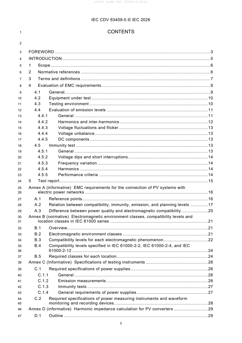
3 FOREWORD . 3
4 INTRODUCTION . 5
5 1 Scope . 6
6 2 Normative references . 6
7 3 Terms and definitions . 7
8 4 Evaluation of EMC requirements . 9
9 4.1 General . 9
10 4.2 Equipment under test . 10
11 4.3 Testing environment . 10
12 4.4 Evaluation of emission levels . 11
13 4.4.1 General . 11
14 4.4.2 Harmonics and inter-harmonics . 12
15 4.4.3 Voltage fluctuations and flicker . 13
16 4.4.4 Voltage unbalance . 13
17 4.4.5 DC components . 13
18 4.5 Immunity test . 13
19 4.5.1 General . 13
20 4.5.2 Voltage dips and short interruptions . 14
21 4.5.3 Frequency variation . 14
22 4.5.4 Harmonics . 14
23 4.5.5 Performance criteria . 14
24 5 Test report . 15
25 Annex A (informative) EMC requirements for the connection of PV systems with
26 electric power networks . 16
27 A.1 Reference points . 16
28 A.2 Relation between compatibility, immunity, emission, and planning levels . 17
29 A.3 Difference between power quality and electromagnetic compatibility . 20
30 Annex B (normative) Electromagnetic environment classes, compatibility levels and
31 location classes in IEC 61000 series . 21
32 B.1 Overview. 21
33 B.2 Electromagnetic environment classes . 21
34 B.3 Compatibility levels for each electromagnetic phenomenon . 22
35 B.4 Compatibility levels specified in IEC 61000-2-2, IEC 61000-2-4, and IEC
36 61000-2-12 . 24
37 B.5 Required classes for each location . 24
38 Annex C (Informative) Specifications of testing instruments . 26
39 C.1 Required specifications of power supplies . 26
40 C.1.1 General . 26
41 C.1.2 Emission measurements . 26
42 C.1.3 Immunity tests . 27
43 C.1.4 General requirements of power supplies . 27
44 C.2 Required specifications of power measuring instruments and waveform
45 monitoring and recording devices . 28
46 Annex D (informative) Harmonic impedance calculation for PV converters . 29
47 D.1 Outline . 29
IEC CDV 63409-5 © IEC 2026
48 D.2 Model of the inverter for harmonic assessment . 29
49 D.3 How to measure the harmonic impedance . 29
50 D.4 Multi-order approach: . 30
51 D.5 Results to be reported . 31
52 D.6 Test repetitions . 31
53 Bibliography . 32
55 Figure 1 – Overview of the IEC 63409 series . 5
56 Figure 2 – Configuration example of a PV system consisting of a single generating unit . 10
57 Figure 3 – Example of ports of PCE . 10
58 Figure 4 – Testing setup . 11
59 Figure A.1 – Three reference points where requirements are applied . 17
60 Figure A.2 – Example of the location of PCC in the public low-voltage network . 18
61 Figure A.3 – Illustration of EMC concepts . 19
62 Figure A.4 – Relation between compatibility, immunity, emission, and planning levels . 20
64 Table 1 – Performance criteria for immunity tests . 15
65 Table A.1 – Difference between power quality and electromagnetic compatibility . 20
66 Table B.1 – Classes of electromagnetic environments defined in IEC 61000-2-4 . 22
67 Table B.2 – Total harmonic distortion . 22
68 Table B.3 – Power supply voltage amplitude variations . 22
69 Table B.4 – Power supply voltage Unbalance . 22
70 Table B.5 – Power supply voltage frequency variations . 22
71 Table B.6 – Individual Harmonic voltage . 23
72 Table B.7 – Compatibility levels specified in IEC 61000-2-2/-4/-12 . 24
73 Table B.8 – Required classes for each location . 24
74 Table C.1 – Specifications of power supplies required in relevant standards . 26
75 Table C.2 – Specifications of power supplies required in relevant standards . 27
76 Table C.3 – General requirements of power supplies . 27
77 Table C.4 – Requirements for measurement instruments . 28
IEC CDV 63409-5 © IEC 2026
81 INTERNATIONAL ELECTROTECHNICAL COMMISSION
82 ____________
84 PHOTOVOLTAIC POWER GENERATING SYSTEMS CONNECTION WITH
85 THE GRID
86 – TESTING FOR POWER CONVERSION EQUIPMENT –
88 Part 5: Electromagnetic compatibility for low frequency conducted
89 disturbances
92 FOREWORD
93 1) The International Electrotechnical Commission (IEC) is a worldwide organization for standardization comprising
94 all national electrotechnical committees (IEC National Committees). The object of IEC is to promote international
95 co-operation on all questions concerning standardization in the electrical and electronic fields. To this end and
96 in addition to other activities, IEC publishes International Standards, Technical Specifications, Technical Reports,
97 Publicly Available Specifications (PAS) and Guides (hereafter referred to as “IEC Publication(s)”). Their
98 preparation is entrusted to technical committees; any IEC National Committee interested in the subject dealt with
99 may participate in this preparatory work. International, governmental and non-governmental organizations liaising
100 with the IEC also participate in this preparation. IEC collaborates closely with the International Organization for
101 Standardization (ISO) in accordance with conditions determined by agreement between the two organizations.
102 2) The formal decisions or agreements of IEC on technical matters express, as nearly as possible, an international
103 consensus of opinion on the relevant subjects since each technical committee has representation from all
104 interested IEC National Committees.
105 3) IEC Publications have the form of recommendations for international use and are accepted by IEC National
106 Committees in that sense. While all reasonable efforts are made to ensure that the technical content of IEC
107 Publications is accurate, IEC cannot be held responsible for the way in which they are used or for any
108 misinterpretation by any end user.
109 4) In order to promote international uniformity, IEC National Committees undertake to apply IEC Publications
110 transparently to the maximum extent possible in their national and regional publications. Any divergence between
111 any IEC Publication and the corresponding national or regional publication shall be clearly indicated in the latter.
112 5) IEC itself does not provide any attestation of conformity. Independent certification bodies provide conformity
113 assessment services and, in some areas, access to IEC marks of conformity. IEC is not responsible for any
114 services carried out by independent certification bodies.
115 6) All users should ensure that they have the latest edition of this publication.
116 7) No liability shall attach to IEC or its directors, employees, servants or agents including individual experts and
117 members of its technical committees and IEC National Committees for any personal injury, property damage or
118 other damage of any nature whatsoever, whether direct or indirect, or for costs (including legal fees) and
119 expenses arising out of the publication, use of, or reliance upon, this IEC Publication or any other IEC
120 Publications.
121 8) Attention is drawn to the Normative references cited in this publication. Use of the referenced publications is
122 indispensable for the correct application of this publication.
123 9) Attention is drawn to the possibility that some of the elements of this IEC Publication may be the subject of patent
124 rights. IEC shall not be held responsible for identifying any or all such patent rights.
125 IEC 63409-5 has been prepared by subcommittee TC82: Solar photovoltaic energy systems. It
126 is an International Standard.
127 The text of this International Standard is based on the following documents:
Draft Report on voting
XX/XX/FDIS XX/XX/RVD
129 Full information on the voting for its approval can be found in the report on voting indicated in
130 the above table.
131 The language used for the development of this International Standard is English.
IEC CDV 63409-5 © IEC 2026
132 This document was drafted in accordance with ISO/IEC Directives, Part 2, and developed in
133 accordance with ISO/IEC Directives, Part 1 and ISO/IEC Directives, IEC Supplement, available
134 at https://www.iec.ch/members_experts/refdocs. The main document types developed by IEC
135 are described in greater detail at https://www.iec.ch/standardsdev/publications.
136 The committee has decided that the contents of this document will remain unchanged until the
137 stability date indicated on the IEC website under webstore.iec.ch in the data related to the
138 specific document. At this date, the document will be
139 • reconfirmed,
140 • withdrawn,
141 • replaced by a revised edition, or
142 • amended.
IEC CDV 63409-5 © IEC 2026
144 INTRODUCTION
145 Power conversion equipment (PCE) is indispensable for Photovoltaic (PV) power systems in
146 order to feed the AC power energy into the grid with conversion of solar power into electricity.
147 Therefore, manufacturers of PCE ensure the performance and reliability of PCE. The
148 electromagnetic compatibility (EMC) are important aspects for the preservation of the stability,
149 reliability and efficiency of the grid and must be ensured so that PCE can avoid causing
150 interference.
151 IEC 62920 has already existed as an international standard which specifies EMC requirements
152 for PCE for use in PV power systems. However, IEC 62920 specifies EMC requirements
153 relevant to protection of radio communications and emission and immunity levels with respect
154 to high frequency electromagnetic phenomena, which are not relevant to the stability, reliability,
155 and efficiency of the grid.
156 The following figure shows the structure of the IEC 63409 series and the relationships among
157 the seven parts in the IEC 63409 series. This document proposes Part 5 of this series, which
158 outlines the conditions and procedures for evaluating electromagnetic compatibility (EMC)
159 requirements related to low frequency conducted disturbances in the connection of PCE with
160 the grid. Furthermore, the document describes the classification of environments and locations
161 where PCE is connected so that required emission and immunity levels for the stability,
162 reliability and efficiency of the grid can be clarified.
164 Figure 1 – Overview of the IEC 63409 series
IEC CDV 63409-5 © IEC 2026
168 PHOTOVOLTAIC POWER GENERATING SYSTEMS CONNECTION WITH
169 THE GRID
170 – TESTING FOR POWER CONVERSION EQUIPMENT –
172 Part 5: Electromagnetic compatibility for low frequency conducted
173 disturbances
174 1 Scope
175 This part of the IEC 63409 series specifies the conditions and procedures for evaluating
176 electromagnetic compatibility (EMC) requirements related to low frequency conducted
177 disturbances associated with the grid connection of power conversion equipment (PCE) used
178 in photovoltaic power systems, with or without electrical energy storage devices.
179 This document covers the PCE used in grid-tied PV systems which are connected to a public
180 low and medium voltage AC electric power networks or other low and medium voltage AC
181 installations. The PCE is also referred to as a grid-connected power converter (GCPC).
182 This document addresses the following low frequency conducted electromagnetic phenomena
183 as the EMC requirements:
184 – harmonics and inter-harmonics,
185 – voltage fluctuations and flicker,
186 – voltage unbalance,
187 – frequency variation
188 – DC components.
189 This document does not cover high frequency electromagnetic phenomena related to the EMC
190 requirements for the protection of radio communications, which are specified in IEC 62920.
191 This document specifies requirements for the evaluation of the following emission levels:
192 • Harmonics and inter-harmonics,
193 • Voltage fluctuations and flicker,
194 • Voltage unbalance,
195 • DC components.
196 In addition, this document specifies the following immunity tests for the PCE:
197 • Voltage dips and short interruptions,
198 • Frequency variation,
199 • Harmonics.
200 2 Normative references
201 The following documents are referred to in the text in such a way that some or all of their content
202 constitutes requirements of this document. For dated references, only the edition cited applies.
203 For undated references, the latest edition of the referenced document (including any
204 amendments) applies.
205 IEC 61000-2-2:2018, Electromagnetic compatibility (EMC) - Environment - Compatibility levels
206 for low-frequency conducted disturbances and signalling in public low-voltage power supply
207 systems
IEC CDV 63409-5 © IEC 2026
208 IEC 61000-2-4:2024, Electromagnetic compatibility (EMC) - Part 2-4: Environment -
209 Compatibility levels in power distribution systems in industrial locations for low-frequency
210 conducted disturbances
211 IEC 61000-3-2:2020, Electromagnetic compatibility (EMC) – Part 3-3: Limits – Limitation of
212 voltage changes, voltage fluctuations and flicker in public low-voltage supply systems, for
213 equipment with rated current ≤ 16 A per phase and not subject to conditional connection
214 IEC 61000-3-12:2021, Electromagnetic compatibility (EMC) - Part 3-12: Limits - Limits for
215 harmonic currents produced by equipment connected to public low-voltage systems with input
216 current >16 A and ≤ 75 A per phase
217 IEC 61000-3-3:2020, Electromagnetic compatibility (EMC) - Part 3-3: Limits - Limitation of
218 voltage changes, voltage fluctuations and flicker in public low-voltage supply systems, for
219 equipment with rated current ≤16 A per phase and not subject to conditional connection
220 IEC 61000-4-13:2015, Electromagnetic compatibility (EMC) - Part 4-13: Testing and
221 measurement techniques - Harmonics and interharmonics including mains signalling at a.c.
222 power port, low frequency immunity tests
223 IEC 61000-4-28: 2009, Electromagnetic compatibility (EMC) - Part 4-28: Testing and
224 measurement techniques - Variation of power frequency, immunity test for equipment with input
225 current not exceeding 16 A per phase
226 IEC 61000-4-11:2020, Electromagnetic compatibility (EMC) – Part 4-11: Testing and
227 measurement techniques – Voltage dips, short interruptions and voltage variations immunity
228 tests
229 IEC 61000-4-34:2009, Electromagnetic compatibility (EMC) – Part 4-34: Testing and
230 measurement techniques – Voltage dips, short interruptions and voltage variations immunity
231 tests for equipment with input current more than 16 A per phase
232 3 Terms and definitions
233 For the purposes of this document, the following terms and definitions apply.
234 For the purposes of this document, the terms and definitions given in IEC 62934, IEC TS 62786
235 series, and the following apply.
236 ISO and IEC maintain terminology databases for use in standardization at the following
237 addresses:
238 • IEC Electropedia: available at https://www.electropedia.org/
239 • ISO Online browsing platform: available at https://www.iso.org/obp
240 3.1
241 photovoltaic power generating system
242 PV system
243 electric power generating system which uses the photovoltaic effect to convert solar power into
244 electricity
245 3.2
246 power conversion equipment
247 PCE
248 electrical device converting one form of electrical power to another with respect to voltage,
249 current, frequency, phase and the number of phases
IEC CDV 63409-5 © IEC 2026
250 [SOURCE: IEC 62109-1:2010, 3.66, modified – The definition has been rephrased, and the note
251 has been deleted.]
252 3.3
253 Point of connection
254 POC
255 reference point on the electric power network where the user’s electrical facility is connected
256 [SOURCE: IEC 60050-617:2009, 617-04-01]
257 3.4
258 point of common coupling
259 PCC
260 point in an electric power system, electrically nearest to a particular load or the point of
261 connection (POC)of a power plant, at which other loads/power plants are, or may be, connected
262 Note 1 to entry: These loads can be either devices, equipment or systems, or distinct customer's installations.
263 [SOURCE: IEC 62934:2021, 3.1.11]
264 3.5
265 In-plant point of coupling
266 IPC
267 point inside a non-public power distribution system, electrically nearest to a given load or a
268 power plant, at which loads or power plants from other branches are, or could be, connected
269 Note 1 to entry: The IPC is usually the point for which electromagnetic compatibility in industrial networks is to be
270 considered.
271 [SOURCE: IEC 61000-2-4:2024, 3.1.10, modified – The definition has been rephrased]
272 3.6
273 power distribution systems in industrial locations
274 industrial power distribution system
275 distribution network which is separated by at least one separation transformer from the public
276 power supply system to which other customer installations are connected
277 3.7
278 planning level
279 a level of a particular disturbance in a particular environment, adopted as a reference value for
280 the limits to be set for the emissions from large loads and installations, in order to co-ordinate
281 those limits with all the limits adopted for equipment intended to be connected to the power
282 supply system
283 NOTE The planning level is locally specific and is adopted by those responsible for planning and operating the power
284 supply network in the relevant area. For further information, see Annex A of IEC 61000-2-2
285 [SOURCE: IEC 61000-2-2:2018]
286 3.8
287 port
288 particular interface of an equipment which couples this equipment with the external
289 electromagnetic environment and through which the equipment is influenced by this
290 environment
291 [SOURCE: IEC 60050-161:2014, 161-01-27]
IEC CDV 63409-5 © IEC 2026
292 3.9
293 electromagnetic environment
294 totality of electromagnetic phenomena existing at a given location
295 [SOURCE: IEC 60050-161:2018, 161-01-01, modified - Note 1 to entry is deleted]
296 3.10
297 signal and control port
298 port intended for the interconnection of components of PCE, or between PCE and local auxiliary
299 equipment, and used in accordance with relevant functional specifications
300 Note 1 to entry: Examples include RS-232, Universal Serial Bus (USB), High-Definition Multimedia Interface (HDMI),
301 436 IEEE standard 1394 (“Fire Wire”) and control pilot.
302 [SOURCE: CISPR 32:2019, 3.1.30, modified]
303 3.11
304 wired network port
305 port for the connection of voice, data and signalling transfers intended to interconnect widely-
306 dispersed systems by direct connection to a single-user or multi-user communication network
307 Note 1 to entry: Examples of these include CATV, PSTN, ISDN, xDSL, LAN and similar networks.
308 Note 2 to entry: These ports may support screened or unscreened cables and may also carry AC or DC power where
309 this is an integral part of the telecommunication specification.
310 [SOURCE: CISPR 32:2019, 3.1.32]
311 3.12
312 agreed power
313 value of the apparent power of the disturbing installation on which the customer and the system
314 operator or owner agree. In the case of several points of connection, a different value may be
315 defined for each connection point
316 [SOURCE: IEC TR 61000-3-6, 3.1]
317 4 Evaluation of EMC requirements
318 4.1 General
319 Figure 2 illustrates an example of the configuration of a grid-tied PV system, which consists of
320 a single PCE. As Annex A describes, the electromagnetic compatibility requirements shall be
321 applied at the point of common connection (PCC) or the in-plant point coupling ‘(IPC) in a
322 electric power network. To ensure that the disturbance level at the point of connection (POC)
323 of the PV system does not exceed limits, which are apportioned based on the planning level,
324 the evaluation of emission levels at POC of the PV system or AC power ports of PCE comprising
325 the PV system are required. Along with this, PCE is required to have immunity at least at the
326 compatibility level.
IEC CDV 63409-5 © IEC 2026
328 Figure 2 – Configuration example of a PV system consisting of a single generating unit
329 4.2 Equipment under test
330 When the PCE is subject to the evaluation of EMC requirements, the evaluation shall be
331 implemented in manufacture’s facilities and/or in testing premises using appropriate DC power
332 supplies for testing, instead of connecting solar photovoltaic modules or electrical storage
333 devices to the PCE.
334 Figure 3 shows an example of ports of PCE. The DC and AC power supplies shall be connected
335 to the DC power ports and the AC power ports. Auxiliary power ports, if any, and if necessary
336 to operate the PCE as intended, shall be connected to the appropriate power supplies during
337 testing.
338 The signal and control port is a port intended for the interconnection of components of the PCE,
339 or between the PCE and local auxiliary equipment, and used in accordance with relevant
340 functional specifications. The wired network port is a port for the connection of voice, data and
341 signalling transfers intended to interconnect widely dispersed systems by direct connection to
342 a single-user or multi-user communication network. These ports, other than power ports, shall
343 be interconnected to any associated equipment and systems to ensure that all relevant
344 functions for these ports are in operation as intended.
346 Figure 3 – Example of ports of PCE
347 4.3 Testing environment
348 Emission measurements and immunity tests for the PCE shall be performed in accordance with
349 a testing setup as shown in Figure 4. Voltage, current, frequency, active power, reactive power,
350 and apparent power at the AC power port shall be measured for the evaluation of EMC
351 requirements.
352 The PCE shall be set up within its actual installation condition during the evaluation of emission
353 and immunity requirements. Connection of cables shall follow installation manuals to be applied.
IEC CDV 63409-5 © IEC 2026
354 AC power ports of PCE shall be connected to the AC power supplies. Certain impedance should
355 be added between the PCE and the AC power supplies, by following testing requirements which
356 are describe in 4.4 for the evaluation of emission levels and 4.5 for the immunity test in detail.
357 Appropriate AC power supplies shall be used so that continuous and stable AC voltage and
358 frequency for the PCE can be supplied during the evaluation. Additionally, the AC power
359 supplies shall be designed to prevent any electromagnetic disturbances generated by the AC
360 power supplies from affecting the evaluation results.
361 DC power ports of PCE shall be connected to the DC power supplies. Where the PCE is
362 equipped with more than one DC power port, each independent DC power ports shall be
363 connected to an individual DC power supply for testing.
364 The DC power supplies shall deliver continuous and stable DC voltage, current and power
365 during the evaluation. Furthermore, the DC power supplies shall be designed to ensure that
366 electromagnetic disturbances generated by DC power supplies do not influence the evaluation
367 results.
368 Power measuring instruments and waveform monitoring and recording devices shall be
369 connected to AC and DC power ports respectively.
372 Figure 4 – Testing setup
373 Required specifications of power supplies are specified in C.1. General requirements of power
374 supplies are given in C.1.4 and Table C.3.
375 Required specifications of power measuring instruments and waveform monitoring and
376 recording devices are specified in C.2.
377 4.4 Evaluation of emission levels
378 4.4.1 General
379 The evaluation of emission levels of the following four low frequency conducted electromagnetic
380 phenomena shall be carried out:
381 • Harmonics and inter-harmonics
382 • Voltage fluctuations and flicker
383 • Voltage unbalance
384 • DC components
IEC CDV 63409-5 © IEC 2026
385 The following three stages of evaluation of emission levels are defined in IEC TR 61000-3-14,
386 which applies to installations connected to low voltage public power systems. Similarly, IEC TR
387 61000-3-6, IEC TR 61000-3-7, and IEC TR 61000-3-13 define evaluation stages for installations
388 connected to medium voltage public power systems. These stages may be used in sequence
389 or independently. In this document, only the stage 1 is applied.
390 • Stage 1: evaluation of emission levels of PCE
391 • Stage 2: evaluation of emission levels at POC
392 • Stage 3: evaluation of emission levels under special conditions
393 IEC TR 61000-2-6 provides the procedures to evaluate emission levels of equipment and
394 installations which are connected to low and medium voltage non-public power systems.
395 The emission levels shall be evaluated under the operating mode in which the PCE feeds 25 %,
396 50 % and 100 % of rated power at the AC power ports. Tolerance of power shall be within 5 %
397 of rated power.
398 4.4.1.1 Stage 1: evaluation of emission levels of PCE
399 If agreed power of a PV system is small relative to the short circuit capacity at the POC of the
400 PV system, it should not be necessary to carry out detailed evaluation of emission levels at the
401 POC. Then, the evaluation of emission levels shall be applied to the PCE.
402 4.4.1.2 Stage 2: evaluation of emission levels at POC
403 If agreed power of a PV system is not small relative to the short circuit capacity at the POC of
404 the PV system, it should be necessary to carry out detailed evaluation of emission levels at the
405 POC.
406 4.4.1.3 Stage 3: evaluation of emission levels under special conditions
407 Under some circumstances, emission levels may be required beyond the limits allowed in stage
408 2. In such a situation, a careful study of the connection of the PV system should be carried out,
409 taking account of characteristics of the actual electric power networks and the pre-existing
410 levels of disturbances.
411 4.4.2 Harmonics and inter-harmonics
412 When PCE is intended to be connected to a public low voltage power network, and its rated
413 current at AC power ports is up to 16 A per phase, harmonic current measurement specified in
414 Clause 6 of IEC 61000-3-2 shall be applied.
415 When PCE is intended to be connected to a public low voltage power network, and its rated
416 current at AC power ports is exceeding 16 A and up to and including 75 A per phase, harmonic
417 current measurement specified in Clause 4 and Clause 7 of IEC 61000-3-12 shall be applied.
418 The measurement method to be used for harmonic and inter-harmonic measurements is the
419 class A method specified in IEC 61000-4-30. The general guide on harmonics and inter-
420 harmonics measurements and instrumentation are defined in IEC 61000-4-7.
421 For PCE which is not covered by IEC 61000-3-2 and IEC 61000-3-12 or exceeding 75 A per
422 phase, 7.2 of IEC TR 61000-3-14 can be applied for the evaluation of emission levels at the
423 POC of PV systems, which is connected to public low voltage power networks.
424 For PV systems connected to medium voltage public networks, IEC TR 61000-3-6 can be
425 applied. Information on harmonic impedance is a prerequisite in order to assess the emission
426 levels of the considered installation. Harmonic impedance calculation for PV converters is
427 described in Annex D.
IEC CDV 63409-5 © IEC 2026
428 4.4.3 Voltage fluctuations and flicker
429 When PCE is intended to be connected to a public low voltage power network, and its rated
430 current at AC power ports is up to 16 A per phase, voltage fluctuations and flicker
431 measurements specified in Clause 6 of IEC 61000-3-3 shall be applied.
432 When PCE is intended to be connected to a public low voltage power network, and its rated
433 current at AC power ports is exceeding 16 A and up to and including 75 A per phase, voltage
434 fluctuations and flicker measurements specified in Clause 6 of IEC 61000-3-11 shall be applied.
435 When PCE is intended to be connected to a public low voltage power network, and its rated
436 current at AC power ports is exceeding 75 A per phase, voltage fluctuations and flicker
437 measurements shall be applied with the actual system impedance. For further information, see
438 IEC TS 61000-3-5.
439 For PCE which is not covered by IEC 61000-3-3 and IEC 61000-3-11 or exceeding 75 A per
440 phase, 8.2 of IEC TR 61000-3-14 can be applied for the evaluation of emission levels at the
441 POC of PV systems, which is connected to public low voltage power networks.
442 For PV systems connected to medium voltage public networks, IEC TR 61000-3-7 can be
443 applied.
444 IEC 61000-4-15 specifies how to measure for P (long-term flicker severity). P (long-term
st lt
445 flicker severity), d (maximum absolute voltage change) and d (maximum steady state
max c
446 voltage change) and provides detailed specifications for the evaluation of these directly
447 measured parameters.
448 4.4.4 Voltage unbalance
449 The evaluation of voltage unbalance only applies to three phase systems.
450 For a PV system which fulfil a criterion that the single-phase power is less than or equal to
451 0,2 % of the short circuit power at the POC, PCE comprising the PV system can be connected
452 to the low voltage public power network without further examination.
453 For a PV system which does not fulfil the criterion, 9.2 of IEC TR 61000-3-14 can be applied
454 for the evaluation of voltage unbalance levels at the POC of PV systems.
455 For PV systems connected to medium voltage public networks, IEC TR 61000-3-13 can be
456 applied.
457 Clause 5.7 of IEC 61000-4-30 specifies how to measure the negative sequence unbalance ratio
458 as voltage unbalance.
459 4.4.5 DC components
460 The zero-sequence component of voltage at the AC power ports of the PCE shall be evaluated
461 according to Clause 5.7 of IEC 61000-4-30.
462 4.5 Immunity test
463 4.5.1 General
464 The PCE is required to have immunity at least at the compatibility level provided in Annex B.
465 The following immunity tests shall be carried out:
466 • Voltage dips and short interruptions
467 • Frequency variation
IEC CDV 63409-5 © IEC 2026
468 • Harmonics
469 The level of immunity tests shall be determined in accordance with required classes of locations
470 where the PCE is installed. Required classes for locations are provided in Annex B.
471 For PCEs installed in residential, commercial, or light industrial locations, immunity level class
472 2 shall be applied, whereas immunity level class 3 shall be applied for PCEs installed in
473 industrial locations.
474 The immunity test shall be carried out within the intended operating range specified for intended
475 use. The intended use may include control signals, wired and wireless communication.
476 During testing, it is recommended that the PCE is operated at the rated power at AC power
477 ports. If the maximum feeding power is not technically available due to the restriction of power
478 capacity of test equipment in the laboratory, it may be necessary to conduct some preliminary
479 testing to adjust voltage and current levels at the AC power ports and the feeding power of the
480 PCE, and the voltage, current and power shall be recorded in the test report.
481 4.5.2 Voltage dips and short interruptions
482 IEC 61000-4-11 shall apply to PCE below 16 A, and IEC 61000-4-34 shall be for PCE with
483 current levels above 16 A per phase.
484 4.5.3 Frequency variation
485 Frequency variation immunity test shall be applied in accordance with IEC 61000-4-28. When
486 the test environment can be available for PCE with rated current above 16 A, the PCE can be
487 tested according to IEC 61000-4-28.
488 4.5.4 Harmonics
489 Harmonics immunity test shall be applied in accordance with IEC 61000-4-13. When the test
490 environment can be available for PCE with rated current above 16 A, the PCE can be tested
491 according to IEC 61000-4-13.
492 Note Immunity level class 2 is approximately 1,5 times the compatibility level class 2 of Individual Harmonic voltage
493 listed in Annex B, whereas immunity level class 2 is approximately 1,5 times the compatibility level class 3.
494 4.5.5 Performance criteria
495 The performance criteria for the immunity tests are given in Table 1. A precise description and
496 definition of performance criterion shall be noted in the test report based on the intended use
497 and the following criteria. Only the performance criteria specified in this standard apply.
IEC CDV 63409-5 © IEC 2026
498 Table 1 – Performance criteria for immunity tests
Item Criterion A Criterion B Criterion C
Operating status No noticeable change of Noticeable changes of the Shutdown, changes in
the operating status. operating characteristic. operating status.
Operating as intended. Self-recoverable Triggering of protective
devices.
Not self-recoverable
Power output Power output permitted to Power output permitted to Loss of power output.
vary only within ±25 %. temporarily vary outside
Not self-recoverable
±25 %
Self-recoverable
External and internal No noticeable change of Changes only during test Shutdown, triggering of
indications and metering the operating status. protective devices.
Not self-recoverable
499 5 Test report
500 The test report shall contain all the information necessary to reproduce the test. In particular,
501 the following shall be recorded:
502 – the testing items specified in a test plan;
503 – identification of the EUT and any associated equipment, e.g. brand name, product type,
504 serial number;
505 – identification of the test equipment, e.g. brand name, product type, serial number;
506 – any special environmental conditions in which the test was performed, e.g. shielded room;
507 – any specific conditions of use, for example cable length or type, shielding or grounding, or
508 operating conditions of PCE.
509 – any specific conditions necessary to enable the test to be performed.
510 The following shall be recorded in the test report for immunity tests:
511 – performance level defined by the manufacturer, requestor or purchaser;
512 – performance criterion according to test results;
513 – any effects on the PCE observed during or after the application of the test disturbance, and
514 the duration for which these effects persist;
515 – the rationale for the pass/fail decision (based on the performance criterion agreed between
516 the manufacturer and the purchaser).
IEC CDV 63409-5 © IEC 2026
517 Annex A
518 (informative)
520 EMC requirements for the connection of PV systems with electric power
521 networks
522 A.1 Reference points
523 Basic requirements for the connection of the PV system with the electric power network, or the
524 grid, are to:
...