

oSIST prEN 81-72:2026
(Main)Safety rules for the construction and installation of lifts - Particular applications for passenger and goods passenger lifts - Part 72: Firefighters lifts
- Abstract
1.1 This document specifies the additional requirements to EN ISO 8100-1:2026 for new passenger and goods passenger lifts, which can be used to support firefighting and rescue under firefighters control.
1.2 This document does not apply to:
- lifts for evacuation due to circumstances which introduce other hazards such as explosion threat, chemical or biological attack, flooding, storm damage, or earthquake. In these cases, this document can be used as a basis with further measures as required from risk assessment;
- the provision of evacuation aids to assist when the evacuation lift is unavailable;
- lifts with partially enclosed wells;
- lifts installed in new or existing buildings, which are not included in fire resisting building structure.
1.3 This document does not define the use of other than the highest deck of a multi deck lift for firefighting operations.
1.4 The significant hazards covered by this document are listed in Annex H.
1.5 The following significant hazards are out of the scope of this document:
- fire or smoke in the firefighters lift well, safe areas, machinery spaces or car;
- ingress of water to the lift well during firefighting operations;
- insufficient or incorrectly located firefighters lifts;
- insufficient firefighters lift capacity;
- inability of users to understand the use of the lift in firefighting operations;
- entrapment in waiting area (safe area) due to absence of lift service or adjacent stairs;
- structural collapse or failure of building services (including public supply network, lighting, ventilation) before the firefighting using lifts has been completed;
- presence of harmful gases, potentially explosive atmosphere, extreme climate conditions, transport of dangerous goods;
- unavailability of the firefighters lift.
This document is not applicable to firefighters lifts manufactured before the date of its publication.
- Status
- Not Published
- Public Enquiry End Date
- 30-Oct-2026
- Technical Committee
- DTN - Lift and transport appliances
- Current Stage
- 4020 - Public enquire (PE) (Adopted Project)
- Start Date
- 17-Aug-2026
- Due Date
- 04-Jan-2027


oSIST prEN 81-72:2026 is the Slovenian adoption of the CEN draft European Standard prEN 81-72:2026, published by SIST. It specifies additional safety rules to EN ISO 8100-1:2026 for new passenger and goods passenger lifts that can be used under firefighters control to support firefighting and rescue. It is written for lift manufacturers, installers, designers, building teams, inspectors, maintenance providers, and fire and rescue service stakeholders.
What does oSIST prEN 81-72:2026 specify?
oSIST prEN 81-72:2026 sets extra requirements for firefighters lifts, including the car, doors, controls, water protection, rescue means, communication, maintenance information, and the building conditions needed around the lift. Clause 4 contains the technical requirements, Clause 5 gives the verification approach, Clause 6 covers information for use, and Clause 7 covers the building interface.
The scope is limited to new passenger and goods passenger lifts used to support firefighting and rescue under firefighters control. It excludes evacuation lifts for special hazards such as explosion threat, chemical or biological attack, flooding, storm damage, or earthquake, as well as partially enclosed wells and lifts in buildings that are not part of a fire resisting building structure. It also limits firefighting operations to the highest deck of a multi deck lift.
| Annex | What it covers |
|---|---|
| A | Example of a firefighting lift concept |
| B | Basic layouts for firefighters lift |
| C | Water protection in the lift well |
| D | Pictogram for a firefighters lift |
| E | Examples of self-rescue procedures for firefighters |
| F | Information on the building-related conditions in which the lift is installed |
| G | Maintenance guidance |
| H | List of significant hazards |
| ZA | Relationship with Directive 2014/33/EU |
What are the key requirements of oSIST prEN 81-72:2026?
Design basis and performance
Clause 4.3 requires firefighters lifts to be built on EN ISO 8100-1:2026 and to add the protection, controls and signals needed for fire service use. In practice, this means the lift is not a separate concept from a normal passenger lift, but a reinforced version with specific fire service functions.
The same clause sets the main car dimensions, minimum rated load, clear entrance width, and, where needed, stretcher or bed dimensions. It also requires the lift to reach the highest landing served in firefighting operations from the fire service access level within a set time, using 80% of rated load. For a buyer or designer, this is a key sizing and performance check.
Water, temperature and electrical protection
Clause 4.4 and Annex C focus on water exposure. Electrical equipment in the well, on the car roof, and around the car sides needs IPX3 or IPX1 protection depending on location, and equipment close to the pit floor needs IP67. Machinery-space equipment outside the well must be protected against malfunction caused by water, and the car roof must not allow water to accumulate.
Clause 4.3.5 also requires the lift to keep working in high-temperature and smoke-related conditions, and Clause 4.7.5 requires the firefighters lift to remain independent from other lifts in the same group. In practice, this means the design must tolerate a fire-fighting environment and not fail because another lift or wet equipment has a fault.
Rescue means and self-rescue
Clause 4.5 requires an emergency trap door in the car roof, ladders or stepping points for reaching the roof, and instructions for self-rescue in the car. The emergency trap door must be usable for rescue without blocking access, and its operation must stop the lift from being used until it is reset correctly.
This matters because trapped firefighters may need to leave the car without outside recovery. Annex E shows example self-rescue procedures, including climbing from the car to the roof and then to the next landing.
Doors, controls and firefighting operation
Clause 4.6 requires horizontally sliding automatic power-operated mechanically coupled car and landing doors. Clause 4.7 then defines the firefighters lift switch, its location and marking, and the two operating phases. Phase 1 recalls the lift to the fire service access level and disables normal calls; Phase 2 gives control entirely to firefighters car controls.
The same clause protects safety functions: the firefighters lift switch must not override electric safety devices, inspection operation, emergency electrical operation, seismic mode, remote alarm systems, or maintenance control. For dual entry cars, extra rules govern which door may open and which controls remain active, so firefighters can use the correct side safely.
Power recovery, indicators and communication
Clause 4.8 requires the lift to return to service within 1 minute after power is restored, and if it must move to establish its position, it may move only one floor towards the fire service access level. Clause 4.9 covers indicators, control placement and enclosure protection, while Clause 4.10 requires a two-way speech communication system between the car and the fire service access level, plus the machinery space where emergency devices are located.
In practice, these clauses make the lift easier to use during an emergency and easier to re-enter service afterward. They also support operational communication when firefighters are managing the lift under difficult conditions.
Building interface and documentation
Clause 7 and Annex F require the building-related boundary conditions to be defined and included in the installation plans and instructions. This includes fire resistance, safe areas, water management, power supply, escape routes, signage, and access to the machinery space. For project teams, this means the lift cannot be specified correctly without coordinating the building layout and fire strategy.
What terms does oSIST prEN 81-72:2026 define?
- Control system - the lift system that takes input signals and generates output signals so the equipment operates as intended.
- Firefighters lift - a lift with protection, controls and signals that allow exclusive control by firefighters.
- Firefighters lift switch - the switch used to start firefighters service.
- Fire service access level (FSAL) - the entry level intended for firefighters to access the lift.
- Safe area - a fire and smoke protected area at the landing in front of the lift.
- Dual entry car - a car with two car doors.
Who uses oSIST prEN 81-72:2026?
Lift manufacturers and installers use oSIST prEN 81-72:2026 to design the car, controls, communication system, water protection and rescue features. Building designers and fire strategy teams use it to coordinate safe areas, access routes, fire resistance and power supply. Inspectors, maintenance providers and regulators use it to verify that the lift behaves correctly in firefighting mode and that the building conditions support its use.
What changed in oSIST prEN 81-72:2026 from the previous edition?
oSIST prEN 81-72:2026 supersedes EN 81-72:2020. The changes listed in the foreword are the deletion of assumptions from the introduction, clarified and streamlined requirements, removal of the former annex on secondary power supplies, removal of the former annex on water protection in the lift well, removal of the former annex on water management, addition of normative Annex F on building-related conditions, movement of the significant hazards list to informative Annex H, and updating of Annex ZA.
Which standards are used with oSIST prEN 81-72:2026?
The document refers to EN ISO 8100-1:2026 for the base lift safety rules, EN ISO 12100:2010 for risk assessment and risk reduction, EN 60529:1991 for IP enclosure ratings, EN 81-70:2021+A1:2022 for accessibility-related control and indicator placement, and EN 131-1:2015+A2:2025 and EN 131-2:2010+A3:2025 for ladder terms, sizes, testing and marking. It also names EN 131-6:2019+A1:2025 for telescopic ladders, EN 12101-13:2022 for pressure differential systems, and EN 81-58:2026 for landing-door fire resistance in the building interface.
What does the oSIST prEN 81-72:2026 document contain?
oSIST prEN 81-72:2026 contains a verification table in Clause 5 that links each requirement to visual inspection, design checks, measurements and functional tests. It also contains figures and example layouts in Annexes A, B, C and E for firefighting concepts, typical building arrangements, water protection and self-rescue. Annex D gives the firefighters lift pictogram, Annex F sets the building-related information to be supplied, and Annex H lists the significant hazards addressed by the document.
Relations
- Effective Date
- 25-Jun-2025
Get Certified
Connect with accredited certification bodies for this standard

DIBt (Deutsches Institut für Bautechnik)
German Institute for Building Technology.
DIN CERTCO
DIN Group product certification.

Kiwa BDA Testing
Building and construction product certification.
Sponsored listings
Frequently Asked Questions
oSIST prEN 81-72:2026 is a draft published by the Slovenian Institute for Standardization (SIST). Its full title is "Safety rules for the construction and installation of lifts - Particular applications for passenger and goods passenger lifts - Part 72: Firefighters lifts". This standard covers: 1.1 This document specifies the additional requirements to EN ISO 8100-1:2026 for new passenger and goods passenger lifts, which can be used to support firefighting and rescue under firefighters control. 1.2 This document does not apply to: - lifts for evacuation due to circumstances which introduce other hazards such as explosion threat, chemical or biological attack, flooding, storm damage, or earthquake. In these cases, this document can be used as a basis with further measures as required from risk assessment; - the provision of evacuation aids to assist when the evacuation lift is unavailable; - lifts with partially enclosed wells; - lifts installed in new or existing buildings, which are not included in fire resisting building structure. 1.3 This document does not define the use of other than the highest deck of a multi deck lift for firefighting operations. 1.4 The significant hazards covered by this document are listed in Annex H. 1.5 The following significant hazards are out of the scope of this document: - fire or smoke in the firefighters lift well, safe areas, machinery spaces or car; - ingress of water to the lift well during firefighting operations; - insufficient or incorrectly located firefighters lifts; - insufficient firefighters lift capacity; - inability of users to understand the use of the lift in firefighting operations; - entrapment in waiting area (safe area) due to absence of lift service or adjacent stairs; - structural collapse or failure of building services (including public supply network, lighting, ventilation) before the firefighting using lifts has been completed; - presence of harmful gases, potentially explosive atmosphere, extreme climate conditions, transport of dangerous goods; - unavailability of the firefighters lift. This document is not applicable to firefighters lifts manufactured before the date of its publication.
1.1 This document specifies the additional requirements to EN ISO 8100-1:2026 for new passenger and goods passenger lifts, which can be used to support firefighting and rescue under firefighters control. 1.2 This document does not apply to: - lifts for evacuation due to circumstances which introduce other hazards such as explosion threat, chemical or biological attack, flooding, storm damage, or earthquake. In these cases, this document can be used as a basis with further measures as required from risk assessment; - the provision of evacuation aids to assist when the evacuation lift is unavailable; - lifts with partially enclosed wells; - lifts installed in new or existing buildings, which are not included in fire resisting building structure. 1.3 This document does not define the use of other than the highest deck of a multi deck lift for firefighting operations. 1.4 The significant hazards covered by this document are listed in Annex H. 1.5 The following significant hazards are out of the scope of this document: - fire or smoke in the firefighters lift well, safe areas, machinery spaces or car; - ingress of water to the lift well during firefighting operations; - insufficient or incorrectly located firefighters lifts; - insufficient firefighters lift capacity; - inability of users to understand the use of the lift in firefighting operations; - entrapment in waiting area (safe area) due to absence of lift service or adjacent stairs; - structural collapse or failure of building services (including public supply network, lighting, ventilation) before the firefighting using lifts has been completed; - presence of harmful gases, potentially explosive atmosphere, extreme climate conditions, transport of dangerous goods; - unavailability of the firefighters lift. This document is not applicable to firefighters lifts manufactured before the date of its publication.
oSIST prEN 81-72:2026 is classified under the following ICS (International Classification for Standards) categories: 13.220.10 - Fire-fighting; 91.140.90 - Lifts. Escalators. The ICS classification helps identify the subject area and facilitates finding related standards.
oSIST prEN 81-72:2026 has the following relationships with other standards: It is inter standard links to SIST EN 81-72:2020. Understanding these relationships helps ensure you are using the most current and applicable version of the standard.
oSIST prEN 81-72:2026 is associated with the following European legislation: EU Directives/Regulations: 2014/33/EU; Standardization Mandates: M/599. When a standard is cited in the Official Journal of the European Union, products manufactured in conformity with it benefit from a presumption of conformity with the essential requirements of the corresponding EU directive or regulation.
oSIST prEN 81-72:2026 is available in PDF format for immediate download after purchase. The document can be added to your cart and obtained through the secure checkout process. Digital delivery ensures instant access to the complete standard document.
Standards Content (Sample)
SLOVENSKI STANDARD
01-oktober-2026
Varnostna pravila za konstruiranje in vgradnjo dvigal (liftov) - Posebne aplikacije
za osebna in osebno-tovorna dvigala - 72. del: Dvigala za gasilce
Safety rules for the construction and installation of lifts - Particular applications for
passenger and goods passenger lifts - Part 72: Firefighters lifts
Sicherheitsregeln für die Konstruktion und den Einbau von Aufzügen - Besondere
Anwendungen für Personen- und Lastenaufzüge - Teil 72: Feuerwehraufzüge
Règles de sécurité pour la construction et l'installation des élévateurs - Applications
particulières pour les ascenseurs et ascenseurs de charge - Partie 72 : Ascenseurs
pompiers
Ta slovenski standard je istoveten z: prEN 81-72
ICS:
13.220.10 Gašenje požara Fire-fighting
91.140.90 Dvigala. Tekoče stopnice Lifts. Escalators
2003-01.Slovenski inštitut za standardizacijo. Razmnoževanje celote ali delov tega standarda ni dovoljeno.
DRAFT
EUROPEAN STANDARD
NORME EUROPÉENNE
EUROPÄISCHE NORM
October 2026
ICS 91.140.90 Will supersede EN 81-72:2020
English Version
Safety rules for the construction and installation of lifts -
Particular applications for passenger and goods passenger
lifts - Part 72: Firefighters lifts
Règles de sécurité pour la construction et l'installation Sicherheitsregeln für die Konstruktion und den Einbau
des élévateurs - Applications particulières pour les von Aufzügen - Besondere Anwendungen für
ascenseurs et ascenseurs de charge - Partie 72 : Personen- und Lastenaufzüge - Teil 72:
Ascenseurs pompiers Feuerwehraufzüge
This draft European Standard is submitted to CEN members for enquiry. It has been drawn up by the Technical Committee
CEN/TC 10.
If this draft becomes a European Standard, CEN members are bound to comply with the CEN/CENELEC Internal Regulations
which stipulate the conditions for giving this European Standard the status of a national standard without any alteration.
This draft European Standard was established by CEN in three official versions (English, French, German). A version in any other
language made by translation under the responsibility of a CEN member into its own language and notified to the CEN-CENELEC
Management Centre has the same status as the official versions.
CEN members are the national standards bodies of Austria, Belgium, Bulgaria, Croatia, Cyprus, Czech Republic, Denmark, Estonia,
Finland, France, Germany, Greece, Hungary, Iceland, Ireland, Italy, Latvia, Lithuania, Luxembourg, Malta, Netherlands, Norway,
Poland, Portugal, Republic of North Macedonia, Romania, Serbia, Slovakia, Slovenia, Spain, Sweden, Switzerland, Türkiye and
United Kingdom.
Recipients of this draft are invited to submit, with their comments, notification of any relevant patent rights of which they are
aware and to provide supporting documentation.
Warning : This document is not a European Standard. It is distributed for review and comments. It is subject to change without
notice and shall not be referred to as a European Standard.
EUROPEAN COMMITTEE FOR STANDARDIZATION
COMITÉ EUROPÉEN DE NORMALISATION
EUROPÄISCHES KOMITEE FÜR NORMUNG
CEN-CENELEC Management Centre: Rue de la Science 23, B-1040 Brussels
© 2026 CEN All rights of exploitation in any form and by any means reserved Ref. No. prEN 81-72:2026 E
worldwide for CEN national Members.
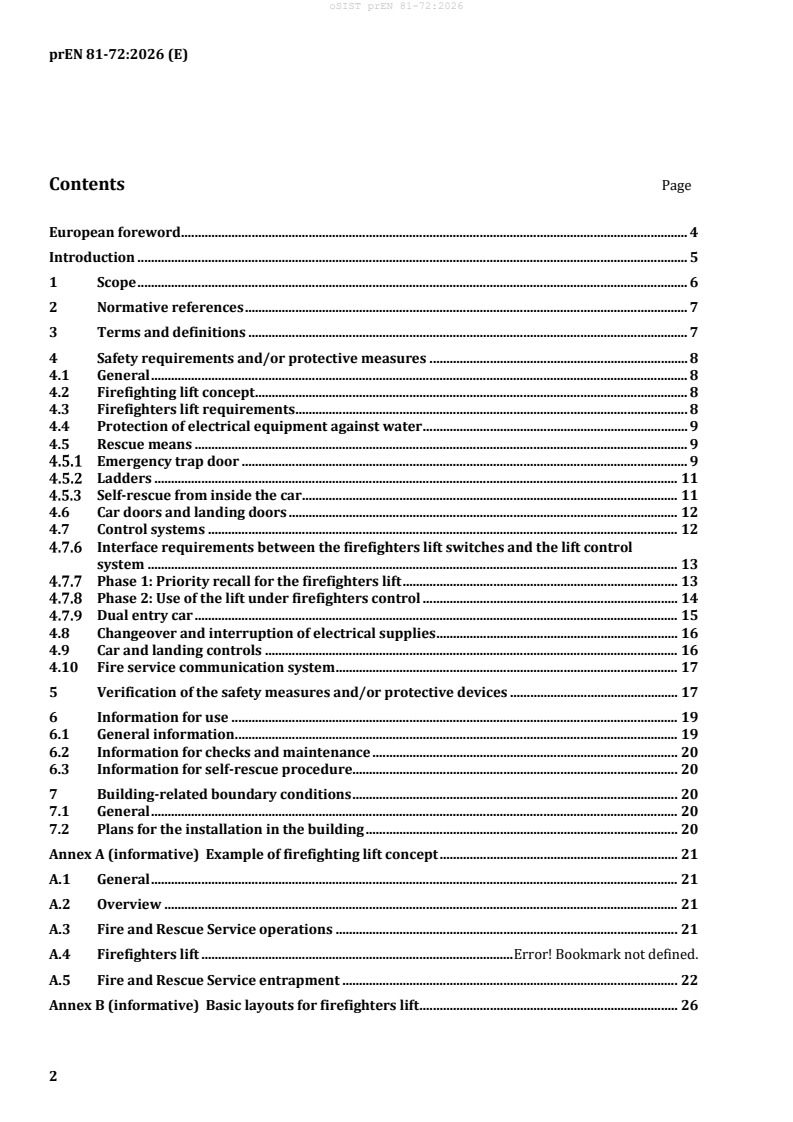
Contents Page
European foreword . 4
Introduction . 5
1 Scope . 6
2 Normative references . 7
3 Terms and definitions . 7
4 Safety requirements and/or protective measures . 8
4.1 General . 8
4.2 Firefighting lift concept . 8
4.3 Firefighters lift requirements . 8
4.4 Protection of electrical equipment against water . 9
4.5 Rescue means . 9
Emergency trap door . 9
Ladders . 11
Self-rescue from inside the car . 11
4.6 Car doors and landing doors . 12
4.7 Control systems . 12
Interface requirements between the firefighters lift switches and the lift control
system . 13
Phase 1: Priority recall for the firefighters lift . 13
Phase 2: Use of the lift under firefighters control . 14
Dual entry car . 15
4.8 Changeover and interruption of electrical supplies . 16
4.9 Car and landing controls . 16
4.10 Fire service communication system . 17
5 Verification of the safety measures and/or protective devices . 17
6 Information for use . 19
6.1 General information . 19
6.2 Information for checks and maintenance . 20
6.3 Information for self-rescue procedure. 20
7 Building-related boundary conditions . 20
7.1 General . 20
7.2 Plans for the installation in the building . 20
Annex A (informative) Example of firefighting lift concept . 21
A.1 General . 21
A.2 Overview . 21
A.3 Fire and Rescue Service operations . 21
A.4 Firefighters lift . Error! Bookmark not defined.
A.5 Fire and Rescue Service entrapment . 22
Annex B (informative) Basic layouts for firefighters lift . 26
Annex C (informative) Water protection in the lift well . 30
Annex D (normative) Pictogram for a firefighters lift . 32
Annex E (informative) Examples of self-rescue procedures for firefighters . 33
E.1 Self-rescue procedure using stepping points in the car . 33
E.2 Self-rescue procedure using ladder stored within the car . 34
Annex F (normative) Information on the building-related conditions in which the lift is
installed . 37
F.1 General . 37
F.2 Building design . 37
F.3 Firefighters lift operating environment . 37
F.4 Separation of the lift well . 38
F.5 Safe area . 38
F.6 Fire resistance of fire shutters and fire doors . 39
F.7 Emergency operation signage . 39
F.8 Water management. 39
F.9 External rescue . 40
F.10 Intermediate emergency doors . 40
F.11 Protection of electric wires and cables and hydraulic hoses . 40
F.12 Power supply for the firefighters lift . 40
F.13 Air pressurization of the lift well . 41
F.14 Noise . 41
Annex G (informative) Maintenance guidance . 42
Annex H (informative) List of significant hazards . 43
Annex ZA (informative) Relationship between this European Standard and the essential
requirements of Directive 2014/33/EU aimed to be covered . 45
Bibliography . 47
European foreword
This document (prEN 81-72:2026) has been prepared by Technical Committee CEN/TC 10 “Lifts,
escalators and moving walks”, the secretariat of which is held by AFNOR.
This document is currently submitted to the CEN Enquiry.
This document supersedes EN 81-72:2020.
The main changes are as follows:
— the assumptions have been deleted from the introduction;
— requirements have been clarified and streamlined;
— informative Annex C (Power supplies for firefighters lifts — Secondary power supplies) has been
removed;
— normative Annex D (Water protection in the lift well) has been removed;
— informative Annex E (Water management) has been removed;
— normative Annex F (Information on the building-related conditions in which the lift is installed) has
been added;
— Clause 4 (List of significant hazards) moved to informative Annex H;
— the Annex ZA has been updated.
This document is part of the EN 81 series of standards. The structure of the EN 81 series of standards is
described in CEN/TR 81-10:2008.
This document has been prepared under a standardization request addressed to CEN by the European
Commission. The Standing Committee of the EFTA States subsequently approves these requests for its
Member States.
For the relationship with EU Legislation, see informative Annex ZA, which is an integral part of this
document.
Introduction
This document is a type C standard as stated in EN ISO 12100:2010.
This document is of relevance, in particular for the following stakeholder groups representing the market
players with regard to machinery safety:
— machine manufacturers (small, medium and large enterprises);
— health and safety bodies (regulators, accident prevention organizations, market surveillance, etc.).
Others can be affected by the level of machinery safety achieved with the means of the document by the
above-mentioned stakeholder groups:
— machine users/employers (small, medium and large enterprises);
— machine users/employees (e.g. trade unions, organizations for persons with special needs);
— service providers, e.g. for maintenance (small, medium and large enterprises);
— consumers (in case of machinery intended for use by consumers).
The above-mentioned stakeholder groups have been given the possibility to participate in the drafting
process of this document.
The lifts concerned and the extent to which hazards, hazardous situations or hazardous events are
covered are indicated in the Scope of this document.
When requirements of this type-C standard are different from those which are stated in type-A or type-B
standards, the requirements of this type-C standard take precedence over the requirements of the other
standards for machines that have been designed and built according to the requirements of this type-C
standard.
Firefighters lifts are used to bring the firefighters and their equipment to the required floors of a building
during an emergency, particularly when carrying heavy equipment. For the safe operation, the building
and the firefighters lift includes features such as a fire and smoke protected area at the landings in front
of a firefighters lift, secondary power supply, water resistant controls, communication devices between
the lift car, machinery space and fire service access level, and a firefighters lift switch that places the lift
under control by the fire and rescue services.
These measures help ensure reliable access when stairs could be slow or hazardous, enabling a faster
response, evacuation support, and more effective firefighting operation.
1 Scope
1.1 This document specifies the additional requirements to EN ISO 8100-1:2026 for new passenger
and goods passenger lifts, which can be used to support firefighting and rescue under firefighters control.
1.2 This document does not apply to:
— lifts for evacuation due to circumstances which introduce other hazards such as explosion threat,
chemical or biological attack, flooding, storm damage, or earthquake. In these cases, this document
can be used as a basis with further measures as required from risk assessment;
— the provision of evacuation aids to assist when the evacuation lift is unavailable;
— lifts with partially enclosed wells;
— lifts installed in new or existing buildings, which are not included in fire resisting building structure.
1.3 This document does not define the use of other than the highest deck of a multi deck lift for
firefighting operations.
1.4 The significant hazards covered by this document are listed in Annex H.
1.5 The following significant hazards are out of the scope of this document:
— fire or smoke in the firefighters lift well, safe areas, machinery spaces or car;
— ingress of water to the lift well during firefighting operations;
— insufficient or incorrectly located firefighters lifts;
— insufficient firefighters lift capacity;
— inability of users to understand the use of the lift in firefighting operations;
— entrapment in waiting area (safe area) due to absence of lift service or adjacent stairs;
— structural collapse or failure of building services (including public supply network, lighting,
ventilation) before the firefighting using lifts has been completed;
— presence of harmful gases, potentially explosive atmosphere, extreme climate conditions, transport
of dangerous goods;
— unavailability of the firefighters lift.
This document is not applicable to firefighters lifts manufactured before the date of its publication.
2 Normative references
The following documents are referred to in the text in such a way that some or all of their content
constitutes requirements of this document. For dated references, only the edition cited applies. For
undated references, the latest edition of the referenced document (including any amendments) applies.
EN 81-70:2021+A1:2022, Safety rules for the construction and installation of lifts — Particular
applications for passenger and goods passenger lift — Part 70: Accessibility to lifts for persons including
persons with disability
EN 131-1:2015+A2:2025, Ladders — Part 1: Terms, types, functional sizes
EN 131-2:2010+A3:2025, Ladders — Part 2: Requirements, testing, marking
EN ISO 8100-1:2026, Lifts for the transport of persons and goods — Part 1: Safety rules for the construction
and installation of passenger and goods passenger lifts (ISO 8100-1:2026, including corrected version 2026-
05)
EN 60529:1991, Degrees of protection provided by enclosures (IP Code) (IEC 60529:1989)
EN ISO 12100:2010, Safety of machinery — General principles for design — Risk assessment and risk
reduction (ISO 12100:2010)
3 Terms and definitions
For the purposes of this document, the terms and definitions given in EN ISO 12100:2010 and
EN ISO 8100-1:2026 and the following apply.
ISO and IEC maintain terminology databases for use in standardization at the following addresses:
— ISO Online browsing platform: available at https://www.iso.org/obp
— IEC Electropedia: available at https://www.electropedia.org/
3.1
control system
system of the lift which responds to input signals and generates output signals causing the equipment
under control to operate in the desired manner
3.2
firefighters lift
lift which has protection, controls and signals which enable it to be used under the exclusive control of
the firefighters
3.3
firefighters lift switch
switch to initiate firefighters service
This document is impacted by the amendments EN 60529:1991/A1:2000, EN 60529:1991/A2:2013, EN 60529:1991/AC:1993,
EN 60529:1991/AC:2016-12 and EN 60529:1991/A2:2013/AC:2019-02.
3.4
fire service access level
FSAL
entry level in the building intended to be used by firefighters to gain access to the firefighters lift
3.5
safe area
fire and smoke protected area at the landing in front of a firefighters lift
Note 1 to entry: For details see also F.4.
Note 2 to entry: The design of the safe area is not covered by this document.
3.6
dual entry car
car with two car doors
4 Safety requirements and/or protective measures
4.1 General
Machinery shall comply with the safety requirements and/or protective/risk reduction measures of this
clause. In addition, the machine shall be designed according to the principles of EN ISO 12100:2010 for
relevant but not significant hazards which are not dealt with by this document.
4.2 Firefighting lift concept
An example of firefighting lift concept is given in informative Annex A.
4.3 Firefighters lift requirements
4.3.1 The firefighters lift shall be designed in accordance with EN ISO 8100-1:2026 and provided with
additional protection, controls and signals in accordance with this document.
4.3.2 The minimum internal dimensions of the firefighters lift car shall be 1570 mm wide by 1 370 mm
deep or 1370 mm wide by 1570 mm deep.
The car dimensions shall be measured inside the car body, from wall to wall, at a height 1,00 m from the
floor.
The minimum rated load shall be 1 000 kg.
The clear entrance width to the car shall be a minimum of 900 mm.
4.3.3 Where the firefighters lift shall accommodate a stretcher or bed, then the minimum internal
dimensions of the car shall be 1070 mm wide by 2 070 mm deep.
The car dimensions shall be measured inside the car body, from wall to wall, at a height 1,00 m from the
floor.
4.3.4 The firefighters lift loaded with 80 % of the rated load in the car, shall be able to reach the highest
landing to be served in firefighting operations from the fire service access level within 60 s, from after
the closing of the lift doors. However, for lifts with higher travel than 200 m, this time to reach the highest
landing may be increased by 1 s for each 3 m additional travel height.
NOTE Experience has shown that a rated speed greater than 4,5 m/s can cause problems due to technical
complexity, e.g. size of secondary power supply, turbulence from the pressurized environment and spoilers on the
car roof.
4.3.5 The lift shall be designed to operate during firefighting operations according to the following
conditions:
a) electrical/electronic devices on landings, other than at the fire service access level, shall be designed
to function correctly in an ambient temperature range of 0 °C to 65 °C or be made non-operational.
A malfunction of devices (landing indicators and push buttons) shall not prevent operation of the lift
under fire fighting conditions;
NOTE The firefighters lift well might be protected against the ingress of smoke with a pressure differential
system (PDS), e.g. EN 12101-13:2022. Where the supply air is taken directly from the environment, this can
affect the ambient temperature.
b) all other electrical/electronic components of the firefighters lift shall be designed to function
correctly in an ambient temperature range of 0 °C to + 40 °C;
c) the correct functioning of the lift control shall be ensured in smoke filled wells and/or machinery
spaces;
d) any ambient temperature sensor shall not stop, or prevent the start, of the firefighters lift.
4.3.6 For a dual entry car, no more than one car door shall be open at any time during firefighting
operations.
4.4 Protection of electrical equipment against water
4.4.1 Electrical equipment within the firefighters lift well below the highest landing level located within
1,0 m of any wall containing a landing door and on the car roof and around outer sides of the car walls
shall be protected against dripping and spraying water coming from an upper landing with enclosures
classified to at least IPX3 according to EN 60529:1991. See Annex C.
Electrical equipment within the firefighters lift well below the highest landing level located more than
1,0 m away from a wall containing a landing door shall be protected against dripping water coming from
an upper landing with enclosures classified to at least IPX1 according to EN 60529:1991. See Annex C.
4.4.2 Any electrical equipment which is located less than 1,0 m above the lift pit floor shall be protected
to IP67. The socket outlet and lowest lamp of the lighting of the well shall be located at least 0,5 m above
the level of the fully compressed car buffer. See Annex C.
4.4.3 Electrical equipment in machinery spaces outside of the well shall be protected from malfunction
caused by water.
4.4.4 The car roof shall be designed to prevent accumulating water.
4.5 Rescue means
Emergency trap door
4.5.1.1 An emergency trap door as per EN ISO 8100-1:2026, 4.4.6.1, shall be fitted to the car roof with
minimum clear opening dimensions of 0,5 m × 0,7 m. Clear opening dimensions shall be measured with
the ladder in the rescue position as defined in 4.5.2.4.
Emergency trap door shall be provided with a means for manual locking. The locking shall be checked by
an electric safety device in accordance with EN ISO 8100-1:2026, 4.11.2. Return of the lift to automatic
operation shall only be possible after deliberate relocking.
Emergency trap doors shall have means:
a) to open it from outside the car without a key;
b) to open it from inside the car only with a key suited to the triangle defined in EN ISO 8100-1:2026,
4.3.9.3.1.
Emergency trap doors shall not open towards the inside of the car.
Emergency trap doors in the open position shall not project beyond the edge of the car.
4.5.1.2 Access and egress through the emergency trap door shall not be obstructed by any permanent
fixture or lighting.
Where a suspended ceiling is fitted, it shall be openable or removable without the use of special tools
except the key used for opening the emergency trap door.
The handling force of any part of the suspended ceiling respectively for the emergency trap door shall be
less than 250 N.
The release point(s) shall be clearly identified from inside the car and also from outside the car when the
emergency trap door is opened for rescue.
Measures shall be taken against the risk of uncontrolled falling of the suspended ceiling after its release.
A hinged suspended ceiling, while being opened, shall not come lower than 1,6 m from the car floor to
leave enough space for firefighters.
The position of unlocking triangle can be on the car wall or on the ceiling.
When the unlocking triangle is in a vertical plane, on the wall, the distance of the unlocking triangle from
the car floor shall not exceed 2,0 m.
If the unlocking triangle is on the ceiling and the keyhole downwards in the horizontal plane, the
following applies.
— The distance of the unlocking triangle hole measured from the car floor shall be maximum 2,70 m;
— The length of the emergency unlocking key shall be at least equal to the distance of the unlocking
triangle hole from the car floor minus 2,0 m. The distance can be alternatively measured diagonally
from a stepping point or ladder defined in 4.5.3.
Where the emergency unlocking key is of a length greater than 0,20 m it is regarded as a special tool and
shall be available in the car. The maximum length of the special tool shall be 700 mm. The special tool
shall be stored behind a locked cabinet and shall be marked with pictogram.
4.5.1.3 If the emergency trap door is open it shall not reset its electrical switch if reclosed without
making resetting a positive action. Whenever the emergency trap door is opened it shall block further
operation of the lift.
4.5.1.4 Information how to perform self-rescue (see Annex E) shall be located in the car and in
accordance with EN ISO 8100-1:2026, 4.1.3 and 4.1.4.
Ladders
4.5.2.1 Ladders shall be leaning rung type ladders in accordance with EN 131-1:2015+A2:2025, 4.2,
with the exception that the dimension b in EN 131-1:2015+A2:2025, Table 2 may be limited to b +2t.
2 1
Alternatively, telescopic ladder in accordance with EN 131-6:2019+A1:2025 may be used with the
exception that the dimension b in EN 131-6:2019+A1:2025, 5.6, may be limited to b .
2 4
Strength of ladders shall be in accordance with EN 131-2:2010+A3:2025, 5.2 and 5.3 requirements for
professional leaning rung type ladders.
4.5.2.2 An electrical safety device(s) in accordance with EN ISO 8100-1:2026, 4.11.2 shall be
provided to prevent the lift from operating if the ladder is not in its stored position.
4.5.2.3 Where a moveable ladder is provided, movement of the ladder shall be prevented, when in
position of use for accessing or egressing the car.
4.5.2.4 The length of the ladder shall be such that in position of use the length of the uprights or
handhold, extends to a minimum height of 1,10 m measured vertically above the lift car roof. Handhold
shall be on the side of the emergency trap door with maximum horizontal distance of 0,15 m from the
edge of the emergency trap door.
4.5.2.5 The length and the position of use of a moveable ladder for self-rescue between the car roof
and the next landing above the car shall be such as to enable the firefighter to release the landing door
lock mechanism by one hand. The maximum length of moveable ladders is 6 m. The ladder shall not rest
against landing doors and shall be supported from suitable points on the car roof. There shall be guidance
how to use the ladders on the car roof. The intended position(s) of use of the ladder on the car roof shall
be marked.
4.5.2.6 Where the moveable ladder is intended to be used in the car and on the car roof, it shall be
possible to move the ladder through the emergency trap door.
Self-rescue from inside the car
Access shall be provided to enable the full opening of the emergency trap door from inside the car.
A ladder or stepping points shall be provided to allow ascending onto the car roof and be positioned on
the shorter side of the emergency trap door opening.
Where a ladder is provided for ascending onto the car roof, it shall comply with 4.5.2 and be deployed
from inside the car.
Where stepping points are provided, a maximum step rise shall be 0,4 m, a stepping point shall be capable
of supporting a load of 1 500 N and the free distance between any stepping points and the vertical wall
shall be at least 0,15 m. The maximum diagonal distance from the highest step to the car roof shall be
0,6 m.
If the stepping points are used as a handrail the space around the stepping point and the wall shall be at
least 75 mm.
A ladder according to 4.5.2 shall be provided to allow ascending from the car roof to the next landing
above.
The landing door(s) shall be possible to be opened by one hand.
A permanent instruction or diagram shall be provided inside the well at each landing entrance, close to
the landing door lock releasing mechanism, showing how to unlock and open the landing door.
The minimum height of the characters used for the instruction shall be:
— 20 mm for capital letters and numbers;
— 14 mm for small letters.
NOTE The ISO 3864 series gives guidance on the design of safety labels.
4.6 Car doors and landing doors
Horizontally sliding automatic power-operated mechanically coupled car and landing doors in
accordance with EN ISO 8100-1:2026, 4.3, shall be used.
4.7 Control systems
4.7.1 A firefighters lift switch shall be located at the landing intended to be used at the fire service
access level. The switch shall be located within 2 m horizontally from the firefighters lift, at a height
between 1,4 m and 2,0 m above floor level and indicate which lift it is associated. The switch shall be
marked with a firefighters lift pictogram ISO 7010-F017 as per Annex D with a dimension of
100 × 100 mm.
4.7.2 Operation of the firefighters lift switch at the fire service access level shall be by means of the
unlocking key, which suits the unlocking triangle as defined in EN ISO 8100-1:2026, 4.3.9.3.1, except
when a car key switch is provided (see 4.7.8 h)), identical key used to operate car key switch is permitted
to operate the firefighters lift switch at the fire service access level. The operating positions of the switch
shall be bi-stable and marked ‘1’ and ‘0’. There shall be visual indication on which position the switch is.
In position ‘1’ firefighting operation shall be initiated.
4.7.3 Optional controls, where provided, shall comply following:
a) An additional external control or input may be used only to automatically return the firefighters lift
to the fire service access level and keep the firefighters lift at that level with open doors. The
firefighters lift switch shall still be operated to the ‘1’ position to complete the phase 1 operation.
This service has two phases; for the function of phase 1 see 4.7.7 and for phase 2 see 4.7.8.
b) Where an optional car key switch is provided, it shall be marked with a pictogram and the ‘0’ and ‘1’
positions shall be clearly indicated. Any type of key, except triangle key, can be used but it shall only
be removable in the ‘0’ position.
4.7.4 The firefighters lift switch shall not override any of the following:
a) any electric safety devices;
b) the inspection operation (see EN ISO 8100-1:2026, 4.12.1.5);
c) the emergency electrical operation (see EN ISO 8100-1:2026, 4.12.1.6);
d) the behaviour of the lift in any seismic mode;
e) the remote alarm system;
f) any maintenance control.
NOTE Maintenance controls include, but are not limited to, the following functions:
— prevention of movement of lift after the opening of any door providing access to the pit (EN
ISO 8100-1:2026, 4.2.6.4.4.1 d));
— protection for maintenance operations (EN ISO 8100-1:2026, 4.12.1.7); or
— landing and car door bypass device(s) (EN ISO 8100-1:2026, 4.12.1.8).
4.7.5 The occurrence of an earth fault or short circuit caused by water in electrical equipment of
firefighters lift, located outside of the lift well and machinery spaces, shall not affect phase 1 or phase 2
operation. This requirement is not applicable for electrical equipment, which is protected by enclosures
classified to at least IPX3 according to EN 60529:1991.
The firefighters lift shall function independently from all other lifts. The firefighters lift shall not be
affected by an electrical fault in the lift control system from other lifts located in the same lift group.
Interface requirements between the firefighters lift switches and the lift control system
Interruption of an interface connection between the firefighters lift switch and the lift control system
shall initiate phase 1 whilst the lift is in normal operation.
Interruption of an interface connection between the firefighters lift switch and the lift control system
shall not change the mode of operation of the lift whilst in the fire service mode.
Interruption of an interface connection between the car key switch and the lift control system shall
change the mode of operation equal to car key switch position ‘1’.
Phase 1: Priority recall for the firefighters lift
Upon receiving signal from firefighters lift switch (4.7.2) or from optional external control (4.7.3), the
firefighters lift shall operate as follows:
a) the well and machinery spaces shall be automatically illuminated upon initiation of the firefighters
lift switch;
b) all landing controls and the car controls in the firefighters lift shall be rendered inoperative and all
existing registered calls cancelled;
c) the door open and emergency alarm buttons shall remain operative;
d) the fire service communication system as described in 4.10 shall be made operative;
f) a visual signal shown in Figure D.1 and located in the car operating panel shall be activated. The
visual signal shall remain activated until the lift is restored to normal operation;
g) an audible signal shall sound on the car and in relevant machinery spaces immediately when phase 1
is initiated and the lift is under inspection operation, emergency electrical operation or any
maintenance control. Machinery space is relevant, if there are inspection controls, emergency
electrical controls or any maintenance controls located.
The A-weighted sound pressure level of the audible warning shall be adjustable between 35 dB(A)
and 65 dB(A), set at 55 dB(A). The audible signal shall be cancelled when the firefighters lift is
removed from inspection operation, emergency electrical operation or any maintenance control and
the firefighters lift shall automatically continue phase 1 operation;
NOTE Maintenance control includes, but is not limited to, the opening by the use of a key of any door providing
access to the pit, return to normal operation of the lift from pit inspection station, protection for maintenance
operations or landing and car door bypass device.
h) the lift shall operate in the following way:
1) a lift parked at a landing, shall close the doors and travel nonstop to the fire service access level.
An audible signal shall sound in the car until the doors are closed. At the latest when the actual
door dwell time exceeds 15 s, all heat and smoke sensitive door protection devices shall be made
inactive and the doors shall attempt to close under reduced power;
2) a lift travelling away from the fire service access level shall make a normal stop and reverse its
direction latest at the nearest possible landing without opening the doors and return to the fire
service access level;
3) a lift travelling towards the fire service access level shall continue its travel non-stop to the fire
service access level. If the lift has already started stopping at a level, it is acceptable to make a
normal stop and without opening doors to continue to fire service access level;
i) on arriving at the fire service access level the firefighters lift shall be retained there with the car and
landing doors kept in the open position.
Phase 2: Use of the lift under firefighters control
After the firefighters lift has parked at the fire service access level with the doors open, control shall be
entirely from the firefighters car controls and the following shall be ensured:
a) where phase 1 has been initiated by an optional external control (4.7.3 a)), the firefighters lift shall
not go to phase 2 operation until the firefighters lift switch at the landing has been operated.
In addition, where optional car key switch is provided (4.7.3 b)) the car key switch shall be switched
to the ‘1’ position;
b) constant pressure on a car call button or on the door close button shall cause the door to close. If the
button is released before the door is fully closed, the doors shall automatically reopen. When the door
is fully closed, the car call can be registered and the car shall start to travel to the destination landing;
c) at any time it shall be possible to register a new call from within the car. The previous call shall be
cancelled. The car shall travel in the shortest time to the newly registered floor;
d) it shall not be possible to register more than one car call simultaneously;
e) if the car is stationary at a landing, it shall only be possible to control the opening of the doors by the
application of constant pressure on the door open button. If the door open button is released before
the doors are within 50 mm of fully open, the doors shall automatically re-close;
f) all heat and smoke sensitive door protection devices shall be made inactive but the car door reversal
devices and the door open button shall remain operative as in phase 1;
g) the firefighters lift shall be returned to the fire service access level by switching the firefighters lift
switch at the fire service access level from ‘1’ to ‘0’ and hold for a minimum 5 s before returning to
position ‘1’. This does not apply where a car key switch is provided in the car as described in 4.7.8 h)
and the door is open;
NOTE Firefighters lifts are used in different ways according to firefighting procedures adopted including being
driven by a firefighter in the lift car. This function allows to return the lift to the FSAL without a driver in the
car or in case the driver is incapacitated.
h) where an optional car key switch is provided (4.7.3 b)), when the lift is at another floor and not at
the fire service access level and the car key switch in the car is turned to the ‘0’ position, further car
movement is prevented and the doors shall continue to operate only as specified in e);
i) the registered car call shall be visually displayed on the car operating panel;
j) the position of the car shall be shown when power is available, both in the car and at the fire service
access level;
k) the lift shall remain at its destination landing until a new car call is registered;
l) the fire service communication system as defined in 4.10 shall remain operative during phase 2;
m) when the firefighters switches are returned to the ‘0’ position the firefighters lift control system shall
only revert to normal operation when the lift has been returned to the fire service access level.
Dual entry car
4.7.9.1 Where a firefighters lift has a dual entry car and all the firefighters lift safe areas are located
on the same side as that of the fire service access level, the following additional requirements shall apply:
a) In the case of one car operating panel:
1) the car operating panel shall have 2 door open buttons, which are easily identifiable as to which
door they are associated;
2) the door open button for the fire service access level side shall be illuminated in phase 2 and the
other door open button shall be made inoperative in phase 2 and doors not located at the same
side of the fire service access level shall not be able to open.
b) In the case of more than one car operating panels:
1) the car operating panel adjacent to the fire service access level side (see Annex B) is for
firefighters use in phase 2 and shall be marked with the firefighters lift pictogram
ISO 7010-F017 as per Annex D with a dimension 20 × 20 mm;
2) other car operating panels shall be made inoperative in phase 2;
3) if the firefighters car operating panel includes more than one door open button, the door open
button corresponding to the fire service access level side shall be illuminated in phase 2 and t
...