

ISO/FDIS 11783-2
(Main)Tractors and machinery for agriculture and forestry — Serial control and communications data network — Part 2: Physical layer
General Information
- Abstract
ISO 11783 specifies a serial data network for control and communications on forestry or agricultural tractors and mounted, semi-mounted, towed or self-propelled implements. Its purpose is to standardize the method and format of transfer of data between sensors, actuators, control elements, and information-storage and -display units, whether mounted on, or part of, the tractor or implement. ISO 11783 also provides an open interconnect system for on-board electronic systems used by agriculture and forestry equipment. It is intended to enable electronic control units (ECUs) to communicate with each other, providing a standardized system. This document defines and describes the network's 250 kbit/s, twisted, non-shielded, quad-cable physical layer and an alternative cable and architecture named twisted pair physical layer (TPPL) based on a 250 kbit/s, un-shielded, twisted pair cable network layer which is fully backward compatible to twisted quad based machines and devices. NOTE Where not differently specified, requirements are valid for both twisted quad and TPPL.
- Status
- Not Published
- Technical Committee
- ISO/TC 23/SC 19 - Agricultural electronics
- Drafting Committee
- ISO/TC 23/SC 19/WG 5 - Communication infrastructures
- Current Stage
- 5000 - FDIS registered for formal approval
- Start Date
- 03-Mar-2026
- Completion Date
- 02-Feb-2026
Buy Documents
ISO/FDIS 11783-2 - Tractors and machinery for agriculture and forestry — Serial control and communications data network — Part 2: Physical layer

REDLINE ISO/FDIS 11783-2 - Tractors and machinery for agriculture and forestry — Serial control and communications data network — Part 2: Physical layer
Overview
ISO/FDIS 11783-2 is the physical layer part of the ISO 11783 series for tractors and machinery in agriculture and forestry. It defines the serial control and communications data network used to connect electronic control units (ECUs), sensors, actuators, and information display or storage units across tractors and implements.
This standard supports an open interconnect system for on-board electronic systems and helps ensure that agricultural and forestry equipment can communicate through a standardized CAN-based network. For equipment designers, system integrators, and manufacturers, ISO 11783-2 is a key reference for building compatible, reliable, and interoperable machine networks.
The document covers the physical layer of the network, including:
- 250 kbit/s communication
- Twisted quad physical layer (TQPL)
- Twisted pair physical layer (TPPL)
- Electrical and connector requirements
- Conformance testing and fault handling
Key Topics
Physical layer structure
ISO 11783-2 specifies how the network is implemented at the hardware level, including the use of CAN HS physical medium attachment and physical coding sublayer requirements.
Cable and media types
The standard defines two supported media options:
- Unshielded twisted quad cable for TQPL
- Unshielded twisted pair cable for TPPL
This dual approach supports different machine architectures while maintaining backward compatibility between twisted quad based machines and devices and the alternative TPPL arrangement.
Termination and network topology
The document describes how network segments are terminated and arranged to reduce reflections and maintain signal quality. It addresses:
- Termination circuits
- Stub connections
- Linear bus topology
- Connector and segment requirements
Electrical performance
ISO 11783-2 includes electrical requirements for:
- Bit timing
- Bus voltages
- Resistance and capacitance
- AC parameters
- Power supply conditions
These requirements support stable operation in demanding agricultural and forestry environments.
Conformance and fault behavior
The standard also includes a conformance test plan and requirements for handling:
- Bus failures
- Loss of network connection
- Power or ground loss
- Open and short failures
- Voltage disturbances
Applications
ISO 11783-2 is used in practical agricultural and forestry communication system design, including:
- Tractor and implement networking
- On-board ECU communication
- Machine-to-implement electrical integration
- Serial data communication for control functions
- Equipment interoperability across mixed machine fleets
It is especially valuable for organizations developing agricultural electronics, tractor communication systems, and implement bus architectures that must meet international standards.
Related Standards
ISO 11783-2 is part of a broader standards family and is closely aligned with:
- ISO 11783-1 - General standard for mobile data communication
- ISO 11898-1 - CAN data link layer and physical coding sublayer
- ISO 11898-2 - High-speed physical medium attachment
- SAE J1939 series - Related vehicle communications specifications
Together, these standards help create a robust agricultural CAN network for modern machinery, supporting reliable communication, interoperability, and standardized physical layer implementation.
Relations
- Effective Date
- 21-Sep-2024
Buy Documents
ISO/FDIS 11783-2 - Tractors and machinery for agriculture and forestry — Serial control and communications data network — Part 2: Physical layer
REDLINE ISO/FDIS 11783-2 - Tractors and machinery for agriculture and forestry — Serial control and communications data network — Part 2: Physical layer
Get Certified
Connect with accredited certification bodies for this standard

BSI Group
BSI (British Standards Institution) is the business standards company that helps organizations make excellence a habit.

Control Union Certifications
Global certification for agriculture and sustainability.

ECOCERT
Organic and sustainability certification.
Sponsored listings
Frequently Asked Questions
ISO/FDIS 11783-2 is a draft published by the International Organization for Standardization (ISO). Its full title is "Tractors and machinery for agriculture and forestry — Serial control and communications data network — Part 2: Physical layer". This standard covers: ISO 11783 specifies a serial data network for control and communications on forestry or agricultural tractors and mounted, semi-mounted, towed or self-propelled implements. Its purpose is to standardize the method and format of transfer of data between sensors, actuators, control elements, and information-storage and -display units, whether mounted on, or part of, the tractor or implement. ISO 11783 also provides an open interconnect system for on-board electronic systems used by agriculture and forestry equipment. It is intended to enable electronic control units (ECUs) to communicate with each other, providing a standardized system. This document defines and describes the network's 250 kbit/s, twisted, non-shielded, quad-cable physical layer and an alternative cable and architecture named twisted pair physical layer (TPPL) based on a 250 kbit/s, un-shielded, twisted pair cable network layer which is fully backward compatible to twisted quad based machines and devices. NOTE Where not differently specified, requirements are valid for both twisted quad and TPPL.
ISO 11783 specifies a serial data network for control and communications on forestry or agricultural tractors and mounted, semi-mounted, towed or self-propelled implements. Its purpose is to standardize the method and format of transfer of data between sensors, actuators, control elements, and information-storage and -display units, whether mounted on, or part of, the tractor or implement. ISO 11783 also provides an open interconnect system for on-board electronic systems used by agriculture and forestry equipment. It is intended to enable electronic control units (ECUs) to communicate with each other, providing a standardized system. This document defines and describes the network's 250 kbit/s, twisted, non-shielded, quad-cable physical layer and an alternative cable and architecture named twisted pair physical layer (TPPL) based on a 250 kbit/s, un-shielded, twisted pair cable network layer which is fully backward compatible to twisted quad based machines and devices. NOTE Where not differently specified, requirements are valid for both twisted quad and TPPL.
ISO/FDIS 11783-2 is classified under the following ICS (International Classification for Standards) categories: 35.240.68 - IT applications in agriculture; 65.060.01 - Agricultural machines and equipment in general. The ICS classification helps identify the subject area and facilitates finding related standards.
ISO/FDIS 11783-2 has the following relationships with other standards: It is inter standard links to ISO 11783-2:2019. Understanding these relationships helps ensure you are using the most current and applicable version of the standard.
ISO/FDIS 11783-2 is available in PDF format for immediate download after purchase. The document can be added to your cart and obtained through the secure checkout process. Digital delivery ensures instant access to the complete standard document.
Standards Content (Sample)
FINAL DRAFT
International
Standard
ISO/TC 23/SC 19
Tractors and machinery for
Secretariat: DIN
agriculture and forestry — Serial
Voting begins on:
control and communications data
2026-10-09
network —
Voting terminates on:
2026-12-04
Part 2:
Physical layer
Tracteurs et matériels agricoles et forestiers — Réseaux de
commande et de communication de données en série —
Partie 2: Couche physique
RECIPIENTS OF THIS DRAFT ARE INVITED TO SUBMIT,
WITH THEIR COMMENTS, NOTIFICATION OF ANY
RELEVANT PATENT RIGHTS OF WHICH THEY ARE AWARE
AND TO PROVIDE SUPPOR TING DOCUMENTATION.
IN ADDITION TO THEIR EVALUATION AS
BEING ACCEPTABLE FOR INDUSTRIAL, TECHNO-
LOGICAL, COMMERCIAL AND USER PURPOSES, DRAFT
INTERNATIONAL STANDARDS MAY ON OCCASION HAVE
TO BE CONSIDERED IN THE LIGHT OF THEIR POTENTIAL
TO BECOME STAN DARDS TO WHICH REFERENCE MAY BE
MADE IN NATIONAL REGULATIONS.
Reference number
FINAL DRAFT
International
Standard
ISO/TC 23/SC 19
Tractors and machinery for
Secretariat: DIN
agriculture and forestry — Serial
Voting begins on:
control and communications data
network —
Voting terminates on:
Part 2:
Physical layer
Tracteurs et matériels agricoles et forestiers — Réseaux de
commande et de communication de données en série —
Partie 2: Couche physique
© ISO 2026
All rights reserved.
RECIPIENTS OF THIS DRAFT ARE INVITED TO SUBMIT,
WITH THEIR COMMENTS, NOTIFICATION OF ANY
This ISO publication is protected by copyright and is owned by ISO and/or its licensors.
RELEVANT PATENT RIGHTS OF WHICH THEY ARE AWARE
The content of this ISO publication is provided under licence, not sold. Use is subject to the applicable licence terms issued by ISO,
AND TO PROVIDE SUPPOR TING DOCUMENTATION.
an ISO member body, or an authorized third-party distributor.
IN ADDITION TO THEIR EVALUATION AS
BEING ACCEPTABLE FOR INDUSTRIAL, TECHNO-
Except as required for implementation or expressly permitted by a separate licence, no part of this ISO publication may be
LOGICAL, COMMERCIAL AND USER PURPOSES, DRAFT
reproduced, distributed, modified, used, or made available in any form or by any means – electronic or mechanical, including
INTERNATIONAL STANDARDS MAY ON OCCASION HAVE
photocopying, scanning, recording, or posting on internal or external digital platforms. TO BE CONSIDERED IN THE LIGHT OF THEIR POTENTIAL
TO BECOME STAN DARDS TO WHICH REFERENCE MAY BE
Any use beyond the scope of the granted rights is prohibited and may result in legal action.
MADE IN NATIONAL REGULATIONS.
ISO copyright office
CP 401 • CH-1214 Vernier, Geneva
Phone: +41 22 749 01 11
Email: copyright@iso.org
Website: www.iso.org
Published in Switzerland
Reference number
ii
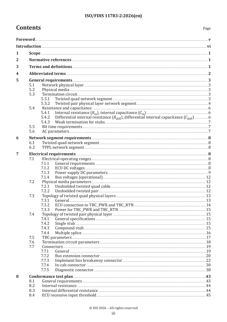
Contents Page
Foreword .v
Introduction .vi
1 Scope . 1
2 Normative references . 1
3 Terms and definitions . 1
4 Abbreviated terms . 2
5 General requirements . 3
5.1 Network physical layer .3
5.2 Physical media .3
5.3 Termination circuit .3
5.3.1 Twisted quad network segment .3
5.3.2 Twisted pair physical layer network segment .4
5.4 Resistance and capacitance .6
5.4.1 Internal resistance (R ), internal capacitance (C ) .6
in in
5.4.2 Differential internal resistance (R ), differential internal capacitance (C ) .6
diff diff
5.4.3 Weak termination for stubs .7
5.5 Bit time requirements .7
5.6 AC parameters.7
6 Network segment requirements . 8
6.1 Twisted quad network segment .8
6.2 TPPL network segment .8
7 Electrical requirements . 8
7.1 Electrical operating ranges .8
7.1.1 General requirements .8
7.1.2 ECU DC voltages .8
7.1.3 Power supply DC parameters .9
7.1.4 Bus voltages (operational) . 12
7.2 Physical media parameters . 12
7.2.1 Unshielded twisted quad cable . . 12
7.2.2 Unshielded twisted pair . 12
7.3 Topology of twisted quad physical layers . 13
7.3.1 General . 13
7.3.2 ECU connection to TBC_PWR and TBC_RTN .14
7.3.3 Power for TBC_PWR and TBC_RTN . 15
7.4 Topology of twisted pair physical layer . 15
7.4.1 General specifications . 15
7.4.2 Single stub . 15
7.4.3 Compound stub . 15
7.4.4 Multiple splice .16
7.5 TBC parameters .17
7.6 Termination circuit parameters .18
7.7 Connectors .19
7.7.1 General .19
7.7.2 Bus extension connector . 20
7.7.3 Implement bus breakaway connector . 22
7.7.4 In-cab connector . 30
7.7.5 Diagnostic connector . 38
8 Conformance test plan .43
8.1 General requirements .43
8.2 Internal resistance . 44
8.3 Internal differential resistance . 44
8.4 ECU recessive input threshold .45
iii
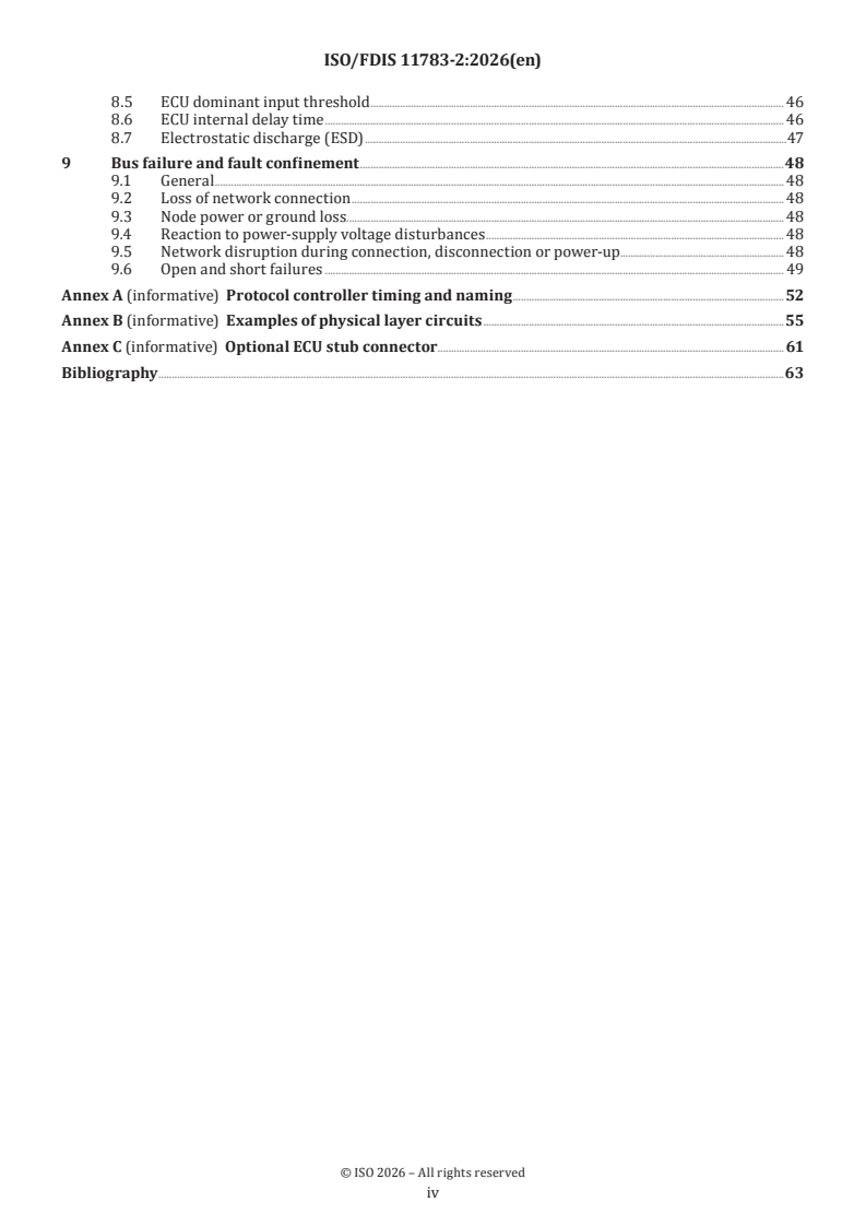
8.5 ECU dominant input threshold . 46
8.6 ECU internal delay time . 46
8.7 Electrostatic discharge (ESD) .47
9 Bus failure and fault confinement .48
9.1 General . 48
9.2 Loss of network connection . 48
9.3 Node power or ground loss. 48
9.4 Reaction to power-supply voltage disturbances . 48
9.5 Network disruption during connection, disconnection or power-up . 48
9.6 Open and short failures . 49
Annex A (informative) Protocol controller timing and naming .52
Annex B (informative) Examples of physical layer circuits .55
Annex C (informative) Optional ECU stub connector . 61
Bibliography .63
iv
Foreword
ISO (the International Organization for Standardization) is a worldwide federation of national standards
bodies (ISO member bodies). The work of preparing International Standards is normally carried out through
ISO technical committees. Each member body interested in a subject for which a technical committee
has been established has the right to be represented on that committee. International organizations,
governmental and non-governmental, in liaison with ISO, also take part in the work. ISO collaborates closely
with the International Electrotechnical Commission (IEC) on all matters of electrotechnical standardization.
The procedures used to develop this document and those intended for its further maintenance are described
in the ISO/IEC Directives, Part 1. In particular, the different approval criteria needed for the different types
of ISO document should be noted. This document was drafted in accordance with the editorial rules of the
ISO/IEC Directives, Part 2 (see www.iso.org/directives).
ISO draws attention to the possibility that the implementation of this document may involve the use of (a)
patent(s). ISO takes no position concerning the evidence, validity or applicability of any claimed patent
rights in respect thereof. As of the date of publication of this document, ISO had not received notice of (a)
patent(s) which may be required to implement this document. However, implementers are cautioned that
this may not represent the latest information, which may be obtained from the patent database available at
www.iso.org/patents. ISO shall not be held responsible for identifying any or all such patent rights.
Any trade name used in this document is information given for the convenience of users and does not
constitute an endorsement.
For an explanation of the voluntary nature of standards, the meaning of ISO specific terms and expressions
related to conformity assessment, as well as information about ISO's adherence to the World Trade
Organization (WTO) principles in the Technical Barriers to Trade (TBT), see www.iso.org/iso/foreword.html.
This document was prepared by Technical Committee ISO/TC 23, Tractors and machinery for agriculture and
forestry, Subcommittee SC 19, Agricultural electronics.
This fourth edition cancels and replaces the third edition (ISO 11783-2:2019), which has been technically
revised.
The main changes are as follows:
— separation of requirements for ECU designers and for system designers;
— updating of electrical requirements to the current state of the art;
— restructuring and rationalization of the document.
A list of all the parts in the ISO 11783 series can be found on the ISO website.
Any feedback or questions on this document should be directed to the user’s national standards body. A
complete listing of these bodies can be found at www.iso.org/members.html.
v
Introduction
The ISO 11783 series specifies a communications system for agricultural equipment based on the ISO 11898-1
CAN protocol. The SAE J1939 series1), on which parts of ISO 11783 series are based, were developed jointly
for use in truck and bus, construction, and agriculture applications. Joint documents have been completed
to allow electronic units that meet the truck and bus SAE J1939 specifications to be used by agricultural
and forestry equipment with minimal changes. General information on the ISO 11783 series can be found in
ISO 11783-1.
The purpose of the ISO 11783 series is to provide an open, interconnected system for on-board electronic
systems. It is intended to enable electronic control units (ECUs) to communicate with each other, providing
a standardized system.
vi
FINAL DRAFT International Standard ISO/FDIS 11783-2:2026(en)
Tractors and machinery for agriculture and forestry — Serial
control and communications data network —
Part 2:
Physical layer
IMPORTANT — This document contains colours which are considered to be useful for the correct
understanding of the document. Users should therefore consider printing this document using a
colour printer.
1 Scope
This document specifies the device interface using the CAN HS (high-speed) physical medium attachment
(PMA) sublayer, as given in ISO 11898-2, and the physical coding sublayer (PCS), as given in ISO 11898-1. It
specifies two physical medium-dependent sublayers:
a) un-shielded, twisted-quad cable, and
b) un-shielded, twisted-pair cable.
NOTE Where not otherwise specified, requirements are valid for both twisted quad physical layer (TQPL) and
twisted pair physical layer (TPPL).
2 Normative references
The following documents are referred to in the text in such a way that some or all of their content constitutes
requirements of this document. For dated references, only the edition cited applies. For undated references,
the latest edition of the referenced document (including any amendments) applies.
ISO 1724, Road vehicles — Connectors for the electrical connection of towing and towed vehicles — 7-pole
connector type 12 N (normal) for vehicles with 12 V nominal supply voltage
ISO 11783-1, Tractors and machinery for agriculture and forestry — Serial control and communications data
network — Part 1: General standard for mobile data communication
ISO 11898-1:2024, Road vehicles — Controller area network (CAN) — Part 1: Data link layer and physical coding
sublayer
ISO 11898-2:2026, Road vehicles — Controller area network (CAN) — Part 1: High-speed physical medium
attachment (PMA) sublayer
S A E J1939 -15: 2018 , Physical Layer, 250 Kbps, Un-Shielded Twisted Pair (UTP)
3 Terms and definitions
For the purposes of this document, the terms and definitions given in ISO 11783-1 and the following apply.
ISO and IEC maintain terminology databases for use in standardization at the following addresses:
— ISO Online browsing platform: available at https:// www .iso .org/ obp
— IEC Electropedia: available at https:// www .electropedia .org/
3.1
ECU Type I
electronic control unit without internal termination
3.2
ECU Type I WEAK
electronic control unit with split termination coupled to ECU_GND with a capacitor and that is used for stubs
only (see 5.4.3)
3.3
ECU Type II
electronic control unit with a internal termination circuit
3.4
internal delay time
the sum of all asynchronous delays that occur along the transmission and reception path within the ECU,
relative to the bit timing logic unit of the CAN implementation (see A.2)
3.5
twisted pair physical layer
TPPL
250 kbit/s, unshielded, twisted pair cable-based network layer intended to be used as an alternate to the
twisted quad physical layer and that is backward compatible with machines based on a twisted quad
physical layer
3.6
machine
forestry or agricultural tractor or mounted, semi-mounted, towed or self-propelled implement
3.7
network segment
single CAN network using a linear topology configuration with stubs
3.8
node
assembly, linked to a communication network, capable of communicating across the network according to a
communication protocol specification
Note 1 to entry: A node can be in one of four states: integrating, idle, receiver or transmitter.
Note 2 to entry: A node operating in a controller area network (CAN) is called a CAN node.
[SOURCE: ISO 11898-1:2024, 3.39, modified — definition has been modified to exclude further information.]
3.9
twisted quad physical layer
TQPL
250 kbit/s, unshielded, twisted quad cable-based network layer
4 Abbreviated terms
IBBC Implement Bus Breakaway Connector (socket)
IBBP Implement Bus Breakaway Plug
CAN controller area network
PMA physical medium attachment
PCS physical Coding Sublayer
ECU Electronic Control Unit
PWR power
GND ground
DC direct current
MDI medium dependent interface
AC alternating Current
TBC Terminating Bias Circuit
TBC_GND Terminating Bias Circuit Ground
TBC_RTN Terminating Bias Circuit Return
5 General requirements
5.1 Network physical layer
The physical coding sublayer shall be in accordance with CAN CC requirements as given in ISO 11898-1:2024,
Clause 7; it is implemented in CAN protocol controller units using a non-return-to-zero (NRZ) coding. The
physical medium attachment (PMA) sublayer shall be in accordance with the requirements for high-speed
PMA entities supporting bit rates up to 1 Mbit/s as given in ISO 11898-2:2026, Table 15 in particular); it is
implemented in so-called high-speed (HS) CAN transceiver units.
The physical medium-dependent (PMD) sublayer is specified in the following subclauses. This includes
requirements for the ECU designer: 5.4, 5.5, 7.1.2, 7.1.3.5, 7.1.3.5.
The requirements for network designers are given in: 5.2, 5.3, Clause 6, 7.1.3.1, 7.1.3.2, 7.1.3.3, 7.1.3.4, 7.1.4,
7.2, 7.3, 7.4, 7.5, 7.6, 7.7.
5.2 Physical media
This document defines two types of physical media.
a) TQPL: shall be composed by four conductors, two of them, designated CAN_H and CAN_L, are driven
with the electrical communication signals. The names of the ECU connector pins corresponding to these
conductors are also designated CAN_H and CAN_L. The third and fourth conductors, designated TBC_
PWR and TBC_RTN, provide power for the terminating bias circuits (TBCs) on the network segment.
b) TPPL: shall be composed by a twisted pair cable as described in SAE J1939-15. The conductors,
designated CAN_H and CAN_L, are driven with the MDI as specified in ISO 11898-2. The names of the
ECU connector pins corresponding to these conductors are also designated CAN_H and CAN_L.
5.3 Termination circuit
5.3.1 Twisted quad network segment
The bus signal lines of a twisted quad network segment shall be electrically terminated at each end by a
terminating bias circuit. When a node transceiver is on, a current (I) flow is induced that is either sunk by
the CAN_H termination or is sourced by the CAN_L termination. This TBC shall be located outside the ECU
housing, to ensure bus bias and termination when the ECU is disconnected (see Figure 1).
Key
1 ECU no. 1
2 ECU no. n
3 terminating bias circuit (TBC)
4 power for TBC_PWR and TBC_RTN
5 twisted quad cable
Figure 1 — Physical layer functional diagram
5.3.2 Twisted pair physical layer network segment
The bus signal lines of a TPPL network segment shall be electrically terminated at each end using a
terminating resistor R (see Figure 2) or with a passive split termination circuit using two resistors R
t tCAN_H
and R coupled to ground by a capacitor C (see Figure 4). 7.6 defines electrical requirements for the
tCAN_L split
two alternatives.
Figure 3 shows the termination for a network segment, using Type II ECUs.
The system designer should take care that the network segment is terminated at one or both ends. Type II
ECUs shall be marked. A Type II ECU shall only be used at one or both ends of a bus, even when the machine
is attached to another machine by an IBBC. Type II ECUs shall only be powered by ECU_PWR/ECU_GND.
Key
1 ECU Type I No. 1
2 ECU Type I No. n
3 unshielded twisted pair
4 terminating resistors R
t
Figure 2 — TPPL passive termination circuit by using single resistors at each end of the network
segment
Key
1 ECU Type I
2 ECU Type II with internal R
t
3 unshielded twisted pair
Figure 3 — TPPL passive termination circuit (one side) by using an ECU Type II as a termination
Key
1 ECU Type II or passive bus termination
2 resistor R
tCAN_H
3 resistor R
tCAN_L
4 coupling capacitor C
split
Figure 4 — TPPL passive termination circuit (one side) by using a split termination
5.4 Resistance and capacitance
5.4.1 Internal resistance (R ), internal capacitance (C )
in in
The internal resistance, R , of an ECU is defined as the resistance between CAN_H or CAN_L and ground
in
(ECU_GND) in the recessive state, with the ECU disconnected from CAN_H and CAN_L. The measurement
shall be made with the ECU both powered and unpowered, and the minimum value shall be used to confirm
conformity.
The internal capacitance, C , of an ECU is defined as the internal capacitance between CAN_H or CAN_L and
in
ECU_GND during the recessive state, with the ECU disconnected from CAN_H and CAN_L. The measurement
shall be made with the ECU both powered and unpowered, and the maximum value shall be used to confirm
conformity.
Figure 5 shows the equivalent circuit of internal resistance and internal capacitance of an ECU.
Key
1 ECU
2 internal resistance R
in
3 internal capacitance C
in
Figure 5 — Internal resistance and internal capacitance of ECU in recessive state
5.4.2 Differential internal resistance (R ), differential internal capacitance (C )
diff diff
The differential internal resistance, R , is defined as the resistance seen between CAN_H and CAN_L in the
diff
recessive state, with the ECU disconnected from CAN_H and CAN_L. The measurement shall be made with
the ECU both powered and unpowered, and the minimum value shall be used to confirm conformity.
The differential internal capacitance, C , of an ECU is defined as the capacitance seen between CAN_H and
diff
CAN_L during the recessive state, with the ECU disconnected from CAN_H and CAN_L (see Figure 6). The
measurement shall be made with the ECU both powered and unpowered, and the maximum value shall be
used to confirm conformity.
Figure 6 shows the equivalent circuit of differential internal resistance and differential internal capacitance
of an ECU.
Key
1 ECU
2 differential internal capacitance C
diff
3 differential internal resistance R
diff
Figure 6 — Differential internal resistance and capacitance of ECU in recessive state
5.4.3 Weak termination for stubs
For higher immunity and better EMC performance, TPPL nodes which are connected to the bus may
be realized by using ECU Type I WEAK equipped with a split-termination circuit. In this case the split-
termination shall be realized by using two 750 Ω resistors coupled to ECU_GND by a 47 nF capacitor. The
total number of ECUs Type I WEAK used on a single network segment shall not exceed three units.
In case a ECU Type I WEAK is powered by the PWR/GND lines, the split termination shall be coupled with
GND.
5.5 Bit time requirements
Bus management functions executed within this duration, such as protocol controller synchronization,
network transmission delay compensation and sample point positioning, are specified by the programmable
bit timing logic of the CAN protocol-controller conformant to ISO 11898-1.
Bit rate shall be 250 kbit/s, resulting in a bit time of 4 µs.
Additionally, the following settings shall be configured:
— single sample point method as defined in ISO 11898-1;
— sample point at 80 % ± 3 % of the bit time.
See Annex A for more details.
5.6 AC parameters
Table 1 specifies the AC parameters for an ECU disconnected from the bus. The timing parameters also apply
for an ECU connected to a network segment.
Table 1 — AC parameters of a node disconnected from the bus
Parameter Symbol Min. Nom. Max. Unit Condition
Bit time t 3,998 4,000 4,002 µs 250 kbit/s
B
Measured from 10 % to 90 %
Transition time t — — 500 ns of the voltage of the prevailing
T
state
Internal delay time t 0,0 — 0,9 µs None
ECU
Internal capacitance single ended C 0 — 200 pF 1 MHz
in
Differential internal capacitance C 0 — 100 pF 1 MHz
diff
CMR 40 — — dB DC. to 50 kHz
Common mode rejection
5 MHz may linearly decrease
CMR 10 — — dB
5MHz
between 50 kHz and 5 MHz
6 Network segment requirements
6.1 Twisted quad network segment
A linear twisted quad network segment shall be terminated at each end by a TBC (see Figure 1 and 7.5). The
TBC provides the electrical bias and common mode termination needed to suppress reflections.
The network segment is in the recessive state if the transmitters of all nodes are switched off, with the
mean voltage being generated by the TBCs. A dominant voltage level is sent to the bus signal lines if the
transmitter of at least one of the nodes is switched on. This induces a current through each side of the TBCs,
with the consequence that a differential voltage is produced between the CAN_H and CAN_L lines.
6.2 TPPL network segment
A linear TPPL network segment shall be terminated at each end by a passive termination circuit (see 5.3.2)
to suppress reflections.
The network segment is in the recessive state if the transmitters of all nodes are switched off. A dominant bit
is sent to the bus signal lines if the transmitter of at least one of the nodes is switched on so that a differential
voltage is produced between the CAN_H and CAN_L lines.
7 Electrical requirements
7.1 Electrical operating ranges
7.1.1 General requirements
ECUs shall comply with parameters specified in Table 1, Table 2, Table 7, Table 8, Table 9 and Table 10
throughout their operating temperature range.
7.1.2 ECU DC voltages
Table 2 specifies the absolute maximum DC voltages which can be connected to the bus signal lines without
damage to nodes.
Table 2 — Limits of V and V of bus-disconnected ECU
CAN_H CAN_L
Parameter Symbol Minimum Maximum Unit Conditions
V
CAN_H
Maximum DC voltage −16,0 +16,0 V 12 V nominal supply voltage
V
CAN_L
7.1.3 Power supply DC parameters
7.1.3.1 Architecture power supply DC voltages
Table 3 specifies limits of power supply operating ranges when the nominal supply voltage is 12 V when
considering the system power architecture.
Table 3 — Limits of power supply operating ranges
Parameter Symbol Minimum Maximum Unit Conditions
V
PWR
Voltage operating range +10,0 +16,0 V 12 V nominal supply voltage
V
ECU_PWR
7.1.3.2 Architecture power supply minimum currents
Table 4 specifies the minimum current capacity available from the ECU_PWR and PWR lines when
considering the system power architecture.
Table 4 — Power supply minimum currents
Parameter Symbol Minimum Unit
I 50 A
PWR
Current capacity
I 15 A
ECU_PWR
7.1.3.3 Requirements for DC voltage supplied by tractor through the IBBC
Electrical power on the tractor is supplied by the 12-V supply and alternator system to various electrical
loads on the tractor and implement. To ensure that the tractor can adequately supply electrical power to the
implement, the voltage requirements specified in Table 5 and Table 6 apply at the IBBC/TPPL-BC electrical
supply terminals.
The minimum current available from the tractor implement bus ECU_PWR/ECU_GND lines shall be 15 A
under conditions specified in Table 5.
Table 5 — ECU_PWR limits at tractor IBBC/TPPL-BCs
Parameter Symbol Min Max Unit
ECU power line voltage V 10,5 16,0 V
ECU_DIFF
Conditions for measurement:
— V = V - V
ECU_DIFF ECU_PWR ECU_GND
— Measured at tractor IBBC/TPPL-BC terminals
— 15 A DC electrical load
−1
— Engine at normal operating min range (as defined by manufacturer)
— Tractor electrical loads on (lights, fans, etc.)
— Operating temperature range: -30 °C to 85 °C
The minimum current available from the tractor implement bus PWR/GND lines shall be 50 A under the
conditions specified in Table 6.
Table 6 — PWR limits at tractor IBBC/TPPL-BCs
Power line voltage Min Max Unit
V – V 10,5 16,0 V
PWR GND
Conditions for measurement:
— Measured at tractor IBBC/TPPL-BC terminals
— 50 A DC electrical load
−1
— Engine at normal operating min range (as defined by manufacturer)
— Tractor electrical loads on (lights, fans, etc.)
— Operating temperature range: -30 °C to 85 °C
Maximum simultaneous combined current drawn by an implement through the IBBC shall not exceed 55 A
(continuous current).
NOTE Higher combined currents result in high temperature which can damage the connector or pins.
7.1.3.4 Requirements for DC voltage drop on implements
Electrical power on an implement is supplied by the PWR and ECU_PWR lines through the IBBC.
The implement can provide a rear IBBC receptacle to allow daisy chain connection of additional implements
that acts like electrical loads.
In case of a daisy chain connection, if the voltage drops due to the resistance of supply and return leads on an
implement is too high, the following implement may experience an insufficient operating voltage for correct
operation. To avoid such a situation, and to ensure that an implement can adequately supply electrical power
to the following one, the maximum allowed voltage drop on an implement shall be in accordance to Table 7
and the implement minimum supplied currents shall be in accordance to 7.1.3.2.
Table 7 — Maximum allowed voltage drop in an implement
Power lines voltage Min Max Unit
Implement voltage drop on ECU_
— 1,5 V
a
PWR/ECU_GND lines
Implement voltage drop on PWR/
— 1,5 V
b
GND lines
a
15 A provided at the implement rear IBBC.
b
50 A provided at the implement rear IBBC.
Conditions for measurement (see Figure 7):
— Measured between implement plug and implement rear IBBC
— Any load on the implement under test shall be disconnected
— 1,5 V is the total drop of both power supply and return path
— Operating temperature range: -30 °C to 85 °C
Figure 7 — Voltage-drop measurement
7.1.3.5 Bus-disconnected ECU
The DC parameters for the recessive state of the CAN interface of a powered ECU disconnected from the bus
are specified in Table 8.
Table 8 — DC parameters for recessive state of bus-disconnected ECUs
Parameter Symbol Min. Nom. Max. Unit
V
CAN_H
Bus voltage output behaviour 2,0 2,5 3,0 V
V
CAN_L
Differential output voltage behaviour V −1 200 — 50 mV
diff
g
Differential internal resistance (Type I ECU only) R 2 — 100 kΩ
diff
g
Internal resistance (Type I ECU only) R 5 — 50 kΩ
in
Internal resistance match — −5 — 5 %
Input differential voltage detected as reces- —
V −1,0 0,5 V
diff_IR
sive
The DC parameters for the dominant state of the CAN interface of an ECU disconnected from the bus are
specified in Table 9.
Table 9 — DC parameters for dominant state of bus-disconnected ECUs
Parameter Symbol Min. Max. Unit
V 2,75 5,0
CAN_H
Bus voltage
V 0,0 2,25
CAN_L
V
Differential output voltage V 1,5 3,0
diff_OD
Differential voltage detected as dominant V 1,0 5,0
diff_ID
7.1.3.6 Bus-connected ECU
The DC parameters for the recessive state of the CAN interface of an ECU connected to a network segment
and other ECUs are specified in Table 10.
Table 10 — DC parameters (bus voltage) for bus-connected ECUs in recessive state, without faults
Parameter Symbol Min. Max. Unit Conditions
V
CAN_H
Bus voltage 0,1 4,5 V Measured with respect to GND of each ECU
V
CAN_L
Differential bus voltage V −1 200 50 mV Measured at each ECU connected to CAN_H and CAN_L
diff_R
The DC parameters for the dominant state of the CAN interface of an ECU connected to a network segment
and other ECUs is specified in Table 11.
Table 11 — DC parameters (bus voltage) for bus-connected ECUs in dominant state, without faults
Parameter Symbol Min. Max. Unit Conditions
V — 7,0
CAN_H
Bus voltage V Measured with respect to GND of each ECU
V −2,0 —
CAN_L
3,0 Measured at each ECU connected to bus signal lines
Differential bus voltage V 1,2 V
diff
5,0 During arbitration
7.1.4 Bus voltages (operational)
The bus voltage parameters specified in Table 11 apply when all ECUs (from 2 to 30) are connected to a
terminated network segment (see 5.3). The maximum expected ground offset between ECUs or ECUs and
TBCs on the bus is 2 V.
7.2 Physical media parameters
7.2.1 Unshielded twisted quad cable
Table 12 specifies the physical media parameters for the twisted quad cable (see Figure 9).
Table 12 — Physical media parameters for twisted quad cable
Parameter Symbol Min. Max. Unit Conditions
Measured at 1 MHz between either
Z
H
Impedance 70 80 Ω signal line and ground with TBC_PWR
Z
L
and TBC_RTN grounded
Specific resistance R 0 50 mΩ/m Measured at 20 °C
b
Specific line delay T — — ns/m —
p
C 0 75 pF/m Between CAN_H and CAN_L
b
Specific capacitance
C 0 110 pF/m Between adjacent conductors
a
Cross-section to be formed from 16 or
Conductor size A — — mm greater strands of 32 AWG tinned or
c
bare copper.
Conductor twist — 48 52 mm/turn —
Continuous operation without degra-
Temperature range T −40 +85 °C
dation
Table 13 recommends colours for the insulation of the wires in the cable. The manufacturer is recommended
to provide a detailed description of wires colour in the technical documentation.
Table 13 — Recommended colours for conductor insulation
Colour Conductor insulation
Red TBC_PWR
Yellow CAN_H
Black TBC_RTN
Green CAN_L
7.2.2 Unshielded twisted pair
Table 14 specifies the physical media parameters for unshielded twisted pair cable (see Figure 8).
Table 14 — Physical media parameters for twisted pair cable
Parameter Symbol Min. Nom. Max. Unit Conditions
Three-meter sample length meas-
ured at 1 MHz between the two
Impedance Z 108 120 132 Ω
signal wires, using open/short
method.
Specific resistance R — 25 50 mΩ/m Measured at 20 °C
b
Specific line delay T — 5,0 — ns/m
p
C — 40 75 pF/m Between CAN_H and CAN_L
b
Specific capacitance
Conductor twist — 24 — 52 mm/turn —
Temperature range T −40 — +85 °C
Key
1 unshielded twisted quad
2 unshielded twisted pair
A conductor size
c
D conductor insulation diameter
ci
T Jacket size
j
Figure 8 — Cable cross-section
The bus line consists of CAN_H and CAN_L conductors. Table 15 specifies the recommended wire jacket
colours for the CAN_H and CAN_L (see Figure 8).
Table 15 — Recommended colours for conductor insulation
Colour Conductor insulation
Yellow CAN_H
Green CAN_L
7.3 Topology of twisted quad physical layers
7.3.1 General
To avoid cable reflections, the wiring of a network segment should have a bus line topology with short stubs
(see Figure 10). To minimize standing waves, nodes should have different distances (d) on the network
segment and stub lengths should have different lengths (S). The dimensional parameters of this topology as
shown in Figure 10 are specified in Table 16.
Consider not to cluster nodes.
Key
1 terminating bias circuit (TBC)
2 2 wires, CAN_H and CAN_L
3 twisted quad cable
4 ECU 1
5 ECU 2
6 ECU n-1
7 ECU n
d distance between two nodes (see Table 16)
S stub length (see Table 16)
l end to end bus length (see Table 16)
bus
Figure 9 — Topology of bus-segment wiring
Table 16 — Topology dimensional parameters
Parameter Symbol Min. Max Unit Conditions
Bus length l - 40 m Not including stubs
bus
Stub length S 0 1 m —
Node distance d 0,1 - m Random
7.3.2 ECU connection to TBC_PWR and TBC_RTN
To sense the status of the network, each ECU on the bus can provide a pin for TBC_PWR and TBC_RTN.
Loading limits are specified in Table 17.
Table 17 — ECU loading of TBC_PWR and TBC_RTN
Parameter Symbol Min. Max. Unit Conditions
Measured between TBC_PWR and any other signal
R 30 — kΩ
TBC_PWR
in ECU
DC resistance
R 30 — kΩ Measured between TBC_RTN and any other signal in ECU
TBC_RTN
Measured at 1 MHz between TBC_PWR and any other
C — 200 nF
TBC_PWR
signal in ECU
Capacitance
Measured at 1 MHz between TBC_RTN and any other
C — 200 nF
TBC_RTN
signal in ECU
7.3.3 Power for TBC_PWR and TBC_RTN
TBC_PWR and TBC_RTN for a given network segment shall be supplied at a single point. This sin
...
TC /SC ISO/FDIS 11783-2
ISO/TC 23/SC 19
Secretariat: DIN
i
Date: 2026-09-25
Tractors and machinery for agriculture and forestry — Serial control
and communications data network —
Part 2:
Physical layer
Tracteurs et matériels agricoles et forestiers — Réseaux de commande et de communication de données en
série —
Partie 2: Couche physique
FDIS stage
All rights reserved. Unless otherwise specified
This ISO publication is protected by copyright and is owned by ISO and/or its licensors.
The content of this ISO publication is provided under licence, not sold. Use is subject to the applicable licence terms issued
by ISO, an ISO member body, or an authorized third-party distributor.
Except as required for implementation or expressly permitted by a separate licence, no part of this ISO publication may
be reproduced or utilized otherwise, distributed, modified, used, or made available in any form or by any means, –
electronic or mechanical, including photocopying, scanning, recording, or posting on the internet or an intranet, without
prior written permission. Permission can be requested from either ISO atinternal or external digital platforms.
Any use beyond the address below or ISO’s member body in scope of the country of the requestergranted rights is
prohibited and may result in legal action.
ISO copyright office
Ch. de Blandonnet 8 • CP 401 • CH-1214 Vernier, Geneva, Switzerland
Tel.Phone: + 41 22 749 01 11
Fax + 41 22 749 09 47
Email: copyright@iso.org
Website: www.iso.org
Published in Switzerland
iii
Contents Page
Foreword . v
Introduction . vi
1 Scope . 1
2 Normative references . 1
3 Terms and definitions . 1
4 Abbreviated terms . 3
5 General requirements . 3
5.1 Network physical layer . 3
5.2 Physical media . 3
5.3 Termination circuit . 4
5.4 Resistance and capacitance . 8
5.5 Bit time requirements . 10
5.6 AC parameters . 11
6 Network segment requirements . 11
6.1 Twisted quad network segment . 11
6.2 TPPL network segment . 11
7 Electrical requirements . 11
7.1 Electrical operating ranges . 11
7.2 Physical media parameters . 16
7.3 Topology of twisted quad physical layers . 18
7.4 Topology of twisted pair physical layer . 20
7.5 TBC parameters . 23
7.6 Termination circuit parameters . 24
7.7 Connectors . 25
8 Conformance test plan . 71
8.1 General requirements . 71
8.2 Internal resistance . 71
8.3 Internal differential resistance . 73
8.4 ECU recessive input threshold . 73
8.5 ECU dominant input threshold. 74
8.6 ECU internal delay time . 75
8.7 Electrostatic discharge (ESD) . 77
9 Bus failure and fault confinement . 77
9.1 General. 77
9.2 Loss of network connection . 77
9.3 Node power or ground loss . 77
9.4 Reaction to power-supply voltage disturbances . 77
9.5 Network disruption during connection, disconnection or power-up . 78
9.6 Open and short failures . 78
Annex A (informative) Protocol controller timing and naming . 83
Annex B (informative) Examples of physical layer circuits . 87
Annex C (informative) Optional ECU stub connector . 98
Bibliography . 101
iv
Foreword
ISO (the International Organization for Standardization) is a worldwide federation of national standards
bodies (ISO member bodies). The work of preparing International Standards is normally carried out through
ISO technical committees. Each member body interested in a subject for which a technical committee has been
established has the right to be represented on that committee. International organizations, governmental and
non-governmental, in liaison with ISO, also take part in the work. ISO collaborates closely with the
International Electrotechnical Commission (IEC) on all matters of electrotechnical standardization.
The procedures used to develop this document and those intended for its further maintenance are described
in the ISO/IEC Directives, Part 1. In particular, the different approval criteria needed for the different types of
ISO documentsdocument should be noted. This document was drafted in accordance with the editorial rules
of the ISO/IEC Directives, Part 2 (see www.iso.org/directives).
Attention is drawnISO draws attention to the possibility that some of the elementsimplementation of this
document may beinvolve the subjectuse of (a) patent(s). ISO takes no position concerning the evidence,
validity or applicability of any claimed patent rights in respect thereof. As of the date of publication of this
document, ISO had not received notice of (a) patent(s) which may be required to implement this document.
However, implementers are cautioned that this may not represent the latest information, which may be
obtained from the patent database available at www.iso.org/patents. ISO shall not be held responsible for
identifying any or all such patent rights. Details of any patent rights identified during the development of the
document will be in the Introduction and/or on the ISO list of patent declarations received (see ).
Any trade name used in this document is information given for the convenience of users and does not
constitute an endorsement.
For an explanation onof the voluntary nature of standards, the meaning of ISO specific terms and expressions
related to conformity assessment, as well as information about ISO's adherence to the World Trade
Organization (WTO) principles in the Technical Barriers to Trade (TBT)), see
www.iso.org/iso/foreword.htmlthe following URL: .
This document was prepared by Technical Committee ISO/TC 23, Tractors and machinery for agriculture and
forestry, Subcommittee SC 19, Agricultural electronics.
This fourth edition cancels and replaces the third edition (ISO 11783-2:2019), which has been technically
revised. It also incorporates the Technical Corrigendum ISO 11783-2:2012/Cor 1:2012. The main changes
compared to the previous edition are as follows:
— The main changes are as follows:
— separation of requirements for ECU designers and for system designers;
— — updateupdating of electrical requirements to the current state of the art;
— — alignment of the document to ISO/IEC directives;
— — restructuring and rationalization of the document.
A list of all the parts in the ISO 11783 series can be found on the ISO website.
Any feedback or questions on this document should be directed to the user’s national standards body. A
complete listing of these bodies can be found at www.iso.org/members.html.
v
Introduction
The ISO 11783 series specifies a communications system for agricultural equipment based on the ISO 11898-
1 CAN protocol. The SAE J1939 series1), on which parts of ISO 11783 series are based, were developed jointly
for use in truck and bus, construction, and agriculture applications. Joint documents have been completed to
allow electronic units that meet the truck and bus SAE J1939 specifications to be used by agricultural and
forestry equipment with minimal changes. General information on the ISO 11783 series can be found in ISO
11783-1.
The purpose of the ISO 11783 series is to provide an open, interconnected system for on-board electronic
systems. It is intended to enable electronic control units (ECUs) to communicate with each other, providing a
standardized system.
vi
Tractors and machinery for agriculture and forestry — Serial control
and communications data network —
Part 2:
Physical layer
IMPORTANT — This document contains colours which are considered to be useful for the correct
understanding of the document. Users should therefore consider printing this document using a
colour printer.
1 Scope
This document specifies the device interface using the CAN HS (high-speed) physical medium attachment
(PMA) sublayer, as given in ISO 11898-2, and the physical coding sublayer (PCS)), as given in ISO 11898-1.
Additionally, this documentIt specifies two physical medium-dependent sublayers: a) un-shielded, twisted-
quad cable and b) un-shielded, twisted-pair cable.
a) un-shielded, twisted-quad cable, and
a)b) un-shielded, twisted-pair cable.
NOTE Where not differentlyotherwise specified, requirements are valid for both twisted quad physical layer (TQPL)
and twisted pair physical layer (TPPL).
2 Normative references
The following documents are referred to in the text in such a way that some or all of their content constitutes
requirements of this document. For dated references, only the edition cited applies. For undated references,
the latest edition of the referenced document (including any amendments) applies.
ISO 1724:2003, Road vehicles — Connectors for the electrical connection of towing and towed vehicles — 7-pole
connector type 12 N (normal) for vehicles with 12 V nominal supply voltage
ISO 11783-1:2017, Tractors and machinery for agriculture and forestry — Serial control and communications
data network — Part 1: General standard for mobile data communication
ISO 11898-1:2024, Road vehicles — Controller area network (CAN) — Part 1: Data link layer and physical coding
sublayer
ISO 11898-2:20242026, Road vehicles — Controller area network (CAN) — Part 1: High-speed physical medium
attachment (PMA) sublayer
SAE J1939-11:2016, Physical Layer, 250 Kbps, Twisted Shielded Pair
SAE J1939-13:2024, Off-Board Diagnostic Connector
SAE J1939-15:2018, Physical Layer, 250 Kbps, Un-Shielded Twisted Pair (UTP)
3 Terms and definitions
For the purposes of this document, the terms and definitions given in ISO 11783-1 and the following apply.
ISO and IEC maintain terminologicalterminology databases for use in standardization at the following
addresses:
— — ISO Online browsing platform: available at https://www.iso.org/obp
— — IEC Electropedia: available at https://www.electropedia.org/
3.1 3.1
ECU Type I
electronic control unit without internal termination
3.2 3.2
ECU Type I WEAK
electronic control unit with split termination coupled to ECU_GND with a capacitor and that is used for stubs
only (see 5.54.3)
Field Code Changed
3.3 3.3
ECU Type II
electronic control unit with a internal termination circuit
3.4 3.4
internal delay time
the sum of all asynchronous delays that occur along the transmission and reception path within the ECU,
relative to the bit timing logic unit of the CAN implementation (see A.2)
Field Code Changed
3.5 3.5
twisted pair physical layer
TPPL
250 kbit/s, unshielded, twisted pair cable-based network layer intended to be used as an alternate to the
twisted quad physical layer and that is backward compatible with machines based on a twisted quad physical
layer
3.6 3.6
machine
forestry or agricultural tractor or mounted, semi-mounted, towed or self-propelled implement
3.7 3.7
network segment
single CAN network using a linear topology configuration with stubs
3.8
3.8
node
see definition assembly, linked to a communication network, capable of communicating across the network
according to a communication protocol specification
Note 1 to entry: A node can be in one of four states: integrating, idle, receiver or transmitter.
Note 2 to entry: A node operating in a controller area network (CAN) is called a CAN node.
[SOURCE: ISO 11898 - -1 Clause:2024, 3.39, modified — definition has been modified to exclude further
information.]
3.9 3.9
twisted quad physical layer
TQPL
250 kbit/s, unshielded, twisted quad cable-based network layer
4 Abbreviated terms
IBBC Implement Bus Breakaway Connector (socket)
IBBP Implement Bus Breakaway Plug
CAN controller area network
PMA physical medium attachment
PCS physical Coding Sublayer
ECU Electronic Control Unit
PWR power
GND ground
DC direct current
MDI medium dependent interface
AC alternating Current
TBC Terminating Bias Circuit
TBC_GND Terminating Bias Circuit Ground
TBC_RTN Terminating Bias Circuit Return
5 General requirements
5.1 Network physical layer
The physical coding sublayer shall complybe in accordance with CAN CC requirements as given in ISO 11898-
1:2024 (, Clause 7);; it is implemented in CAN protocol controller units using a non-return-to-zero (NRZ)
coding. The physical medium attachment (PMA) sublayer shall complybe in accordance with the requirements
for high-speed PMA entities supporting bit rates up to 1 Mbit/s as given in ISO 11898-2:2024 (see2026,
Table 15 in particular); it is implemented in so-called high-speed (HS) CAN transceiver units.
The physical medium-dependent (PMD) sublayer is specified in the following subclauses. This includes
requirements for the ECU designer: 5.4, 5.5, 7.1.2, 7.1.3.5, 7.1.3.5.
Field Code Changed
The requirements for network designers are given in: 5.2, 5.3, Clause 6, 7.1.3.1, 7.1.3.2, 7.1.3.3, 7.1.3.4, 7.1.4,
7.2, 7.3, 7.4, 7.5, 7.6, 7.7, 7.4, 7.5, 7.6, 7.7.
5.2 Physical media
This document defines two types of physical media.
a) a) TQPL: shall be composed by four conductors, two of them, designated CAN_H and CAN_L, are
driven with the electrical communication signals. The names of the ECU connector pins corresponding to
these conductors are also designated CAN_H and CAN_L. The third and fourth conductors, designated
TBC_PWR and TBC_RTN, provide power for the terminating bias circuits (TBCs) on the network segment.
b) b) TPPL: shall be composed by a twisted pair cable as described in SAE J1939-15. The conductors,
designated CAN_H and CAN_L, are driven with the MDI as specified in ISO 11898-2. The names of the ECU
connector pins corresponding to these conductors are also designated CAN_H and CAN_L.
5.3 Termination circuit
5.3.1 Twisted quad network segment
The bus signal lines of a twisted quad network segment shall be electrically terminated at each end by a
terminating bias circuit. When a node transceiver is on, a current (I) flow is induced that is either sunk by the
CAN_H termination or is sourced by the CAN_L termination. This TBC shall be located outside the ECU housing,
to ensure bus bias and termination when the ECU is disconnected (see Figure 1).
Field Code Changed
Key
1 ECU no. 1
2 ECU no. n
3 terminating bias circuit (TBC)
4 power for TBC_PWR and TBC_RTN
5 twisted quad cable
1 ECU no. 1
2 ECU no. n
3 terminating bias circuit (TBC)
4 power for TBC_PWR and TBC_RTN
5 twisted quad cable
Figure 1 — Physical layer functional diagram
5.3.2 Twisted pair physical layer network segment
The bus signal lines of a TPPL network segment shall be electrically terminated at each end using a terminating
resistor R (see Figure 2) or with a passive split termination circuit using two resistors R and R
t tCAN_H tCAN_L
coupled to ground by a capacitor C (see Figure 4). 7.6 defines electrical requirements for the two
split
alternatives.
Figure 3 shows the termination for a network segment, using Type II ECUs.
The system designer should take care that the network segment is terminated at one or both ends. Type II
ECUs shall be marked. A Type II ECU shall only be used at one or both ends of a bus, even when the machine
is attached to another machine by an IBBC. Type II ECUs shall only be powered by ECU_PWR/ECU_GND.
Key
1 ECU Type I No. 1
2 ECU Type I No. n
3 unshielded twisted pair
4 terminating resistors Rt
1 ECU Type I No. 1
2 ECU Type I No. n
3 unshielded twisted pair
4 terminating resistors R
t
Figure — 2 — TPPL passive termination circuit by using single resistors at each end of the network
segment
Key
1 ECU Type I
2 ECU Type II with internal R
t
3 unshielded twisted pair
1 ECU Type I
2 ECU Type II with internal Rt
3 unshielded twisted pair
Figure — 3 — TPPL passive termination circuit (one side) by using an ECU Type II as a termination
Key
1 ECU Type II or passive bus termination
2 Resistor RtCAN_H
3 Resistor RtCAN_L
4 coupling capacitor C
split
1 ECU Type II or passive bus termination
2 resistor RtCAN_H
3 resistor RtCAN_L
4 coupling capacitor Csplit
Figure — 4 — TPPL passive termination circuit (one side) by using a split termination
5.4 Resistance and capacitance
5.4.1 Internal resistance (R ), internal capacitance (C )
in in
The internal resistance, R , of an ECU is defined as the resistance between CAN_H or CAN_L and ground
in
(ECU_GND) in the recessive state, with the ECU disconnected from CAN_H and CAN_L. The measurement shall
be made with the ECU both powered and unpowered, and the minimum value shall be used to confirm
conformity.
The internal capacitance, C , of an ECU is defined as the internal capacitance between CAN_H or CAN_L and
in
ECU_GND during the recessive state, with the ECU disconnected from CAN_H and CAN_L. The measurement
shall be made with the ECU both powered and unpowered, and the maximum value shall be used to confirm
conformity.
Figure 5 shows the equivalent circuit of internal resistance and internal capacitance of an ECU.
Key
1 ECU
2 internal resistance Rin
3 internal capacitance C
in
1 ECU
2 internal resistance Rin
3 internal capacitance Cin
Figure — 5 — Internal resistance and internal capacitance of ECU in recessive state
5.4.2 Differential internal resistance (R ), differential internal capacitance (C )
diff diff
The differential internal resistance, R , is defined as the resistance seen between CAN_H and CAN_L in the
diff
recessive state, with the ECU disconnected from CAN_H and CAN_L. The measurement shall be made with the
ECU both powered and unpowered, and the minimum value shall be used to confirm conformity.
The differential internal capacitance, C , of an ECU is defined as the capacitance seen between CAN_H and
diff
CAN_L during the recessive state, with the ECU disconnected from CAN_H and CAN_L (see Figure 6). The
measurement shall be made with the ECU both powered and unpowered, and the maximum value shall be
used to confirm conformity.
Figure 6 shows the equivalent circuit of differential internal resistance and differential internal capacitance of
an ECU.
Key
1 ECU
2 Differential internal capacitance Cdiff
3 Differential internal resistance Rdiff
1 ECU
2 differential internal capacitance Cdiff
3 differential internal resistance Rdiff
Figure — 6 — Differential internal resistance and capacitance of ECU in recessive state
5.4.3 Weak termination for stubs
For higher immunity and better EMC performance, TPPL nodes which are connected to the bus may be
realized by using ECU Type I WEAK equipped with a split-termination circuit. In this case the split-termination
shall be realized by using two 750 Ω resistors coupled to ECU_GND by a 47 nF capacitor. The total number of
ECUs Type I WEAK used on a single network segment shall not exceed three units.
In case a ECU Type I WEAK is powered by the PWR/GND lines, the split termination shall be coupled with
GND.
5.5 Bit time requirements
Bus management functions executed within this duration, such as protocol controller synchronization,
network transmission delay compensation and sample point positioning, are specified by the programmable
bit timing logic of the CAN protocol-controller conformant to ISO 11898-1.
Bit rate shall be 250 kbit/s, resulting in a bit time of 4 µs.
Additionally, the following settings shall be configured:
— — single sample point method as defined in ISO 11898-1;
— — sample point at 80 % ± 3 % of the bit time.
See Annex A for more details.
5.6 AC parameters
Table 1 specifies the AC parameters for an ECU disconnected from the bus. The timing parameters also apply
for an ECU connected to a network segment.
Table 1 — AC parameters of a node disconnected from the bus
Parameter Symbol Min. Nom. Max. Unit Condition
Bit time tB 3,998 4,000 4,002 µs 250 kbit/s
Measured from 10 % to 90 % of
Transition time tT — — 500 ns the voltage of the prevailing
state
Internal delay time tECU 0,0 — 0,9 µs None
Internal capacitance single
C 0 — 200 pF 1 MHz
in
ended
Differential internal capacitance Cdiff 0 — 100 pF 1 MHz
CMR 40 — — dB DC. to 50 kHz
Common mode rejection
5 MHz may linearly decrease
CMR5MHz 10 — — dB
between 50 kHz and 5 MHz
6 Network segment requirements
6.1 Twisted quad network segment
A linear twisted quad network segment shall be terminated at each end by a TBC (see Figure 1 and 7.5). The
TBC provides the electrical bias and common mode termination needed to suppress reflections.
The network segment is in the recessive state if the transmitters of all nodes are switched off, with the mean
voltage being generated by the TBCs. A dominant voltage level is sent to the bus signal lines if the transmitter
of at least one of the nodes is switched on. This induces a current through each side of the TBCs, with the
consequence that a differential voltage is produced between the CAN_H and CAN_L lines.
6.2 TPPL network segment
A linear TPPL network segment shall be terminated at each end by a passive termination circuit (see 5.3.2) to
suppress reflections.
The network segment is in the recessive state if the transmitters of all nodes are switched off. A dominant bit
is sent to the bus signal lines if the transmitter of at least one of the nodes is switched on so that a differential
voltage is produced between the CAN_H and CAN_L lines.
7 Electrical requirements
7.1 Electrical operating ranges
7.1.1 General requirements
ECUs shall comply with parameters specified in Table 1, Table 2, Table 7, Table 8, Table 7, Table 8, Table 9,
Table 9 and Table 10Table 10 throughout their operating temperature range.
7.1.2 ECU DC voltages
Table 2Table 2 specifies the absolute maximum DC voltages which can be connected to the bus signal lines
without damage to nodes.
Table 2 — Limits of V and V of bus-disconnected ECU
CAN_H CAN_L
Parameter Symbo Minimu Maximu Uni Conditions
l m m t
V
CAN_H
Maximum DC voltage −16,0 +16,0 V 12 V nominal supply voltage
VCAN_L
7.1.3 Power supply DC parameters
7.1.3.1 Architecture power supply DC voltages
Table 3 specifies limits of power supply operating ranges when the nominal supply voltage is 12 V when
considering the system power architecture.
Table 3 — Limits of power supply operating ranges
Parameter Symbol Minimum Maximum Unit Conditions
VPWR
Voltage operating range +10,0 +16,0 V 12 V nominal supply voltage
VECU_PWR
7.1.3.2 Architecture power supply minimum currents
Table 4 specifies the minimum current capacity available from the ECU_PWR and PWR lines when considering
the system power architecture.
Table 4 — Power supply minimum currents
Parameter Symbol Minimu Unit
m
IPWR 50 A
Current capacity
I 15 A
ECU_PWR
7.1.3.3 Requirements for DC voltage supplied by tractor through the IBBC
Electrical power on the tractor is supplied by the 12-V supply and alternator system to various electrical loads
on the tractor and implement. To ensure that the tractor can adequately supply electrical power to the
implement, the voltage requirements specified in Table 5 and Table 6 apply at the IBBC/TPPL-BC electrical
supply terminals.
The minimum current available from the tractor implement bus ECU_PWR/ECU_GND lines shall be 15 A under
conditions specified in Table 5.
Field Code Changed
Table 5 — ECU_PWR limits at tractor IBBC/TPPL-BCs
Parameter Symbol Min Max Unit
ECU power line V
ECU_DIFF
10,5 16,0 V
voltage
Parameter Symbol Min Max Unit
Conditions for measurement:
— VECU_DIFF = VECU_PWR - VECU_GND
— Measured at tractor IBBC/TPPL-BC terminals
— 15 A DC electrical load
−1
— Engine at normal operating min range (as defined by manufacturer)
— Tractor electrical loads on (lights, fans, etc.)
— Operating temperature range: -30 °C to 85 °C
The minimum current available from the tractor implement bus PWR/GND lines shall be 50 A under the
conditions specified in Table 6.
Field Code Changed
Table 6 — PWR limits at tractor IBBC/TPPL-BCs
Power line voltage Min Max Unit
VPWR – VGND 10,5 16,0 V
Conditions for measurement:
— Measured at tractor IBBC/TPPL-BC terminals
— 50 A DC electrical load
−1
— Engine at normal operating min range (as defined by manufacturer)
— Tractor electrical loads on (lights, fans, etc.)
— Operating temperature range: -30 °C to 85 °C
Maximum simultaneous combined current drawn by an implement through the IBBC shall not exceed 55 A
(continuous current).
NOTE : Higher combined currents would result in high temperature which can damage the connector or pins.
7.1.3.4 Requirements for DC voltage drop on implements
Electrical power on an implement is supplied by the PWR and ECU_PWR lines through the IBBC.
The implement can provide a rear IBBC receptacle to allow daisy chain connection of additional implements
that acts like electrical loads.
In case of a daisy chain connection, if the voltage drops due to the resistance of supply and return leads on an
implement is too high, the following implement may experience an insufficient operating voltage for correct
operation. To avoid such a situation, and to ensure that an implement can adequately supply electrical power
to the following one, the maximum allowed voltage drop on an implement shall be in accordance to Table 7
and the implement minimum supplied currents shall be in accordance to 7.1.3.2.
Field Code Changed
Table 7 — Maximum allowed voltage drop in an implement
Power lines voltage Min Max Unit
Implement voltage drop on
— 1,5 V
a
ECU_PWR/ECU_GND lines
Implement voltage drop on PWR/
— 1,5 V
b
GND lines
a 15 A provided at the implement rear IBBC.
b 50 A provided at the implement rear IBBC.
Conditions for measurement (see Figure 7Figure 7):):
Power lines voltage Min Max Unit
— Measured between implement plug and implement rear IBBC
— Any load on the implement under test shall be disconnected
— 1,5 V is the total drop of both power supply and return path
— Operating temperature range: -30 °C to 85 °C
Figure 7 — Voltage-drop measurement
7.1.3.5 Bus-disconnected ECU
The DC parameters for the recessive state of the CAN interface of a powered ECU disconnected from the bus
are specified in Table 8.
Field Code Changed
Table 8 — DC parameters for recessive state of bus-disconnected ECUs
Parameter Symbol Min. Nom. Max. Unit
VCAN_H
Bus voltage output behaviour 2,0 2,5 3,0 V
V
CAN_L
−12001 —
Differential output voltage behaviour Vdiff 50 mV
Differential internal resistance (Type I ECU —
Rdiff 2 100 kΩ
g
only)
g
Internal resistance (Type I ECU only) Rin 5 — 50 kΩ
Internal resistance match — −5 — 5 %
Parameter Symbol Min. Nom. Max. Unit
Input differential voltage detected as —
V −1,0 0,5 V
diff_IR
recessive
The DC parameters for the dominant state of the CAN interface of an ECU disconnected from the bus are
specified in Table 9.
Field Code Changed
Table 9 — DC parameters for dominant state of bus-disconnected ECUs
Parameter Symbol Min. Max. Unit
V 2,75 5,0
CAN_H
Bus voltage
V 0,0 2,25
CAN_L
V
Differential output voltage V 1,5 3,0
diff_OD
Differential voltage detected as dominant V 1,0 5,0
diff_ID
7.1.3.6 Bus-connected ECU
The DC parameters for the recessive state of the CAN interface of an ECU connected to a network segment and
other ECUs are specified in Table 10.
Field Code Changed
Table 10 — DC parameters (bus voltage) for bus-connected ECUs in recessive state, without faults
Parameter Symbol Min. Max. Unit Conditions
VCAN_H
Bus voltage 0,1 4,5 V Measured with respect to GND of each ECU
VCAN_L
−120
Measured at each ECU connected to CAN_H and
Differential bus voltage V 01 20 50 mV
diff_R
CAN_L
The DC parameters for the dominant state of the CAN interface of an ECU connected to a network segment and
other ECUs is specified in Table 11.
Field Code Changed
Table 11 — DC parameters (bus voltage) for bus-connected ECUs in dominant state, without faults
Parameter Symbol Min. Max. Unit Conditions
VCAN_H — 7,0
Bus voltage V Measured with respect to GND of each ECU
VCAN_L −2,0 —
Measured at each ECU connected to bus signal
3,0
lines
Differential bus voltage V 1,2 V
diff
5,0 During arbitration
7.1.4 Bus voltages (operational)
The bus voltage parameters specified in Table 11 apply when all ECUs (from 2 to 30) are connected to a
terminated network segment (see 5.3). The maximum expected ground offset between ECUs or ECUs and TBCs
on the bus is 2 V.
7.2 Physical media parameters
7.2.1 Unshielded twisted quad cable
Table 12 specifies the physical media parameters for the twisted quad cable (see Figure 9Figure 9).).
Table 12 — Physical media parameters for twisted quad cable
Parameter Symbol Min. Max. Unit Conditions
Measured at 1 MHz between either
ZH
Impedance 70 80 Ω signal line and ground with TBC_PWR
Z
L
and TBC_RTN grounded
Specific resistance Rb 0 50 mΩ/m Measured at 20 °C
Specific line delay T — — ns/m —
p
Cb 0 75 pF/m Between CAN_H and CAN_L
Specific capacitance
Ca 0 110 pF/m Between adjacent conductors
Cross-section to be formed from 16 or
Conductor size Ac — — mm greater strands of 32 AWG tinned or
bare copper.
Conductor twist — 48 52 mm/turn —
Continuous operation without
Temperature range T −40 +85 °C
degradation
Table 13 recommends colours for the insulation of the wires in the cable. The manufacturer is recommended
to provide a detailed description of wires colour in the technical documentation.
Table 13 — Recommended colours for conductor insulation
Colour Conductor insulation
Red TBC_PWR
Yellow CAN_H
Black TBC_RTN
Green CAN_L
7.2.2 Unshielded twisted pair
Table 14 specifies the physical media parameters for unshielded twisted pair cable (see Figure 8)).
Table 14 — Physical media parameters for twisted pair cable
Symb
Parameter Min. Nom. Max. Unit Conditions
ol
Three-meter sample length
measured at 1 MHz between the
Impedance Z 108 120 132 Ω
two signal wires, using
open/short method.
Specific resistance Rb — 25 50 mΩ/m Measured at 20 °C
Specific line delay Tp — 5,0 — ns/m
Symb
Parameter Min. Nom. Max. Unit Conditions
ol
C — 40 75 pF/m Between CAN_H and CAN_L
b
Specific capacitance
Conductor twist — 24 — 52 mm/turn —
Temperature range T −40 — +85 °C
Key
1 unshielded twisted quad
2 unshielded twisted pair
A conductor size
c
D conductor insulation diameter
ci
Tj Jacket size
1 unshielded twisted quad
2 unshielded twisted pair
Ac conductor size
D conductor insulation diameter
ci
T Jacket size
j
Figure 8 — Cable cross-section
The bus line consists of CAN_H and CAN_L conductors. Table 15 specifies the recommended wire jacket
colours for the CAN_H and CAN_L (see Figure 8 and ).
Table 15 — Recommended colours for conductor insulation
Colour Conductor insulation
Yellow CAN_H
Green CAN_L
7.3 Topology of twisted quad physical layers
7.3.1 General
To avoid cable reflections, the wiring of a network segment should have a bus line topology with short stubs
(see Figure 10Figure 10).). To minimize standing waves, nodes should have different distances (d) on the
network segment and stub lengths should have different lengths (S). The dimensional parameters of this
topology as shown in Figure 10Figure 10 are specified in Table 16.
Consider not to cluster nodes.
Key
1 terminating bias circuit (TBC)
2 2 wires, CAN_H and CAN_L
3 twisted quad cable
4 ECU 1
5 ECU 2
6 ECU n-1
7 ECU n
d distance between two nodes (see Table 16)
S stub length (see Table 16)
lbus end to end bus length (see Table 16
1 terminating bias circuit (TBC)
2 2 wires, CAN_H and CAN_L
3 twisted quad cable
4 ECU 1
5 ECU 2
6 ECU n-1
7 ECU n
d distance between two nodes (see Table 16)
S stub length (see Table 16)
lbus End to end bus length (see Table 16)
)
Figure 9 — Topology of bus-segment wiring
Table 16 — Topology dimensional parameters
Symbo
Parameter Min. Max Unit Conditions
l
Bus length l - 40 m Not including stubs
bus
Stub length S 0 1 m —
Node distance d 0,1 - m Random
7.3.2 ECU connection to TBC_PWR and TBC_RTN
To sense the status of the network, each ECU on the bus can provide a pin for TBC_PWR and TBC_RTN. Loading
limits are specified in Table 17.
Field Code Changed
Table 17 — ECU loading of TBC_PWR and TBC_RTN
Parameter Symbol Min. Max. Unit Conditions
Measured between TBC_PWR and any other signal
R 30 — kΩ
TBC_PWR
in ECU
DC resistance
Measured between TBC_RTN and any other signal
RTBC_RTN 30 — kΩ
in ECU
Measured at 1 MHz between TBC_PWR and any
CTBC_PWR — 200 nF
other signal in ECU
Capacitance
Measured at 1 MHz between TBC_RTN and any
CTBC_RTN — 200 nF
other signal in ECU
7.3.3 Power for TBC_PWR and TBC_RTN
TBC_PWR and TBC_RTN for a given network segment shall be supplied at a single point. This single connection
point shall comply with the requirements specified in Table 17Table 17. Filtering and regulation can be
provided within the module providing this interconnection (see Annex BAnnex B).).
7.4 Topology of twisted pair physical layer
7.4.1 General specifications
The main topology shall be the same as the TQPL (see 7.37.3).). The ECUs can be connected to the network
segment in accordance to 7.4.2, , 7.4.3, 7.4.4.
— The minimum distance between two stubs/splices shall be 50 cm.
7.4.2 Single stub
The single stub is intended to connect one single ECU to the network segment. The maximum stub length shall
be 3,0 m, see Figure 10.
Field Code Changed
Key
1 ECU
2 2 wires, CAN_H and CAN_L
S stub length
1 ECU
2 2 wires, CAN_H and CAN_L
S stub length
Figure 10 — Single stub
7.4.3 Compound stub
A compound stub (see Figure 11) is made by a single stub spliced at the end. The maximum number of splices
shall be three and each one shall have a different length. The maximum length of the main stub shall be
1,5m5 m. The minimum length of a splice shall be 0,2m2 m and the maximum length shall be 0,5m5 m.
There shall be only one compound stub on a network segment.
Key
1 ECU
2 2 wires, CAN_H and CAN_L
S stub length
s splice length
1 ECU
2 2 wires, CAN_H and CAN_L
S stub length
s splice length
Figure 11 — Compound stub
7.4.4 Multiple splice
A multiple splice (see Figure 12) is the connection of more than one stub to a single joint point on the bus. The
maximum number of stubs shall be three. The stubs shall have different length with a minimum value of 0,5 m
up to a maximum of 1,5 m.
There shall be only one multiple splice on a network segment.
Key
1 ECU
2 2 wires, CAN_H and CAN_L
Sm minimum stub length
S maximum stub length
M
1 ECU
2 2 wires, CAN_H and CAN_L
Sm minimum stub length
S maximum stub length
M
Figure 12 — Multiple splice
7.5 TBC parameters
The terminating bias circuit for twisted quad physical layers connects all four conductors of the twisted quad
cable, not only providing the bias for the CAN_H and CAN_L signals but also the common mode resistive
termination for the respective conductors. Figure 13 illustrates the Thévenin-equivalent circuit required by
the TBC, of which there shall be one for each end of network segment (see Annex BAnnex B). ). Table 18
specifies the TBC parameters.
Table 18 — Terminating bias circuit (TBC) parameters
Min
Parameter Symbol Max. Unit Conditions
.
U shall be capable of sourcing
H
CAN_H bias voltage UCAN_H 2,25 2,75 V
5 mA and sinking 90 mA to GND
U shall be capable of sourcing
L
CAN_L bias voltage UCAN_L 2,25 2,75 V
90 mA and sinking 500 µA
UCAN_L-
CAN bias tracking −0,1 0,1 V —
UCAN_H
CAN_H terminating resistance RtCAN_H 70 80 Ω Thévenin equivalent of TBC
CAN_L terminating resistance RtCAN_L 70 80 Ω Thévenin equivalent of TBC
Resistance tracking is specified as
RtCAN_H/((1/2)(RtCAN_H + RtCAN_L))
Resistance matching 0,98 1,02 —
and RtCAN_L/((1/2)(RtCAN_H +
RtCAN_L))
Parallel capacitance Cp — 15 pF CAN_H or CAN_L to ground
Series inductance L — 0,1 µH —
s
25 mV peak to peak ripple in
Operating supply voltage UTBC_PWR 8 16 V
20 kHz to 2 MHz range
Shorts to
Fault tolerance on bus signal lines — — — Continuous
supply
Shorts to
Fault tolerance on bus signal lines — — — Continuous
ground
Key
1 CAN_H terminating resistance RtCAN_H
2 CAN_L terminating resistance RtCAN_L
3 CAN_H bias voltage U
CAN_H
4 CAN_L bias voltage U
CAN_L
1 CAN_H terminating resistance RtCAN_H
2 CAN_L terminating resistance RtCAN_L
3 CAN_H bias voltage UCAN_H
4 CAN_L bias voltage U
CAN_L
Fi
...