

kSIST FprEN 286-4:2026
(Main)Simple unfired pressure vessels designed to contain air or nitrogen - Part 4: Aluminium alloy pressure vessels designed for air brake equipment and auxiliary pneumatic equipment for railway rolling stock
- Abstract
1.1 This document applies to simple unfired aluminium alloy pressure vessels manufactured in series, referred to as “vessel” in this document, designed for air brake equipment and auxiliary pneumatic equipment for railway rolling stock.
1.2 The vessels to this document are:
a) made from a single shell;
b) made from aluminium alloy;
c) fabricated by welding;
d) used at a maximum working pressure up to15 bar;
e) the product of the maximum working pressure (in bar) and the volume (in L): 50 bar L < PS∙V ≤ 10 000 bar L;
f) made of a cylindrical part of circular cross-section called the shell with two outwardly dished torispherical ends, that is two dished ends with the same axis of rotation. This document therefore does not apply to vessels with one or two flat ends or those made up of several compartments;
g) calculated with a design pressure P (see 5.1.4.2);
h) designed for a working temperature of between −50 °C and +100 °C [+65 °C for certain grades of aluminium alloy (see 4.1.2)];
i) fastened to the vehicles by straps.
1.3 This document applies to the vessel proper, from the inlet connection to the outlet connection and to all other connections and fittings belonging to the vessel.
1.4 This document gives the requirements to be met for the calculation, design, fabrication, inspection during fabrication and certification of the vessel, and fittings for assembly to the vehicle.
This document gives:
a) in Annex B, recommendations for assembly to the vehicles;
b) in Annex C, recommendations for the service surveillance of vessels.
The requirements of this document apply to vessels designed to be fitted to rail vehicles.
- Status
- Not Published
- Public Enquiry End Date
- 02-Dec-2019
- Technical Committee
- TLP - Pressure vessels
- Current Stage
- 5020 - Formal vote (FV) (Adopted Project)
- Start Date
- 22-Jul-2026
- Due Date
- 09-Sep-2026
- Completion Date
- 11-Aug-2026



kSIST FprEN 286-4:2026 is a SIST standard for simple unfired aluminium alloy pressure vessels used on railway rolling stock for air braking equipment and auxiliary pneumatic equipment. It specifies how these vessels are calculated, designed, fabricated, inspected, marked, tested and surveilled in service. The document is aimed at manufacturers, notified bodies, railway customers and maintenance organizations that need a common rule set for rail-mounted pressure vessels.
What does kSIST FprEN 286-4:2026 specify?
kSIST FprEN 286-4:2026 covers simple unfired aluminium alloy pressure vessels manufactured in series and fastened to railway vehicles by straps. It applies to the vessel proper, from the inlet connection to the outlet connection, and to fittings that belong to the vessel.
The scope limits the vessel shape to a single shell with two outwardly dished torispherical ends, and it excludes vessels with flat ends or several compartments. The document also ties the design to a defined product of pressure and volume, a working temperature range from -50 °C to +100 °C, and a construction made by welding.
The document is organized into clauses on scope, normative references, symbols, materials, design, openings, inspection and drainage bosses, marking, corrosion protection, welding procedure tests, qualification of welding personnel, vessel testing, delivery and operating instructions. It also includes four annexes.
| Annex | What it covers |
|---|---|
| Annex A | Pressure cycling operation |
| Annex B | Assembly to the vehicles |
| Annex C | Service surveillance of vessels |
| Annex ZA | Relationship with Directive 2014/29/EU |
What are the key requirements of kSIST FprEN 286-4:2026?
kSIST FprEN 286-4:2026 focuses on safe material selection, controlled welding, verified thickness calculations, correct opening reinforcement, and traceable testing. In practice, the standard is as much a manufacturing and inspection rule set as a design standard.
Materials and weld consumables
Clause 4 limits the aluminium alloys used for pressurized parts by strength and elongation and points to specific alloy grades for shells, ends and bosses. Accessories that do not contribute to strength still have to be compatible with the vessel alloy, and welding consumables must suit the parent metal.
For the user, this means the material list is not open-ended. A manufacturer has to select approved alloys and filler materials, and prove that they match the required mechanical and chemical conditions before production starts.
Shell, ends and thickness calculations
Clause 5 defines the vessel as a cylindrical shell with torispherical ends and requires the design to consider installation and maintenance conditions. The shell and ends have their own thickness calculations, with allowances for forming and thinning.
This matters because the vessel cannot be sized only by pressure. The drawing, forming route and final wall thickness all have to work together, and the end forming process must preserve the properties needed for the calculation.
Weld location and joint form
Clause 5 also controls where longitudinal and circular welds may be placed. Longitudinal welds are kept out of the lower part of the shell, and temporary welds outside the designed seams are prohibited. Longitudinal welds must be full penetration butt welds, and the circular joints are limited to the joint forms shown in the document.
In practice, weld placement is not just a workshop choice. It affects fatigue, drainage, inspection access and acceptance, so the manufacturing drawing has to show weld positions clearly.
Openings, bosses and reinforcement
Clauses 5 and 6 set rules for inspection bosses, pipe connection branches and drainage bosses. Holes above a stated diameter need a reinforcement calculation, boss walls must be thick enough relative to the sheet, and openings must be kept away from weld seams.
For a buyer or engineer, this means every opening has to be part of the design review. Boss position, size and reinforcement are not afterthoughts - they are part of the vessel strength case.
Welding qualification and weld testing
Clauses 9, 10 and 11 require qualified welding procedures, qualified welders or operators, and defined inspection by the manufacturer. The welding checks combine visual examination, radiography, coupon testing and destructive bend and macro tests, with the amount of testing depending on whether welding is automatic or non-automatic.
This is important because compliance is demonstrated by records as well as by the finished vessel. A manufacturer needs procedure qualifications, personnel qualifications and production test results that match the welding method actually used.
Marking, corrosion protection and delivery
Clause 7 requires identity and service marks, either stamped into the vessel or placed on a plate, with details such as manufacturer, year, pattern, volume, pressure and service temperatures. Clause 8 addresses electrochemical corrosion risk and the need to insulate the vessel from the chassis. Clause 12 requires cleaned, plugged and protected vessels ready for delivery.
This matters in service because the marking has to stay readable after installation and the mounting arrangement has to avoid corrosion from contact between different materials.
Service surveillance and pressure cycling
Annex C gives the surveillance approach during service, including external inspection, internal inspection, detailed inspection, hydrostatic testing and annual sampling in some cases. Annex A gives pressure cycling operation conditions and extended operation parameters when the construction and welding conditions are met.
For operators, these annexes are what turns the design standard into a maintenance plan. They show when to inspect, when to test and when a vessel should be removed from service.
What terms does kSIST FprEN 286-4:2026 define?
kSIST FprEN 286-4:2026 uses a set of symbols that are central to design and testing.
- PS - maximum working pressure, expressed as a gauge pressure.
- P - design pressure used in thickness calculations and welding cases.
- V - vessel volume in litres, used with PS to define the application range.
- Tmin - minimum working temperature for which the vessel is marked and designed.
- Tmax - maximum working temperature for which the vessel is marked and designed.
- D - outside diameter of the shell, used in design, opening layout and reinforcement.
- notified body - the third-party body that approves welding procedures, heat-treatment suitability and testing where the standard requires approval.
Who uses kSIST FprEN 286-4:2026?
kSIST FprEN 286-4:2026 is used by manufacturers of railway pressure vessels, welding shops, suppliers of aluminium alloy parts and filler materials, and notified bodies that approve procedures and witness tests. It is also used by railway rolling stock builders, railway customers, quality managers and maintenance organizations.
In practice, these users rely on it for design review, welding qualification, production inspection, marking, acceptance testing, vehicle installation and in-service surveillance.
What changed in kSIST FprEN 286-4:2026 from the previous edition?
kSIST FprEN 286-4:2026 replaces EN 286-4:1994.
Which standards are used with kSIST FprEN 286-4:2026?
kSIST FprEN 286-4:2026 relies on several external standards for materials, welding and inspection.
- EN ISO 2081 and ISO 4520 - surface treatments and coatings used where the document refers to protected steel connections and related parts.
- EN ISO 6520-1 - classification of weld imperfections used in the acceptance tables.
- EN ISO 9606-2 - qualification testing of welders for aluminium and aluminium alloys.
- EN ISO 14732 - qualification testing of welding operators and welding setters for mechanized and automatic welding.
- EN ISO 15607, EN ISO 15609-1 and EN ISO 15614-2 - welding procedure specification and qualification, including aluminium arc welding procedure tests.
- EN ISO 17636-1 and EN ISO 17636-2 - radiographic testing of welds.
- EN ISO 228-1 and ISO 261 - pipe and metric threads used for inspection and connection branches.
- ISO 6362-2 - mechanical properties for wrought aluminium alloy bars, tubes and profiles used for bosses.
What does the kSIST FprEN 286-4:2026 document contain?
kSIST FprEN 286-4:2026 contains design formulas, material selection rules, weld joint arrangements, opening reinforcement methods, marking requirements and test methods for welded aluminium alloy pressure vessels. It also includes figures that show acceptable shell weld positions, end shapes, boss arrangements and mounting examples.
The document includes production testing details such as visual inspection, X-ray testing, coupon bend tests and macro examinations. It also gives dimensional checks, pressure test requirements, delivery protection and the operating instructions that must accompany the vessel.
For maintenance and procurement, the annexes add practical content: assembly recommendations for vehicle installation, surveillance intervals and inspection methods, and a pressure cycling regime for certain operating conditions.
Relations
- Effective Date
- 01-Nov-2019
Get Certified
Connect with accredited certification bodies for this standard

Element Materials Technology
Materials testing and product certification.

IRIS Certification (UNIFE)
International Railway Industry Standard certification.

TÜV SÜD Rail GmbH
TÜV SÜD railway certification services.
Sponsored listings
Frequently Asked Questions
kSIST FprEN 286-4:2026 is a draft published by the Slovenian Institute for Standardization (SIST). Its full title is "Simple unfired pressure vessels designed to contain air or nitrogen - Part 4: Aluminium alloy pressure vessels designed for air brake equipment and auxiliary pneumatic equipment for railway rolling stock". This standard covers: 1.1 This document applies to simple unfired aluminium alloy pressure vessels manufactured in series, referred to as “vessel” in this document, designed for air brake equipment and auxiliary pneumatic equipment for railway rolling stock. 1.2 The vessels to this document are: a) made from a single shell; b) made from aluminium alloy; c) fabricated by welding; d) used at a maximum working pressure up to15 bar; e) the product of the maximum working pressure (in bar) and the volume (in L): 50 bar L < PS∙V ≤ 10 000 bar L; f) made of a cylindrical part of circular cross-section called the shell with two outwardly dished torispherical ends, that is two dished ends with the same axis of rotation. This document therefore does not apply to vessels with one or two flat ends or those made up of several compartments; g) calculated with a design pressure P (see 5.1.4.2); h) designed for a working temperature of between −50 °C and +100 °C [+65 °C for certain grades of aluminium alloy (see 4.1.2)]; i) fastened to the vehicles by straps. 1.3 This document applies to the vessel proper, from the inlet connection to the outlet connection and to all other connections and fittings belonging to the vessel. 1.4 This document gives the requirements to be met for the calculation, design, fabrication, inspection during fabrication and certification of the vessel, and fittings for assembly to the vehicle. This document gives: a) in Annex B, recommendations for assembly to the vehicles; b) in Annex C, recommendations for the service surveillance of vessels. The requirements of this document apply to vessels designed to be fitted to rail vehicles.
1.1 This document applies to simple unfired aluminium alloy pressure vessels manufactured in series, referred to as “vessel” in this document, designed for air brake equipment and auxiliary pneumatic equipment for railway rolling stock. 1.2 The vessels to this document are: a) made from a single shell; b) made from aluminium alloy; c) fabricated by welding; d) used at a maximum working pressure up to15 bar; e) the product of the maximum working pressure (in bar) and the volume (in L): 50 bar L < PS∙V ≤ 10 000 bar L; f) made of a cylindrical part of circular cross-section called the shell with two outwardly dished torispherical ends, that is two dished ends with the same axis of rotation. This document therefore does not apply to vessels with one or two flat ends or those made up of several compartments; g) calculated with a design pressure P (see 5.1.4.2); h) designed for a working temperature of between −50 °C and +100 °C [+65 °C for certain grades of aluminium alloy (see 4.1.2)]; i) fastened to the vehicles by straps. 1.3 This document applies to the vessel proper, from the inlet connection to the outlet connection and to all other connections and fittings belonging to the vessel. 1.4 This document gives the requirements to be met for the calculation, design, fabrication, inspection during fabrication and certification of the vessel, and fittings for assembly to the vehicle. This document gives: a) in Annex B, recommendations for assembly to the vehicles; b) in Annex C, recommendations for the service surveillance of vessels. The requirements of this document apply to vessels designed to be fitted to rail vehicles.
kSIST FprEN 286-4:2026 is classified under the following ICS (International Classification for Standards) categories: 23.020.32 - Pressure vessels; 45.040 - Materials and components for railway engineering; 77.150.10 - Aluminium products. The ICS classification helps identify the subject area and facilitates finding related standards.
kSIST FprEN 286-4:2026 has the following relationships with other standards: It is inter standard links to SIST EN 286-4:1998. Understanding these relationships helps ensure you are using the most current and applicable version of the standard.
kSIST FprEN 286-4:2026 is associated with the following European legislation: EU Directives/Regulations: 2014/29/EU, 2016/797/EU; Standardization Mandates: M/602, M/BC/CEN/86/6. When a standard is cited in the Official Journal of the European Union, products manufactured in conformity with it benefit from a presumption of conformity with the essential requirements of the corresponding EU directive or regulation.
kSIST FprEN 286-4:2026 is available in PDF format for immediate download after purchase. The document can be added to your cart and obtained through the secure checkout process. Digital delivery ensures instant access to the complete standard document.
Standards Content (Sample)
SLOVENSKI STANDARD
oSIST prEN 286-4:2019
01-november-2019
Enostavne neogrevane (nekurjene) tlačne posode, namenjene za zrak ali dušik - 4.
del: Tlačne posode iz aluminijevih zlitin za zračne zavore in pomožno pnevmatsko
opremo na tirnih vozilih
Simple unfired pressure vessels designed to contain air or nitrogen - Part 4: Aluminium
alloy pressure vessels designed for air braking equipment and auxiliary pneumatic
equipment for railway rolling stock
Einfache unbefeuerte Druckbehälter für Luft oder Stickstoff - Teil 4: Druckbehälter aus
Aluminiumlegierungen für Druckluftbremsanlagen und pneumatische Hilfseinrichtungen
in Schienenfahrzeugen
Récipients à pression simples, non soumis à la flamme, destinés à contenir de l'air ou de
l'azote - Partie 4 : Récipients à pression en alliages d'aluminium destinés aux
équipements pneumatiques de freinage et aux équipements pneumatiques auxiliaires du
matériel roulant ferroviaire
Ta slovenski standard je istoveten z: prEN 286-4
ICS:
23.020.32 Tlačne posode Pressure vessels
45.040 Materiali in deli za železniško Materials and components
tehniko for railway engineering
77.150.10 Aluminijski izdelki Aluminium products
oSIST prEN 286-4:2019 en,fr,de
2003-01.Slovenski inštitut za standardizacijo. Razmnoževanje celote ali delov tega standarda ni dovoljeno.
oSIST prEN 286-4:2019
oSIST prEN 286-4:2019
DRAFT
EUROPEAN STANDARD
prEN 286-4
NORME EUROPÉENNE
EUROPÄISCHE NORM
October 2019
ICS 23.020.30; 45.040 Will supersede EN 286-4:1994
English Version
Simple unfired pressure vessels designed to contain air or
nitrogen - Part 4: Aluminium alloy pressure vessels
designed for air braking equipment and auxiliary
pneumatic equipment for railway rolling stock
Récipients à pression simples, non soumis à la flamme, Einfache unbefeuerte Druckbehälter für Luft oder
destinés à contenir de l'air ou de l'azote - Partie 4 : Stickstoff - Teil 4: Druckbehälter aus
Récipients à pression en alliages d'aluminium destinés Aluminiumlegierungen für Druckluftbremsanlagen und
aux équipements pneumatiques de freinage et aux pneumatische Hilfseinrichtungen in
équipements pneumatiques auxiliaires du matériel Schienenfahrzeugen
roulant ferroviaire
This draft European Standard is submitted to CEN members for enquiry. It has been drawn up by the Technical Committee
CEN/TC 54.
If this draft becomes a European Standard, CEN members are bound to comply with the CEN/CENELEC Internal Regulations
which stipulate the conditions for giving this European Standard the status of a national standard without any alteration.
This draft European Standard was established by CEN in three official versions (English, French, German). A version in any other
language made by translation under the responsibility of a CEN member into its own language and notified to the CEN-CENELEC
Management Centre has the same status as the official versions.
CEN members are the national standards bodies of Austria, Belgium, Bulgaria, Croatia, Cyprus, Czech Republic, Denmark, Estonia,
Finland, France, Germany, Greece, Hungary, Iceland, Ireland, Italy, Latvia, Lithuania, Luxembourg, Malta, Netherlands, Norway,
Poland, Portugal, Republic of North Macedonia, Romania, Serbia, Slovakia, Slovenia, Spain, Sweden, Switzerland, Turkey and
United Kingdom.
Recipients of this draft are invited to submit, with their comments, notification of any relevant patent rights of which they are
aware and to provide supporting documentation.
Warning : This document is not a European Standard. It is distributed for review and comments. It is subject to change without
notice and shall not be referred to as a European Standard.
EUROPEAN COMMITTEE FOR STANDARDIZATION
COMITÉ EUROPÉEN DE NORMALISATION
EUROPÄISCHES KOMITEE FÜR NORMUNG
CEN-CENELEC Management Centre: Rue de la Science 23, B-1040 Brussels
© 2019 CEN All rights of exploitation in any form and by any means reserved Ref. No. prEN 286-4:2019 E
worldwide for CEN national Members.
oSIST prEN 286-4:2019
prEN 286-4:2019 (E)
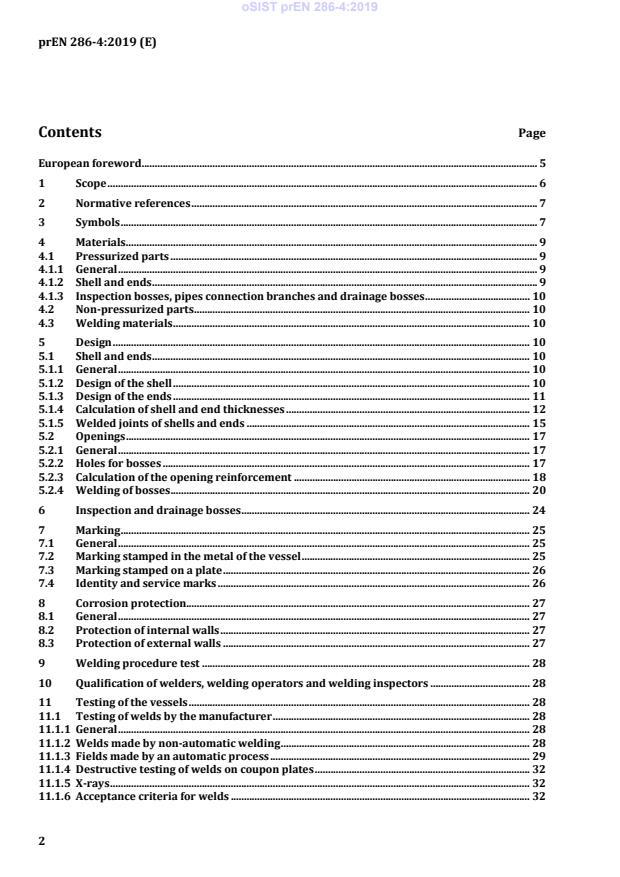
Contents Page
European foreword . 5
1 Scope . 6
2 Normative references . 7
3 Symbols . 7
4 Materials . 9
4.1 Pressurized parts . 9
4.1.1 General . 9
4.1.2 Shell and ends . 9
4.1.3 Inspection bosses, pipes connection branches and drainage bosses . 10
4.2 Non-pressurized parts . 10
4.3 Welding materials . 10
5 Design . 10
5.1 Shell and ends . 10
5.1.1 General . 10
5.1.2 Design of the shell . 10
5.1.3 Design of the ends . 11
5.1.4 Calculation of shell and end thicknesses . 12
5.1.5 Welded joints of shells and ends . 15
5.2 Openings . 17
5.2.1 General . 17
5.2.2 Holes for bosses . 17
5.2.3 Calculation of the opening reinforcement . 18
5.2.4 Welding of bosses . 20
6 Inspection and drainage bosses . 24
7 Marking . 25
7.1 General . 25
7.2 Marking stamped in the metal of the vessel . 25
7.3 Marking stamped on a plate . 26
7.4 Identity and service marks . 26
8 Corrosion protection. 27
8.1 General . 27
8.2 Protection of internal walls . 27
8.3 Protection of external walls . 27
9 Welding procedure test . 28
10 Qualification of welders, welding operators and welding inspectors . 28
11 Testing of the vessels . 28
11.1 Testing of welds by the manufacturer . 28
11.1.1 General . 28
11.1.2 Welds made by non-automatic welding . 28
11.1.3 Fields made by an automatic process . 29
11.1.4 Destructive testing of welds on coupon plates . 32
11.1.5 X-rays . 32
11.1.6 Acceptance criteria for welds . 32
oSIST prEN 286-4:2019
prEN 286-4:2019 (E)
11.1.7 Finish of longitudinal and circular joints . 34
11.2 Dimensional inspection . 35
11.3 Pressure test . 35
12 Delivery . 36
13 Operating instructions . 36
Annex A (normative) Pressure cycling operation . 37
Annex B (informative) Assembly to the vehicles . 38
B.1 General . 38
B.2 Fixing . 38
B.3 Fixing straps . 42
B.3.1 General . 42
B.3.2 Fixing by two straps . 42
B.3.3 Fixing by a single strap . 42
B.4 Insulating tapes . 42
B.5 Mounting . 43
B.5.1 General . 43
B.5.2 Fixing by two straps . 43
B.5.3 Fixing by a single strap . 43
B.6 Pipe connections . 44
B.7 Protection of the drainage mechanism . 44
Annex C (informative) Service surveillance of vessels . 45
C.1 General . 45
C.2 Vessels used at: PS ≤ 6 bar . 45
C.3 Vessels used at: 6 bar < PS ≤ 10 bar . 45
C.4 External inspection . 46
C.4.1 Cleaning . 46
C.4.2 Examination of marking . 46
C.4.3 Inspection of the walls . 46
C.4.3.1 Deformation and irregularities . 46
C.4.3.1.1 General . 46
C.4.3.1.2 Dished ends . 46
C.4.3.1.3 Shell wall . 47
C.4.3.2 Corrosion . 47
C.4.3.3 Other cases leading to rejection of the vessel . 47
C.4.4 Inspection of the fixings . 47
C.5 Internal examination. 47
C.6 Detailed inspection and hydrostatic test . 48
oSIST prEN 286-4:2019
prEN 286-4:2019 (E)
C.6.1 General . 48
C.6.2 Detailed inspection . 48
C.6.2.1 General . 48
C.6.2.2 Preparation . 48
C.6.2.3 Internal and external inspection . 48
C.6.3 Hydrostatic test . 48
C.6.4 Return to service . 48
C.7 Analysis of the results of the annual sampling on 1 % of the population of a specific
type of vessel . 49
C.8 Withdrawal of vehicles or devices to which the vessel is fitted . 49
C.9 Special cases of vessels fitted to a series of vehicles being phased out, vehicles
intended for a museum, or vehicles kept in service for historical reasons . 49
C.10 Rejection . 49
C.11 Filing of results of examination, inspections and tests . 49
C.12 Responsibilities . 49
Annex ZA (informative) Relationship between this European Standard and the essential
requirements of Directive 2014/29/EU aimed to be covered . 50
Bibliography . 51
oSIST prEN 286-4:2019
prEN 286-4:2019 (E)
European foreword
This document (prEN 286-4:2019) has been prepared by Technical Committee CEN/TC 54 “Unfired
pressure vessels”, the secretariat of which is held by BSI.
This document is currently submitted to the CEN Enquiry.
oSIST prEN 286-4:2019
prEN 286-4:2019 (E)
1 Scope
1.1 This document is applicable to simple unfired aluminium alloy pressure vessels, referred to as
“vessel” in this document, designed for air braking equipment and auxiliary pneumatic equipment for
railway rolling stock (see 1.6).
1.2 The vessels to this document are:
a) made from a single shell;
b) made from aluminium alloy;
c) fabricated by welding;
d) used at a maximum working pressure of 10 bar;
e) the product of the maximum working pressure (in bar) and the volume (in litre):
50 bar litres < PV ≤ 10 000 bar litres;
f) made of a cylindrical part of circular cross-section called the shell with two outwardly dished
torispherical ends, that is two dished ends with the same axis of rotation. This document therefore
does not apply to vessels with one or two flat ends or those made up of several compartments;
g) calculated with a design pressure P (See 5.1.4.2);
h) designed for a working temperature of between −50 °C and +100 °C [+65 °C for certain grades of
aluminium alloy (see 4.1.2)];
i) fastened to the vehicles by straps.
1.3 In normal service, a momentary overpressure of 1 bar of the maximum working pressure is
permitted (10 % of PS).
1.4 This document applies to the vessel proper, from the inlet connection to the outlet connection and
to all other connections and fittings belonging to the vessel.
1.5 This document gives the requirements to be met for the calculation, design, fabrication,
inspection during fabrication and certification of the vessel, and fittings for assembly to the vehicle.
These requirements cannot be written in sufficient detail to ensure good workmanship or proper
construction. Each manufacturer is therefore responsible for taking every necessary step to make sure
that the quality of workmanship and construction is such as to ensure compliance with good
engineering practice.
This document gives:
a) in Annex B, recommendations for assembly to the vehicles;
b) in Annex C, recommendations for the service surveillance of vessels.
1.6 The requirements of this document apply to vessels designed to be fitted to rail vehicles used on
the main national networks, urban networks, underground railways, trams, private networks (regional
railways, company railways, etc.).
oSIST prEN 286-4:2019
prEN 286-4:2019 (E)
2 Normative references
The following documents are referred to in the text in such a way that some or all of their content
constitutes requirements of this document. For dated references, only the edition cited applies. For
undated references, the latest edition of the referenced document (including any amendments) applies.
EN ISO 2081, Metallic and other inorganic coatings — Electroplated coatings of zinc with supplementary
treatments on iron or steel (ISO 2081)
EN ISO 6520-1, Welding and allied processes — Classification of geometric imperfections in metallic
materials — Part 1: Fusion welding (ISO 6520-1)
EN ISO 9606-2, Qualification test of welders — Fusion welding — Part 2: Aluminium and aluminium alloys
(ISO 9606-2)
EN ISO 14732, Welding personnel — Qualification testing of welding operators and weld setters for
mechanized and automatic welding of metallic materials (ISO 14732)
EN ISO 15607, Specification and qualification of welding procedures for metallic materials — General
rules (ISO 15607)
EN ISO 15609-1, Specification and qualification of welding procedures for metallic materials — Welding
procedure specification — Part 1: Arc welding (ISO 15609-1)
EN ISO 15614-2, Specification and qualification of welding procedures for metallic materials — Welding
procedure test — Part 2: Arc welding of aluminium and its alloys (ISO 15614-2)
ISO 4520, Chromate conversion coatings on electroplated zinc and cadmium coatings
ISO 6362-2, Wrought aluminium and aluminium alloys — Extruded rods/bars, tubes and profiles —
Part 2: Mechanical properties
3 Symbols
For the purposes of this document, the following symbols apply.
A Elongation at rupture %
A Cross sectional area effective as compensation, of the boss 2
fb mm
A Cross sectional area effective as compensation, of the reinforcing plate 2
fp mm
A Cross sectional area effective as compensation, of the shell 2
fs mm
A Area of the pressurized zone 2
p mm
c Absolute value of the minus rolling tolerance for sheets as quoted in the standard mm
D Outside diameter of the shell of the vessel mm
o
d Internal diameter of the boss mm
ib
d Outside diameter of the boss mm
ob
e Nominal wall thickness mm
e Calculated thickness mm
c
oSIST prEN 286-4:2019
prEN 286-4:2019 (E)
e Calculated thickness of the end mm
ch
e Calculated thickness of the shell mm
cs
e Nominal thickness of the end mm
h
e Wall thickness of the boss contributing to reinforcement mm
rb
e Wall thickness of the reinforcing plate contributing to reinforcement mm
rp
e Wall thickness of the shell contributing to reinforcement mm
rs
f Nominal design stress at the design temperature 2
N/mm
f Permitted stress of the boss 2
b N/mm
g Throat thickness of a weld mm
h External height of the dished part of an end (see Figure 3) mm
h Height of the cylindrical part of the end (see Figure 3) mm
h Internal height of a dished part of the end (see Figure 3) mm
K Design coefficient which is a function of the welding process —
c
L Total length of the vessel mm
L Distance between the axis of a drainage opening and the end of the vessel mm
l Length of the boss contributing to reinforcement mm
rb
lrbi Length of inward projecting boss contributing to reinforcement mm
l Length of the reinforcing plate contributing to reinforcement, measured along the mm
rp
mid surface
l Length of the shell contributing to reinforcement, measured along the mid surface mm
rs
1)
P bar
Design pressure which is a function of the maximum working pressure, the
welding process and inspection used
PS 1) bar
Maximum working pressure
R Internal radius of the spherical part of the end mm
R Local internal radius at the location of the opening in question mm
i
R Minimum tensile strength specified by the manufacturer or by the standard 2
m N/mm
defining the material
Rp0,2 Minimum proof stress 2
N/mm
r Internal radius of the torispherical part of the end mm
Tmin Minimum working temperature °C
Tmax Maximum working temperature °C
V Volume of the vessel litre
1)
All pressures are gauge pressures.
oSIST prEN 286-4:2019
prEN 286-4:2019 (E)
4 Materials
4.1 Pressurized parts
4.1.1 General
The aluminium alloys used in the fabrication of the pressurized parts of the vessels shall fulfil the
following conditions:
a) R ≤ 350 N/mm ;
m
b) elongation after rupture, A, shall be:
— if the test piece is taken parallel to the direction of rolling ≥ 16 %;
— if the test piece is taken perpendicular to the direction of rolling ≥ 14 %.
4.1.2 Shell and ends
The shell and ends shall be made of aluminium alloy sheet or strip of one of the grades given in Table 1.
All materials not listed in Table 1 may be used, provided they meet the requirements of 4.1, are
approved by a notified body, and are manufactured in accordance with a National or International
Standard.
Table 1 — Aluminium alloy materials
c
Temperature
Design temperature
°C
°C
International Maximum
Temper
20 50 100 20 50 65 1 100
ISO
registration temperature
designation
a
designation Minimum proof
Minimum design
a
b
record °C
stress R
stress f
eT
2 2
N/mm N/mm
e
A1Mg2Mn0,8 5049 0 100 80 80 70 48 48 42
e
AlMg3 5754 0 100 80 80 70 48 48 42
e d
A1Mg3Mn 5454 0 100 90 90 90 54 54
54 54
d e d
A1Mg4 5086 0 65 100 100 60 60
90 58 54
e d
AlMg4,5Mn0,7 5083 0 65 125 125 75 75
74 72
d
a
ISO designation and International registration record see ISO 209.
b
Temper designation, see ISO 2107.
c
For intermediate design temperatures linear interpolation may be used.
d
For interpolation purposes only as temperature limit of 65 °C.
e
Interpolated value.
oSIST prEN 286-4:2019
prEN 286-4:2019 (E)
4.1.3 Inspection bosses, pipes connection branches and drainage bosses
The bosses shall be made of 5083, 5086, 5454 or 5754 aluminium alloy bars or tubes in condition M in
accordance with ISO 6362-2.
All materials may be used, provided they meet the requirements of 4.1, are approved by a notified body,
and are manufactured in accordance with a National or International Standard.
4.2 Non-pressurized parts
The accessories to be welded to the vessel, but which do not contribute to its strength, shall be made of
aluminium alloy compatible with the aluminium alloy from which the pressurized parts of the vessel
are made. The product analysis of the aluminium alloy shall meet the following requirements:
— R ≤ 350 N/mm ;
m
— Cu ≤ 0,5 %;
— Zn ≤ 0,25 %.
4.3 Welding materials
The filler material and gas fluxes shall be suitable for the parent metals. The recommended grades of
filler material to be used are 5183 and 5356. These grades are suitable for welding the grades listed in
4.1 and 4.2.
Aluminium-silicon grades shall not be used.
The suitability of the welding products used is verified by means of the welding procedure test (see
Clause 9).
5 Design
5.1 Shell and ends
5.1.1 General
The vessels are of simple geometrical form, composed of a cylindrical body of circular cross-section and
two outwardly dished torispherical ends.
The design of the vessels shall take into account the installation and maintenance conditions. The
installation and maintenance conditions shall be given by the manufacturer or the user.
NOTE Examples of installation and maintenance requirements are given in informative Annexes B and C.
5.1.2 Design of the shell
Shells are generally made from a single sheet. If the shell is made of several welded parts, the number of
circular welds shall be kept to a minimum.
Longitudinal weld seams of parts of the shell shall:
— not be located on the lower part of the vessel defined by an angle of 30° on either side of the
vertical axis (see Figure 1);
— be sufficiently far apart such as to form an angle greater than 40° (see example in Figure 2).
All welds, even of a temporary nature, located outside the designed seams are prohibited.
oSIST prEN 286-4:2019
prEN 286-4:2019 (E)
Key
1 drainage opening
Figure 1— Position of the longitudinal welds on the lower part of the shell
Key
1 drainage point or reference mark on the lower part
Figure 2 — Position of the longitudinal welds in the upper part of the shell
5.1.3 Design of the ends
5.1.3.1 Shape and dimensions of the ends
The torispherical ends shall be made from a single sheet. Dishing and flanging shall be carried out by a
mechanical forming procedure, for example by pressing or spinning. Hand forming is not permitted.
The torispherical ends shall meet the conditions given in Figure 3.
oSIST prEN 286-4:2019
prEN 286-4:2019 (E)
Key
R (nominal) ≥ 0,8 D
o
r (nominal) ≥ 0,1 D
o
h ≥ 3 × e
1min h
a
see Figure 8
Figure 3 — Torispherical end
5.1.3.2 Heat treatment of the ends after forming
The parameters of the heat treatment to which ends are subjected after forming cannot be specified in
this standard as they vary according to the following criteria:
— the grade of aluminium alloy;
— the type of oven (other than direct radiation, convection, etc.);
— the forming process (hot or cold drawing).
The heat treatment shall not affect the values of R and R used in calculating the thickness. In
p0,2 m
addition, after heat treatment the material shall satisfy the following conditions:
— tensile strength R ≤ 350 N/mm ;
m
— elongation after rupture A > 16 %.
The suitability of the heat treatment parameters shall be checked by the approved inspection body
when the manufacturing record is submitted.
5.1.4 Calculation of shell and end thicknesses
5.1.4.1 General
The nominal thickness “e” of the shells and ends shall be such that:
e ≥ e + c
r
The value of “e ” shall in no case be less than 3 mm.
r
oSIST prEN 286-4:2019
prEN 286-4:2019 (E)
The manufacturer shall apply a correction to allow for thinning resulting from the manufacturing
process.
5.1.4.2 Calculation of the shell thickness “e ”
cs
PD
o
eK⋅
cs c
20 fP+
The minimum design stress “f” is taken from Table 1.
NOTE It has been established from the standards quoted in this part that 0,3 R is always greater than
m
0,6 R .
p0,2
For materials not listed in Table 1, the following applies:
For the calculated design stress “f”, one of the two values 0,6 R or 0,3 R from the relevant material
eT m
standard is used, whichever is less.
The values of P and K to be taken into account are:
c
a) Case no. 1: P ≥ 1,15 PS and K = 1 for automatic welding and when tests are carried out in
c
accordance with 11.1.3.1;
b) Case no. 2: P ≥ 1,3 PS and K = 1 for automatic welding and when tests are carried out in accordance
c
with 11.1.3.2;
c) Case no. 3: P ≥ 1,25 PS and K = 1,15 for welding using a non-automatic process and when tests are
c
carried out according to 11.1.2.
5.1.4.3 Calculation of the thickness of the ends “e ”
ch
The end thickness shall be calculated in the following manner:
a) select the values of f from Table 1, and with P = PS, calculate P/(10 f);
b) calculate h /D with h the smaller of the three values:
e o e
D
o
h,
4 Re+
( )
ch
and
D re+
( )
o ch
where
e = e ;
ch cs
2 2
h= eh+ = eR+− R− r− D / 2− e− r
( ) ( )
h2 h o h
(take e = e + 0,3).
h cs
=
oSIST prEN 286-4:2019
prEN 286-4:2019 (E)
0,3 is the minus rolling tolerance for the sheet;
c) determine e /D from Figure 4;
ch o
d) multiply the value found by D to obtain the thickness e ;
o ch
e) verify the calculation with this value in place of that of e ;
cs
Key
a values for h /D
e o
Figure 4 — Theoretical curves for dished ends
EXAMPLE Calculation of the thickness e of an end of aluminium alloy 5083 in accordance with ISO 6361-2
ch
for a vessel of diameter D = 400 mm and a maximum service temperature of 65 °C.
o
oSIST prEN 286-4:2019
prEN 286-4:2019 (E)
P = 1,15 PS = 1,15 × 10 = 11,5 bar (case no. 1 in 5.1.4.2) for the shell
P = PS = 10 bar for the ends
K = 1
c
R = D = 400 mm
o
r = 0,1 D = 40 mm
o
T = 65 °C
max
f = 74 N/mm from (see Table 1)
P/(10 f) = 10/(10 × 74) = 0,013 5
Calculate h /D ), with h = smallest of 3 values:
e o e
a)
D
22
h= e+ R− Rr− −− e− r = 3,38+ 400− 400− 40− − 3,,38− 40 = 79 24
( ) ( ) ( )
h h
D
o
= 99,23
b)
4 Re+
( )
ch
D re+
( )
o ch
c)
= 92, 82
PD
o
when e is taken as equal to e K 3,08
ch cs c
20 fP+
thus e = 3,08 + 0,3 = 3,38
h
giving h = 79,24 and h /D = 0,198
e e o
From Figure 4: e /D = 0,010 1
ch o
e = 0,010 1 × 400 = 4,04
ch
The verification of the calculation with e = 4,04 in place of e = 3,08 gives:
ch cs
e = 4
ch
5.1.5 Welded joints of shells and ends
5.1.5.1 Longitudinal welds
The welds shall be full penetration butt welds.
Backing strips, even of a temporary nature, are not permitted.
5.1.5.2 Circular welds
The shell/end joints permitted are those shown in Figures 5 to 8. The welds in Figures 5 to 7 shall be of
the full penetration type of the shell/end wall; and for Figure 8 full penetration of the shell wall.
For welding of sheets of different nominal thicknesses (shell/end weld), there shall be alignment either
of the neutral axes (Figure 5) or of the walls of the internal face or external face, the connecting slope
not exceeding 25 %; (14°) (see Figures 6 and 7) and the misalignment of a neutral axes not exceeding
==
oSIST prEN 286-4:2019
prEN 286-4:2019 (E)
1 mm. If the misalignment of the neutral axes is greater than 1 mm, levelling shall be carried out as
shown in Figures 7 a) and 7 b).
Figure 5 — Butt weld with centre lines aligned
Figure 6 — Butt weld with centre lines offset
a) b)
Figure 7 — Butt welds with centre lines offset and connecting slope
a) b) c)
Figure 8 — Weld of the shell ring to end with necked edge
oSIST prEN 286-4:2019
prEN 286-4:2019 (E)
5.2 Openings
5.2.1 General
Inspection bosses, pipe connection branches and drainage bosses are cylindrical parts comprising an
internal pipe thread complying with EN ISO 228-1 or an ISO metric thread in accordance with ISO 261.
The permitted shapes and welding are defined in 5.2.4.1 and 5.2.4.2.
The minimum number, dimensions and location on the vessel are defined in Clause 6.
The wall thickness of bosses shall not be less than 2 times the thickness of the sheet to which they are
welded.
5.2.2 Holes for bosses
Where the diameter of the hole in the wall is greater than 75 mm, a reinforcement calculation is
necessary in accordance with the method described in 5.2.3.
Where holes require reinforcement, the distance that they are to be apart is defined in 5.2.3.1.
The maximum distance between the centre of the dished end and the outer edge of any holes shall not
be greater than 0,4 D (see Figure 9).
o
Figure 9 — Position of a hole in an end
Holes in shells and ends should be located as far as possible from welded seams and shall in no case
cross any welded seam.
The distance between any two welds measured from the extremity of the edge preparation shall not be
less than 4 times the nominal thickness of the shell or end, with a minimum of 25 mm (see Figures 10 a)
and 10 b)).
a) b)
Figure 10 — Distance between two welds measured from the end of the edge preparation
oSIST prEN 286-4:2019
prEN 286-4:2019 (E)
5.2.3 Calculation of the opening reinforcement
5.2.3.1 General
The calculation method described in 5.2.3.2 and 5.2.3.3 is applicable to shells and dished ends in which
circular holes are made in compliance with the following conditions and hypotheses.
Reinforcing plates, where used, shall be made from the same material as that of the vessel to which they
are welded.
The distance between openings, measured from the outer face of the reinforcing plates or openings
shall not be less than 2 × l , where 2 openings require reinforcement, or l where only one of the two
rs rs
openings requires reinforcement.
l 2R+ ee
( )
rs i rs rs
(1)
where
a) R = D /2 − e for shells;
i o rs
b) R = R for ends.
i
Reinforcement of the openings is obtained by the use of:
a) recess welded bosses (see Figures 11 a) and 11 b));
b) welded reinforcing plates and recess welded bosses (see Figure 11 c)).
Adequate reinforcement shall be provided in all planes passing through the axis of the opening.
5.2.3.2 Reinforcement of opening
a) Reinforcement of cylindrical shell with boss
Only bosses of the “full penetration” type as shown in Figures 11 a) and 11 b) may be used.
The length of the boss l contributing to the reinforcement, used in Formula (3) for determining A
rb fb
shall not be greater than l [see Formula (2)]:
rs
ll≤
rb rs
(2)
The value of e used for determining A in Formula (3) shall not be more than twice e .
rb fb rs
=
oSIST prEN 286-4:2019
prEN 286-4:2019 (E)
The following condition shall also be complied with:
A
P p
+≤0,5 f
10 AA+
fs fb
(3)
b) Reinforcement of spherical shell with boss
5.2.3.3 Reinforcement by reinforcing plate and boss
c) Reinforcement of spherical shell by reinforcing plate and boss
Figure 11 — Reinforcement of opening
One of the following two conditions shall be complied with:
— if the permissible stress f is less than the stress f:
b
P
A + 0,,5 A + A + 0 7 A ≤ fA + 0,7 A + f ⋅ A
( ( )) ( )
p fs fb fp fs fp b fb
— if the permissible stress f is greater than f:
b
oSIST prEN 286-4:2019
prEN 286-4:2019 (E)
A
P p
+≤0,5 f
10 AA++ 0,7 A
fs fb fp
Where:
a) the areas A , A , A and A are determined as shown in Figures 11 a), 11 b) and 11 c);
p fb fs fp
b) the maximum height of the boss (l ) to be used in the calculation is:
rb
l 08, d− ee
( )
rb 0b rb rb
;
c) the maximum height of the part of the boss (l ) inside the vessel, to be used in the calculation is:
rbi
l = 0,5 l
rbi rb
;
d) the dimensions of the reinforcing plate to be used in the calculation are:
e ≤ e and l ≤ l
rp rs rp rs.
5.2.4 Welding of bosses
5.2.4.1 Inspection openings and pipe connection branches
Welds can be either full penetration welds (see Figures 12 and 13) or partial penetration welds (see
Figure 14).
Figure 12 — Fixing of a boss by an external weld
Figure 13 — Fixing of a boss by internal and external welds
=
oSIST prEN 286-4:2019
prEN 286-4:2019 (E)
3 ≦ g ≦ e
Figure 14 — Fixing of a boss by internal and external fillet welds
5.2.4.2 Drainage openings
The welds shall be full penetration welds of the wall of the vessel. Weld preparation of the vessel wall
may be necessary. Examples of permitted welds are given in Figures 15, 16 and 17.
Figure 15 — Fixing of a drainage boss by an external weld
Figure 16 — Fixing of a drainage boss by internal and external welds
Figure 17 — Fixing of a drainage boss with drainage groove
If the drainage opening cannot be made in the bottom of the vessel, drainage shall nevertheless be
provided by one of the permitted systems shown in Figures 18 to 25.
oSIST prEN 286-4:2019
prEN 286-4:2019 (E)
Figure 18 — Dip tube fixed to an end
Figure 19 — Dip tube fixed to the shell of a horizontal vessel
Figure 20 — Dip tube fixed to the shell of a vertical vessel
Figure 21 — Dip tube fixed to a top end of a vertical vessel
oSIST prEN 286-4:2019
prEN 286-4:2019 (E)
Figure 22 — Dip tube fixed to the upper part of the shell of a horizontal vessel
Key
a see Figures 12, 13 and 14
Figure 23 — Fixing of a dip tube
Key
a see Figures 12, 13 and 14
Figure 24 — Fixing of a dip tube to a boss
Key
a see Figures 12, 13 and 14
Figure 25 — Recessed fixing of a dip tube to a boss
oSIST prEN 286-4:2019
prEN 286-4:2019 (E)
6 Inspection and drainage bosses
The vessels shall have at least the inspection and drainage bosses of the dimensions given in Table 2.
However, for vessels with a PV less than or equal to 1 000 bar litres (with L < 1 500 mm), one boss for
drainage and inspection is sufficient. In this case, the minimum (internal) diameter is 30 mm.
Other bosses intended for pipe connections may be provided, as long as they are located well away from
weld seams as well as away from the knuckle ends.
The locations of the bosses shown in Figure 26 are recommended. Other locations may be specified as
long as they permit access for internal inspection and drainage of the vessel.
Dimensions in millimetres
a) b)
c)
The drainage opening may be located other than in the bottom of the vessel provided that the vessel has
a system for ensuring its complete drainage (see 5.2.4.2).
Figure 26 — Location of openings
Table 2 — Diameters and locations of bosses
All diameters
oSIST prEN 286-4:2019
prEN 286-4:2019 (E)
All diameters
Minimum diameter: 30 mm
d
ib1
A diameter of 30 mm corresponds approximately to internal threads G1 and M33
Minimum diameter: 18 mm
d
ib2
A diameter of 18 mm corresponds approximately to internal threads G1/2 and M20
L L/5 ≤ L ≤ L/3
1 1
7 Marking
7.1 General
Vessels complying with this European standard shall bear the identification and service marks given in
7.4.
These marks are stamped either in the metal of the vessel itself or on a metal plate welded or glued to
the vessel wall. These marks shall be located on the
...