

EN IEC 62828-1:2026
(Main)Reference conditions and procedures for testing industrial and process measurement transmitters - Part 1: General procedures for all types of transmitters
- Status
- Published
- Publication Date
- 03-Aug-2026
- Technical Committee
- CLC/TC 65X - Industrial-process measurement, control and automation
- Current Stage
- 6060 - Document made available - Publishing
- Start Date
- 14-Aug-2026
- Due Date
- 31-Oct-2024
- Completion Date
- 14-Aug-2026


EN IEC 62828-1:2026 is a CLC standard for reference conditions and test procedures for industrial and process measurement transmitters (PMTs). It sets the common testing framework for all PMT types used in industrial process and machinery measurement and control, so manufacturers, test labs, quality teams and buyers can assess performance under the same conditions.
What does EN IEC 62828-1:2026 specify?
EN IEC 62828-1:2026 specifies the general framework for defining reference conditions and test procedures for all industrial and process measurement transmitters. It is the common Part 1 for the IEC 62828 series, and it is used with the parts that cover pressure, temperature, level and flow transmitters.
The scope treats an analogue PMT as a transmitter with only analogue current and/or voltage outputs. All PMTs with only digital outputs, or with both analogue and digital outputs, are treated as digital PMTs. Proximity devices according to the IEC 60947 series with analogue output are excluded.
The document is organized into clauses for scope, normative references, terms and definitions, the general PMT description, reference test conditions, test procedures, and test report and technical documentation. The informative annexes add architecture guidance, test matrices, uncertainty examples, fault-behaviour checks, throughput tests, documentation examples, alarm and range examples, and reference design criteria.
| Annex | What it covers |
|---|---|
| A | General PMT architecture, including sensor, data processing, output, human interface, external interface and power supply assembly |
| B / C | Complete sets of test procedures for standard and operating reference test conditions |
| D | Checks for function blocks, including general qualitative checks and time-dependent and time-independent blocks |
| E | Example of measurement uncertainty determination |
| F | Fault behaviour, fault injection, and human fault tests |
| G | Throughput testing for digital PMT |
| I | Technical documentation, user manual, safety manual, commissioning and maintenance information, calibration certificates |
| J | Signal current range example for a 4 mA to 20 mA PMT, including underrange, overrange and alarm states |
| K | Reference design criteria for IP, IK, electrical safety, hazardous areas and functional safety |
What are the key requirements of EN IEC 62828-1:2026?
EN IEC 62828-1:2026 requires the test program to match the PMT design, its interfaces and the intended operating conditions. In practice, the standard is not just about one accuracy test - it covers how to set up the device, how to classify tests, how to record results and how to document the outcome.
Reference conditions and test planning
Clause 5 defines reference test conditions for environment, power supply, load and mounting position, and it also covers process and atmospheric influences, vibration, shock, drop, topple and EMC. This matters because a transmitter can test well on the bench but drift or fail when temperature, vibration, load or power quality changes.
Clause 5.3.7 points to the IEC 61326 series for EMC immunity and emissions. Clause 5.3.6 sets power-supply classes for voltage and frequency, so the lab must test the transmitter against the supply quality expected in use.
Clause 6.1 classifies tests as type tests, acceptance tests and routine tests, and it also uses the wider idea of evaluation tests. Type tests check the design, routine tests check production and final calibration, and acceptance tests check supplied units against the customer or manufacturer specification.
Clause 6.1.3 states that, unless otherwise agreed, the uncertainty of the test facility and measuring equipment shall be better than or equal to one third of the uncertainty of the instrument under evaluation. That requirement matters because the test setup must be clearly better than the transmitter, otherwise the result is not credible.
Accuracy, behaviour and performance
Clause 6.2 defines the accuracy test approach. The PMT is preconditioned, allowed to stabilize after power-up, and then exercised through full-range traverses in both directions with specified test points. The results are processed as upscale and downscale errors and used to determine inaccuracy, measured error, non-linearity, non-conformity, hysteresis and non-repeatability.
For practical use, this means the report must show more than a pass/fail statement. It must show how the output changed across the range, whether the transmitter behaves differently on rising and falling input, and whether the measured values support the declared accuracy.
Clause 6.2.3 covers static behaviour tests such as insulation resistance, dielectric strength, power consumption, operation region for two-wire analogue PMTs, influence of supply variation, output-load effects, output ripple and overrange. These tests matter when selecting a transmitter for a loop-powered, noisy, high-load or overrange-prone application.
Operating-condition and digital-PMT tests
Clause 6.3 extends testing to operating reference conditions. It includes ambient temperature and humidity effects, vibration, shock, drop and topple, an accelerated operational life test, EMC tests, and further procedures for digital PMTs.
Clause 6.1.4 requires a preliminary assessment using checklists for functionality, configurability, hardware configuration, adjustment and tuning, operability and support. For digital PMTs, the checklists also cover communication compatibility, on-line and off-line configuration, restart conditions, fail-safe conditions, and function blocks.
Reporting and documentation
Clause 7 requires a test report and technical documentation, and it includes total probable error. This is the part that turns test results into usable evidence for quality files, procurement decisions, certification work and maintenance records.
What terms does EN IEC 62828-1:2026 define?
EN IEC 62828-1:2026 defines the test language used across the series, so users can compare results without guessing what a term means.
- Accuracy - the closeness of an indicated value to the true value of the measurand.
- Inaccuracy - the largest positive and negative deviation from the specified characteristic curve under the specified test conditions.
- Repeatability - the closeness of successive measurements under the same conditions, by the same method and instrument, over a short time.
- Hysteresis - the difference between the upscale and downscale outputs at the same input point in one test cycle.
- Non-linearity - the deviation from an ideal straight-line input-output relationship for a linear PMT.
- Non-conformity - the corresponding deviation for a PMT with a non-linear input-output relationship.
- Span - the algebraic difference between the upper and lower limits of the measuring range.
- Step response time - the time from a sudden input change until the output reaches and remains within the specified limits of its final value.
Who uses EN IEC 62828-1:2026?
EN IEC 62828-1:2026 is used by PMT manufacturers, test laboratories, calibration and metrology teams, quality assurance staff, and customers writing specifications or acceptance criteria. It is also used by commissioning, maintenance and integration personnel who need to verify that a transmitter is set up correctly and behaves as expected in service.
The standard is relevant in industrial process and machinery applications, especially where transmitters are connected to measuring and control systems, fieldbus networks or host systems. It is particularly useful when comparing analogue PMTs with digital PMTs, because the test approach covers both the basic signal path and the communication or software functions around it.
Which standards are used with EN IEC 62828-1:2026?
EN IEC 62828-1:2026 relies on several IEC and ISO documents to define terms, operating conditions, EMC, safety and uncertainty handling.
- IEC 60050-300, IEC Vocabularies for measurement terms used in the definitions.
- IEC 60068-2-1, -2-2, -2-6, -2-27, -2-31 and -2-78, environmental tests for cold, dry heat, vibration, shock, rough handling and damp heat.
- IEC 60079, for equipment intended for explosive gas atmospheres.
- IEC 60529 and IEC 62262, for IP and IK enclosure protection.
- IEC 60654-1, -3 and -4, for climatic, mechanical and corrosive operating conditions.
- IEC 61158 and IEC 61918, for fieldbus communication and installation in industrial premises.
- IEC 61326-1, for EMC requirements.
- IEC 61499 and IEC 61804, for function blocks.
- IEC 62381, for FAT, SAT and SIT.
- ISO 10012, ISO/IEC Guide 98-3 and ISO/IEC Guide 99, for measurement management, uncertainty and metrology terminology.
- IEC 62828-2, IEC 62828-3, IEC 62828-4 and IEC 62828-5, which give the specific procedures for pressure, temperature, level and flow transmitters.
What does the EN IEC 62828-1:2026 document contain?
EN IEC 62828-1:2026 contains checklists, matrices, example calculations and structured test procedures that support evaluation, acceptance and documentation. The annexes include examples for PMT architecture, uncertainty processing, fault injection and ranking, throughput under stand-alone and fieldbus conditions, and the technical content expected in datasheets and manuals.
The document also contains example tables and figures for error evaluation, measured error presentation and PMT signal ranges. These are useful when a team needs to build a lab test plan, compare measured performance with a specification, or document calibration and acceptance results in a consistent format.
Annex I lays out the technical documentation a supplier can provide, including model identification, hardware and software revision, measuring ranges, output characteristics, power supply, environmental and mechanical data, approvals and diagnostic functions. Annex K summarizes design-related reference topics such as enclosure protection, electrical safety, hazardous area use and functional safety, which helps when checking whether a transmitter design matches the intended installation.
Relations
- Effective Date
- 18-Jul-2023
- Refers
IEC 61326:2002 - Electrical equipment for measurement, control and laboratory use - EMC requirements - Effective Date
- 21-Jul-2026
- Effective Date
- 21-Jul-2026
- Effective Date
- 21-Jul-2026
- Effective Date
- 21-Jul-2026
- Effective Date
- 21-Jul-2026
- Effective Date
- 21-Jul-2026
- Effective Date
- 21-Jul-2026
- Effective Date
- 21-Jul-2026
- Effective Date
- 21-Jul-2026
- Effective Date
- 21-Jul-2026
- Effective Date
- 21-Jul-2026
- Effective Date
- 14-Jul-2026
- Effective Date
- 14-Jul-2026
- Effective Date
- 14-Jul-2026
Get Certified
Connect with accredited certification bodies for this standard

DVS-ZERT GmbH
German welding certification society.
BSMI (Bureau of Standards, Metrology and Inspection)
Taiwan's standards and inspection authority.
CARES (UK Certification Authority for Reinforcing Steels)
UK certification for reinforcing steels and construction.
Sponsored listings
Frequently Asked Questions
EN IEC 62828-1:2026 is a draft published by CLC. Its full title is "Reference conditions and procedures for testing industrial and process measurement transmitters - Part 1: General procedures for all types of transmitters". This standard covers: Reference conditions and procedures for testing industrial and process measurement transmitters - Part 1: General procedures for all types of transmitters
Reference conditions and procedures for testing industrial and process measurement transmitters - Part 1: General procedures for all types of transmitters
EN IEC 62828-1:2026 is classified under the following ICS (International Classification for Standards) categories: 17.020 - Metrology and measurement in general; 25.040.40 - Industrial process measurement and control. The ICS classification helps identify the subject area and facilitates finding related standards.
EN IEC 62828-1:2026 has the following relationships with other standards: It is inter standard links to EN IEC 62828-1:2018, IEC 61326:2002, EN IEC 60068-2-2:2025, EN 60654-1:1993, EN 61499-4:2006, EN 60654-3:1997, EN IEC 60068-2-78:2025, EN 61010-1:2010, EN 60068-2-27:2009, EN 60068-2-6:2008, EN 61499-2:2005, EN IEC 60068-2-1:2025, EN IEC 61804-4:2020, EN IEC 61804-5:2020, EN IEC 61804-3:2020. Understanding these relationships helps ensure you are using the most current and applicable version of the standard.
EN IEC 62828-1:2026 is available in PDF format for immediate download after purchase. The document can be added to your cart and obtained through the secure checkout process. Digital delivery ensures instant access to the complete standard document.
Standards Content (Sample)
SLOVENSKI STANDARD
oSIST prEN IEC 62828-1:2024
01-maj-2024
Referenčni pogoji in postopki za preskušanje industrijskih in procesnih merilnih
oddajnikov - 1. del: Splošni postopki za vse vrste oddajnikov
Reference conditions and procedures for testing industrial and process measurement
transmitters - Part 1: General procedures for all types of transmitters
Referenzbedingungen und Testmethoden für Industrie- und
Prozessmessgrößenumformer - Teil 1: Allgemeine Testmethoden für alle Arten von
Messumformern
Conditions de référence et procédures pour l'essai des transmetteurs de mesure
industrielle et de processus - Partie 1: Procédures générales pour tous les types de
transmetteurs
Ta slovenski standard je istoveten z: prEN IEC 62828-1:2024
ICS:
25.040.40 Merjenje in krmiljenje Industrial process
industrijskih postopkov measurement and control
oSIST prEN IEC 62828-1:2024 en,fr,de
2003-01.Slovenski inštitut za standardizacijo. Razmnoževanje celote ali delov tega standarda ni dovoljeno.
oSIST prEN IEC 62828-1:2024
oSIST prEN IEC 62828-1:2024
65B/1251/CDV
COMMITTEE DRAFT FOR VOTE (CDV)
PROJECT NUMBER:
IEC 62828-1 ED2
DATE OF CIRCULATION: CLOSING DATE FOR VOTING:
2024-03-08 2024-05-31
SUPERSEDES DOCUMENTS:
65B/1239/RR
IEC SC 65B : MEASUREMENT AND CONTROL DEVICES
SECRETARIAT: SECRETARY:
United States of America Mr Wallie Zoller
OF INTEREST TO THE FOLLOWING COMMITTEES: PROPOSED HORIZONTAL STANDARD:
Other TC/SCs are requested to indicate their interest, if
any, in this CDV to the secretary.
FUNCTIONS CONCERNED:
EMC ENVIRONMENT QUALITY ASSURANCE SAFETY
SUBMITTED FOR CENELEC PARALLEL VOTING NOT SUBMITTED FOR CENELEC PARALLEL VOTING
Attention IEC-CENELEC parallel voting
The attention of IEC National Committees, members of
CENELEC, is drawn to the fact that this Committee Draft for
Vote (CDV) is submitted for parallel voting.
The CENELEC members are invited to vote through the
CENELEC online voting system.
This document is still under study and subject to change. It should not be used for reference purposes.
Recipients of this document are invited to submit, with their comments, notification of any relevant patent rights of which
they are aware and to provide supporting documentation.
Recipients of this document are invited to submit, with their comments, notification of any relevant “In Some Countries”
clauses to be included should this proposal proceed. Recipients are reminded that the CDV stage is the final stage for
submitting ISC clauses. (SEE AC/22/2007 OR NEW GUIDANCE DOC).
TITLE:
Reference conditions and procedures for testing industrial and process measurement transmitters -
Part 1: General procedures for all types of transmitters
PROPOSED STABILITY DATE: 2029
NOTE FROM TC/SC OFFICERS:
electronic file, to make a copy and to print out the content for the sole purpose of preparing National Committee positions.
You may not copy or "mirror" the file or printed version of the document, or any part of it, for any other purpose without
permission in writing from IEC.
oSIST prEN IEC 62828-1:2024
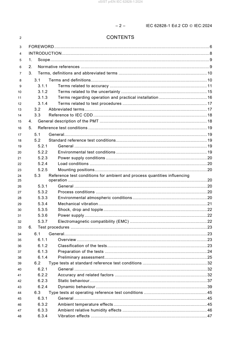
– 2 – IEC 62828-1 Ed.2 CD IEC:2024
2 CONTENTS
3 FOREWORD . 6
4 INTRODUCTION . 8
5 1. Scope . 9
6 2. Normative references . 9
7 3. Terms, definitions and abbreviated terms . 10
8 3.1 Terms and definitions. 10
9 3.1.1 Terms related to accuracy . 11
10 3.1.2 Terms related to the uncertainty . 15
11 3.1.3 Terms regarding operation and practical installation . 16
12 3.1.4 Terms related to test procedures . 17
13 3.2 Abbreviated terms . 17
14 3.3 Reference to IEC CDD . 18
15 4. General description of the PMT . 18
16 5. Reference test conditions . 19
17 5.1 General . 19
18 5.2 Standard reference test conditions . 19
19 5.2.1 General . 19
20 5.2.2 Environmental test conditions . 19
21 5.2.3 Power supply conditions . 20
22 5.2.4 Load conditions . 20
23 5.2.5 Mounting positions . 20
24 5.3 Reference test conditions for ambient and process quantities influencing
25 operation . 20
26 5.3.1 General . 20
27 5.3.2 Process conditions . 20
28 5.3.3 Environmental atmospheric conditions . 20
29 5.3.4 Mechanical vibration . 21
30 5.3.5 Shock, drop and topple . 22
31 5.3.6 Power supply . 22
32 5.3.7 Electromagnetic compatibility (EMC) . 22
33 6. Test procedures . 23
34 6.1 General . 23
35 6.1.1 Overview . 23
36 6.1.2 Classification of the tests . 23
37 6.1.3 Preparation of the tests . 24
38 6.1.4 Preliminary assessment . 25
39 6.2 Type tests at standard reference test conditions . 32
40 6.2.1 General . 32
41 6.2.2 Accuracy and related factors . 32
42 6.2.3 Static behaviour . 37
43 6.2.4 Dynamic behaviour . 39
44 6.3 Type tests at operating reference test conditions . 45
45 6.3.1 General . 45
46 6.3.2 Ambient temperature effects . 45
47 6.3.3 Ambient relative humidity effects . 46
48 6.3.4 Vibration effects . 47
oSIST prEN IEC 62828-1:2024
IEC 62828-1 Ed.2 CD IEC:2024 – 3 –
49 6.3.5 Shock, drop and topple effects . 48
50 6.3.6 Accelerated operational life test . 49
51 6.3.7 EMC tests . 49
52 6.3.8 Further test procedures . 49
53 6.3.9 Additional tests for digital transmitters . 49
54 6.4 Routine tests . 51
55 6.5 Acceptance, integration, periodic and maintenance tests . 51
56 6.5.1 General . 51
57 6.5.2 Periodical verification . 52
58 6.5.3 Periodical calibration . 52
59 7. Test report and technical documentation . 52
60 7.1 Test report . 52
61 7.2 Technical documentation . 52
62 7.3 Total probable error . 52
63 Annex A (Informative) . 54
64 A.1 General description of a PMT . 54
65 A.2 Sensor subsystem . 55
66 A.3 Data processing . 55
67 A.4 Output subsystem . 55
68 A.5 Human interface . 55
69 A.6 External system interface . 56
70 A.7 Power supply assembly. 56
71 Annex B (Informative) . 57
72 B.1 General . 57
73 Annex C (Informative) . 58
74 C.1 General . 58
75 Annex D (Informative) . 59
76 D.1 General . 59
77 D.2 General qualitative checks . 59
78 D.3 Time-dependent function blocks . 59
79 D.4 Time-independent function blocks . 59
80 Annex E (Informative) . Error! Bookmark not defined.
81 E.1 Example of determination of the measurement uncertainty. Error! Bookmark not
82 defined.
83 E.2 Values influencing the uncertainty measurement. Error! Bookmark not defined.
84 E.3 Estimation of standard measurement uncertainty (u) Error! Bookmark not defined.
85 E.4 Combined standard measurement uncertainty (uc) . Error! Bookmark not defined.
86 E.5 Expanded measurement uncertainty (U) . Error! Bookmark not defined.
87 E.6 Metrological confirmation of the instrument . Error! Bookmark not defined.
88 E.7 Analytical uncertainty calculation for more than one measurement cycle . Error!
89 Bookmark not defined.
90 Annex F (Informative) . 60
91 F.1 General . 60
92 Annex G (Informative) . 61
93 G.1 General . 61
94 G.2 Design analysis . 61
95 G.3 Reference conditions . 61
96 G.4 Fault injection test for internal PMT failures . 62
oSIST prEN IEC 62828-1:2024
– 4 – IEC 62828-1 Ed.2 CD IEC:2024
97 G.5 Observations . 63
98 G.5.1 General . 63
99 G.5.2 Reporting and ranking of fault behaviour . 64
100 G.6 Human faults . 66
101 G.6.1 Mis-operation test . 66
102 G.6.2 Maintenance error test . 66
103 G.6.3 Expectations and reporting . 67
104 Annex H (Informative) . 68
105 H.1 General . 68
106 H.2 PMT throughput in stand-alone conditions . 69
107 H.2.1 Reference conditions . 69
108 H.2.2 Test conditions . 69
109 H.2.3 Observations and measurements . 69
110 H.3 Throughput in a fieldbus configuration . 70
111 H.3.1 Reference conditions . 70
112 H.3.2 Test conditions . 70
113 H.3.3 Observations and measurements . 71
114 H.3.4 Precautions . 71
115 Annex I (Informative) . 72
116 I.1 General . 72
117 I.2 Factory acceptance tests FAT (accuracy measurement and others) . 72
118 I.3 Site acceptance tests SAT (visual inspection and calibration test) . 72
119 I.4 Site integration tests SIT (additional test for communications) . 72
120 Annex J (Informative) . 73
121 J.1 General . 73
122 J.2 Technical datasheet . 73
123 J.3 User manual . 76
124 J.4 Safety manual . 76
125 J.5 Commissioning, periodic and maintenance tests . 76
126 J.5.1 General . 76
127 J.5.2 Storage conditions . 76
128 J.5.3 Transportation conditions . 77
129 J.5.4 Mounting position . 77
130 J.5.5 Process connections . 77
131 J.5.6 Mechanical connections . 77
132 J.5.7 Output connections . 77
133 J.6 Calibration certificates . 77
134 Annex K (Informative) . 78
135 K.1 Measuring span . 78
136 K.2 Underrange . 78
137 K.3 Overrange . 78
138 K.4 Low alarm . 78
139 K.5 High alarm . 79
140 Annex L (Informative) . 80
141 L.1 General . 80
142 L.2 Enclosure protection against solid, liquid (IP) and impact (IK) . 80
143 L.2.1 Overview . 80
144 L.2.2 Enclosure protection against solid and liquids (IP code) . 80
oSIST prEN IEC 62828-1:2024
IEC 62828-1 Ed.2 CD IEC:2024 – 5 –
145 L.2.3 Enclosure protection against mechanical impact (IK code) . 80
146 L.2.4 Enclosure protection against corrosive and erosive influences . 80
147 L.3 Electrical safety (insulation resistance, dielectric strength) . 80
148 L.4 Hazardous environment (for application in explosive atmosphere) . 80
149 L.5 Functional safety . 80
150 Bibliography . 81
oSIST prEN IEC 62828-1:2024
– 6 – IEC 62828-1 Ed.2 CD IEC:2024
153 INTERNATIONAL ELECTROTECHNICAL COMMISSION
154 ____________
156 REFERENCE CONDITIONS AND PROCEDURES FOR TESTING INDUSTRIAL
157 AND PROCESS MEASUREMENT TRANSMITTERS
158 Part 1: General procedures for all types of transmitters
162 FOREWORD
163 1) The International Electrotechnical Commission (IEC) is a worldwide organization for standardization comprising
164 all national electrotechnical committees (IEC National Committees). The object of IEC is to promote international
165 co-operation on all questions concerning standardization in the electrical and electronic fields. To this end and
166 in addition to other activities, IEC publishes International Standards, Technical Specifications, Technical Reports,
167 Publicly Available Specifications (PAS) and Guides (hereafter referred to as “IEC Publication(s)”). Their
168 preparation is entrusted to technical committees; any IEC National Committee interested in the subject dealt with
169 may participate in this preparatory work. International, governmental and non-governmental organizations liaising
170 with the IEC also participate in this preparation. IEC collaborates closely with the International Organization for
171 Standardization (ISO) in accordance with conditions determined by agreement between the two organizations.
172 2) The formal decisions or agreements of IEC on technical matters express, as nearly as possible, an international
173 consensus of opinion on the relevant subjects since each technical committee has representation from all
174 interested IEC National Committees.
175 3) IEC Publications have the form of recommendations for international use and are accepted by IEC National
176 Committees in that sense. While all reasonable efforts are made to ensure that the technical content of IEC
177 Publications is accurate, IEC cannot be held responsible for the way in which they are used or for any
178 misinterpretation by any end user.
179 4) In order to promote international uniformity, IEC National Committees undertake to apply IEC Publications
180 transparently to the maximum extent possible in their national and regional publications. Any divergence between
181 any IEC Publication and the corresponding national or regional publication shall be clearly indicated in the latter.
182 5) IEC itself does not provide any attestation of conformity. Independent certification bodies provide conformity
183 assessment services and, in some areas, access to IEC marks of conformity. IEC is not responsible for any
184 services carried out by independent certification bodies.
185 6) All users should ensure that they have the latest edition of this publication.
186 7) No liability shall attach to IEC or its directors, employees, servants or agents including individual experts and
187 members of its technical committees and IEC National Committees for any personal injury, property damage or
188 other damage of any nature whatsoever, whether direct or indirect, or for costs (including legal fees) and
189 expenses arising out of the publication, use of, or reliance upon, this IEC Publication or any other IEC
190 Publications.
191 8) Attention is drawn to the Normative references cited in this publication. Use of the referenced publications is
192 indispensable for the correct application of this publication.
193 9) Attention is drawn to the possibility that some of the elements of this IEC Publication may be the subject of patent
194 rights. IEC shall not be held responsible for identifying any or all such patent rights.
195 International Standard IEC 62828-1 has been prepared by Subcommittee 65B: Measurement
196 and control devices, of IEC Technical Committee 65: Industrial-process measurement, control
197 and automation.
198 The text of this standard is based on the following documents:
FDIS Report on voting
200 Full information on the voting for the approval of this standard can be found in the report on
201 voting indicated in the above table.
202 This publication has been drafted in accordance with the ISO/IEC Directives, Part 2.
203 The committee has decided that the contents of this publication will remain unchanged until the
204 stability date indicated on the IEC web site under "http://webstore.iec.ch" in the data related to
205 the specific publication. At this date, the publication will be
oSIST prEN IEC 62828-1:2024
IEC 62828-1 Ed.2 CD IEC:2024 – 7 –
206 • reconfirmed,
207 • withdrawn,
208 • replaced by a revised edition, or
209 • amended.
211 The National Committees are requested to note that for this publication the stability date
212 is 202X.
213 THIS TEXT IS INCLUDED FOR THE INFORMATION OF THE NATIONAL COMMITTEES AND WILL BE DELETED
214 AT THE PUBLICATION STAGE.
oSIST prEN IEC 62828-1:2024
– 8 – IEC 62828-1 Ed.2 CD IEC:2024
222 INTRODUCTION
223 Most of the current IEC standards on industrial and process measurement transmitters are
224 rather old and were developed having in mind devices based on analogue technologies. Today’s
225 digital industrial and process measurement transmitters are quite different from those analogue
226 transmitters: they include more functions and newer interfaces, both towards the computing
227 section (mostly digital electronic) and towards the measuring section (mostly mechanical). Even
228 if some standards dealing with digital process measurement transmitters already exist, they are
229 not sufficient, since some aspects of the performance are not covered by appropriate test
230 methods.
231 In addition, existing IEC test standards for industrial and process measurement transmitters are
232 spread over many documents, so that for manufacturers and users it is difficult, impractical and
233 time-consuming to identify and select all the standards to be applied to a device measuring a
234 specific process quantity (pressure, temperature, flow, level, etc.).
235 To help manufacturers and users, it was decided to review, complete and reorganize the
236 relevant IEC standards and to create a more suitable, effective and comprehensive standard
237 series that provides in a systematic way all the necessary specifications and tests required for
238 different industrial and process measurement transmitters.
239 To solve the issues mentioned above and to provide an added value for the stakeholders, the
240 new standard series on industrial and process measurement transmitters covers the following
241 main aspects:
242 • Applicable normative references
243 • Specific terms and definitions
244 • Typical configurations and architectures for the various types of industrial and process
245 measurement transmitters
246 • Hardware and software aspects
247 • Interfaces (to the process, to the operator, to the other measurement and control
248 devices)
249 • Physical, mechanical and electrical requirements and relevant tests; clear definition of
250 the test categories: type tests, acceptance tests and routine tests
251 • Performance (its specification, tests and verification)
252 • Environmental protection, hazardous areas application, functional safety, etc.
253 • Structure of the technical documentation.
255 To cover in a systematic way all the topics to be addressed, the standard series is organized in
256 several parts. An updated list of all parts of the IEC 62828-x series, published under the general
257 title “Reference conditions and procedures for testing industrial and process measurement
258 transmitters”, can be found on the IEC website. At the moment of the publication of this
259 standard, the IEC 62828 consists of the following parts:
260 • Part 1: General procedures for all types of transmitters
261 • Part 2: Specific procedures for pressure transmitters
262 • Part 3: Specific procedures for temperature transmitters
263 • Part 4: Specific procedures for level transmitters
264 • Part 5: Specific procedures for flow transmitters
oSIST prEN IEC 62828-1:2024
IEC 62828-1 Ed.2 CD IEC:2024 – 9 –
268 REFERENCE CONDITIONS AND PROCEDURES FOR TESTING INDUSTRIAL
269 AND PROCESS MEASUREMENT TRANSMITTERS
271 Part 1: General procedures for all types of transmitters
275 1. Scope
276 This Part of IEC 62828 establishes a general framework for defining reference conditions and
277 test procedures applicable for assessing the measurement performances of all types of
278 industrial and process measurement transmitters (PMTs) used in measuring and control
279 systems for industrial process and machinery.
280 For the purpose of this document, an analogue PMT is a process measurement transmitter with
281 only analogue current and/or voltage output(s), irrespective the technology adopted and the
282 complexity of the circuitry. All the other process measurement transmitters, with digital output(s)
283 only or with hybrid analogue and digital output(s), are considered to be digital PMTs.
284 This part of IEC 62828 constitutes a common reference for the other parts of the series.
285 Specific test procedures and additional requirements for given types of PMTs (pressure,
286 temperature, level, flow, etc.) are covered by other parts of this series.
287 Proximity devices according IEC 60947-series with analogue output are excluded from the
288 scope of this standard.
289 Note 1: in industrial and process applications, to indicate the process measurement transmitters it is common also
290 to use the terms “industrial transmitters”, or “process transmitters”.
291 Note 2: for better clarity, when the complete definition “industrial and process measurement transmitter” makes the
292 sentence too long in this standard, the short term “transmitter”, or PMT, is used instead.
294 2. Normative references
295 The following referenced documents are indispensable for the application of this document. For
296 dated references, only the edition cited applies. For undated references, the latest edition of
297 the referenced document (including any amendments) applies.
298 IEC 60050-300:2020, International Electrotechnical Vocabulary (IEV)
299 – Electrical and electronic measurements and measuring instruments
300 – Part 311: General terms relating to measurements
301 – Part 312: General terms relating to electrical measurements
302 – Part 313: Types of electrical measuring instruments
303 – Part 314: Specific terms according to the type of instrument
305 IEC 60068-2-1:2007, Environmental testing – Part 2-1: Tests – Test A: Cold
306 IEC 60068-2-2:2007, Environmental testing – Part 2-2: Tests – Test B: Dry heat
307 IEC 60068-2-6:2007, Environmental testing – Part 2-6: Tests – Test Fc: Vibration (sinusoidal)
308 IEC 60068-2-27:2008, Environmental testing – Part 2-27: Tests - Test Ea and guidance: Shock
309 IEC 60068-2-31:2008, Environmental testing – Part 2-31: Tests – Test Ec: Rough handling
310 shocks, primarily for equipment-type specimens
311 IEC 60068-2-78:2012, Environmental testing – Part 2-78:Tests – Test Cab: Damp heat, steady
312 state
oSIST prEN IEC 62828-1:2024
– 10 – IEC 62828-1 Ed.2 CD IEC:2024
314 IEC 60079 (all parts), Electrical apparatus for explosive gas atmospheres
315 IEC 60529:1989 + Amd1:1999 + Amd2:2013, Degrees of protection provided by enclosures (IP
316 code)
317 IEC 60654-1:1993, Industrial-process measurement and control equipment - Operating
318 conditions - Part 1: Climatic conditions
319 IEC 60654-3:1983, Operating conditions for industrial-process measurement and control
320 equipment - Part 3: Mechanical influences
321 IEC 60654-4:1987, Operating conditions for industrial-process measurement and control
322 equipment. Part 4: Corrosive and erosive influences.
323 IEC 61158 (all parts), Industrial communication networks – Fieldbus specifications
324 IEC 61326-1:2020, Electrical equipment for measurement, control and laboratory use - EMC
325 requirements - Part 1: General requirements
326 IEC 61499 series, Function blocks
327 IEC 61804 (all parts), Function blocks (FB) for process control
328 IEC 61918:2018 Industrial communication networks - Installation of communication networks in
329 industrial premises
330 IEC 61987-1:2006, Industrial-process measurement and control - Data structures and elements
331 in process equipment catalogues - Part 1: Measuring equipment with analogue and digital
332 output
333 IEC 61987-11:2016, Industrial-process measurement and control - Data structures and
334 elements in process equipment catalogues - Part 11: List of Properties (LOP) of measuring
335 equipment for electronic data exchange - Generic structures
336 IEC 61987-13:2016, Industrial-process measurement and control - Data structures and
337 elements in process equipment catalogues - Part 13: Lists of properties (LOP) for pressure
338 measuring equipment for electronic data exchange
339 IEC 62262:2002, Degrees of protection provided by enclosures for electrical equipment against
340 external mechanical impacts (IK Code)
341 IEC 62381:2012, Automation systems in the process industry - Factory acceptance test (FAT),
342 site acceptance test (SAT) and site integration test (SIT)
343 ISO 10012:2004, Measurement management systems - Requirements for measurement
344 processes and measuring equipment
345 ISO/IEC Guide 98-3:2008, Uncertainty of measurement - Part 3: Guide to the expression of
346 uncertainty in measurement (GUM:1995)
347 ISO/IEC Guide 99:2007, International Vocabulary of Metrology - Basic and general concepts
348 and associated terms (VIM:2007)
349 3. Terms, definitions and abbreviated terms
350 3.1 Terms and definitions
351 For the purposes of this document, the following terms and definitions apply.
352 ISO and IEC maintain terminological databases for use in standardization at the following
353 address:
354 • IEC Electropedia; available at http//www.electropedia.org
355 • ISO Online browsing platform: available at http//www.iso.org/obp
oSIST prEN IEC 62828-1:2024
IEC 62828-1 Ed.2 CD IEC:2024 – 11 –
356 The terms are divided in four groups for consistency.
357 3.1.1 Terms related to accuracy
358 3.1.1.1
359 accuracy (of a measuring instrument)
360 quality which characterizes the ability of a measuring instrument to provide an indicated value
361 close to a true value of the measurand
362 Note 1 to entry: This term is used in the "true value" approach.
363 Note 2 to entry: Accuracy is all the better when the indicated value is closer to the corresponding true value.
364 [SOURCE: IEC 60050-311:2001, 311-06-08]
365 3.1.1.2
366 communication interface
367 Interface for input or output of variable parameters (e.g. correction of the characteristic curve)
368 and data (e.g. measurement and calibration data, electronic nameplate, device status) of the
369 pressure transmitter.
370 3.1.1.3
371 conformity
372 ability of a measuring instrument to provide an indication having a specified characteristic curve
373 which can be linear, logarithmic, parabolic, etc.
374 3.1.1.4
375 dead band (dead zone)
376 finite range of values within which a variation of the input variable does not produce any
377 measurable change in the output variable
378 Note 1 to entry: When this type of characteristic is intentional, it is sometimes called neutral zone
379 Note 2 to entry: This entry was numbered 351-24-14 in IEC 60050-351:2006.
380 Note 3 to entry: This value is usually insignificant for the actual instruments.
381 [SOURCE: IEC 60050-351:2013, 351-45-15, modified (Note 3 added)]
382 3.1.1.5
383 error
384 discrepancy between a computed, observed or measured value or condition, and the true,
385 specified or theoretically correct value or condition
386 Note to entry: An error within a system may be caused by failure of one or more of its components, or by activation
387 of a systematic fault.
388 [SOURCE: IEC 60050-192:2015, 192-03-02]
389 3.1.1.6
390 hysteresis
391 phenomenon represented by a characteristic curve which has a branch, called ascending
392 branch, for increasing values of the input variable, and a different branch, called descending
393 branch, for decreasing values of the input variable
394 Note to entry: the CDD code of this entry for Electronic Data Exchange is ABB661 and the hysteresis is defined as
395 the difference between consecutive upscale and downscale outputs for any single test cycle at the same input test
396 point
397 [SOURCE: IEC 60050-351:2013, 351-45-16, modified (Note to entry added)]
398 3.1.1.7
399 inaccuracy
400 maximum positive and negative deviation from the specified characteristic curve observed in
401 testing a device under specified conditions and by a specified procedure
402 Note to entry: Accuracy is defined in IEC 60050-300, definition 311-06-08.
oSIST prEN IEC 62828-1:2024
– 12 – IEC 62828-1 Ed.2 CD IEC:2024
403 3.1.1.8
404 linearity
405 ability of a measuring instrument to provide an indication having a linear relationship with a
406 defined quantity other than an influence quantity
407 Note to entry: The method of expression of lack of linearity is different for different kinds of instrument and is
408 established in each particular instance.
409 [SOURCE: IEC 60050-311:2001, 311-06-05]
410 3.1.1.9
411 long term drift
412 drift in output monitored for 30 days at 90 % of span
413 [SOURCE: IEC 61987-1:2008, 3.22]
414 3.1.1.10
415 long term stability
416 drift of zero output signal in percent of full scale limit after a given period of normal operating conditions
417 Note 1 to entry: the long term stability can be evaluated over a different period of time, e.g. 6 months, 1, 2 or 5 years.
418 Sometime manufacturers declare a life-time stability.
419 Note 2 to entry: depending the type of PMT, the drift can be referred to an upper range limit (e.g. digital pressure
420 PMTs), a fixed value (e.g. certain level PMTs), a full scale (e.g. some analogue PMTs), etc.
421 Note 3 to entry: the CDD code of this entry for Electronic Data Exchange is ABB551, modified (time period)
422 3.1.1.11
423 measured error
424 largest positive or negative value of errors of the average upscale or downscale values at each
425 point of measurement
426 3.1.1.12
427 measuring range
428 range defined by two values of the measurand, or quantity to be supplied, within which the limits of
429 uncertainty of the measuring instrument are specified
430 Note to entry: An instrument can have several measuring ranges
431 [SOURCE: IEC 60050-311:2001, 311-03-12]
432 3.1.1.13
433 non-conformity
434 deviation from ideal behavior for devices that have a non-linear input/output relationship (which can be
435 linear, logarithmic, parabolic, etc.), determined from the curve plotted using the overall average of
436 corresponding upscale and downscale errors
437 Note 1 to entry: Non-conformity can be calculated and expressed in one of three ways:
438 – independent: curve positioned so as to minimize the maximum deviation;
439 – terminal-based: curve positioned so as to coincide with the actual characteristic curve at the upper and lower
440 range-values;
441 – zero-based: curve positioned so as to coincide with the actual characteristic curve at the lower range-value.
442 Note 2 to entry: The corresponding properties are to be found in the CDD.
443 [SOURCE: IEC 61987-13:2016, modified]
444 3.1.1.14
445 non-linearity
446 deviation from ideal behavior for devices that have a linear input/out relationship, determined
447 from the curve plotted using the overall average of corresponding upscale and downscale errors
448 Note 1 to entry: Non-linearity can be calculated and expressed in one of three ways:
449 – independent: line positioned so as to minimize the maximum deviation;
450 – terminal-based: line positioned so as to coincide with the actual characteristic curve at the upper and lower range-
451 values;
452 – zero-based: line positioned so as to coincide with the actual characteristic curve at the lower range-value.
453 Note 2 to entry: The corresponding properties are to be found in the CDD.
oSIST prEN IEC 62828-1:2024
IEC 62828-1 Ed.2 CD IEC:2024 – 13 –
454 [SOURCE: IEC 61987-13:2016]
455 3.1.1.15
456 overrange
457 An input signal larger than an instrument is designed to accept or measure
458 Note 1 to entry: That part of the proportional range where the analogue output signal represents a process value
459 above the configured measuring range.
460 NOTE 2 to entry: The output signal can be not calibrated in overrange state.
462 3.1.1.16
463 overshoot
464 for a step response, the maximum transient deviation from the final steady-state value of the
465 output variable, expressed as a percentage of the difference between the final and the initial
466 steady-state values
467 Note to entry: the CDD code of this entry for Electronic Data Exchange is ABD684
468 [SOURCE: IEC 60050-351:2013, 351-45-38 modified]
469 3.1.1.17
470 repeatability
471 closeness of agreement between the results of successive measurements of the same
472 measurand, carried out under the same conditions of measurement, i.e.:
473 • by the same measurement procedure,
474 • by the same observer,
475 • with the same measuring instruments, used under the same conditions,
476 • in the same laboratory,
477 • at relatively short intervals of time.
478 Note to entry: The concept of "measurement procedure" is defined in VIM 2.5
479 [SOURCE: IEC 60050-311:2001, 311-06-06]
480 3.1.1.18
481 settling time
482 for a step response the duration of the time interval between the instant of the step change of
483 an input variable and the instant, when the difference between the step response and their
484 steady-state value remains smaller than the transient value tolerance
485 [SOURCE: IEC 60050-351:2013, 351-45-37, modified (Figure and Note missing)]
486 3.1.1.19
487 signal
488 physical variable quantity, one or more parameters of which carry information about one or
489 more variable quantities
490 Note 1 to entry: These parameters are designed “information parameters”.
491 Note 2 to entry: This entry was numbered 351-21-51 in IEC 60050-351:2006.
492 [SOURCE: IEC 60050-351:2013, 351-41-17]
493 3.1.1.20
494 span
495 algebraic difference between the values of the upper and lower limits of the measuring range
496 Note 1 to entry: limit has not to be intend as physical limits regarding the capabilities of the device, rather the upper
497 and lower values defined for the relevant application,
498 Note 2 to entry: the CDD code
...